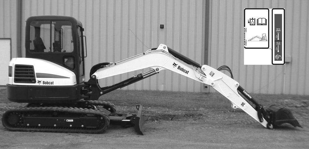
17 minute read
ELECTRICAL SYSTEM


Description
Figure 319
Fuse And Relay Location / Identification
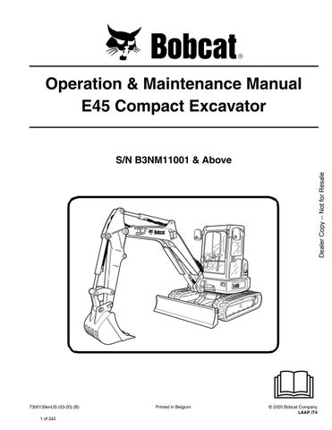
A decal is inside the fuse cover to show location and amp ratings.
Remove the cover to check or replace the fuses and relays.
The location and sizes are shown in [Figure 320].
Always replace fuses using the same type and capacity.
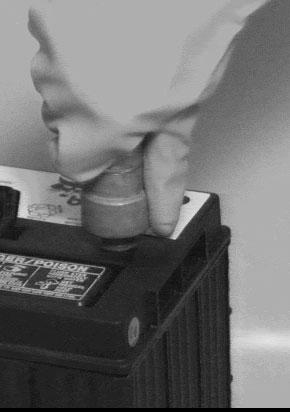
The excavator has a 12 volt, negative ground electrical system. The electrical system is protected by fuses (Item 1) [Figure 319] located under the right side cover of the excavator. The fuses will protect the electrical system when there is an electrical overload. The reason for the overload must be found and corrected before starting the engine again.
The battery cables must be clean and tight. Check the electrolyte level in the battery. Add distilled water as needed. Remove acid or corrosion from the battery and cables with a sodium bicarbonate and water solution.
Put Battery Saver P/N 6664458 or grease on the battery terminals and cable ends to prevent corrosion.
Warning
AVOID INJURY OR DEATH
Batteries contain acid which burns eyes and skin on contact. Wear goggles, protective clothing and rubber gloves to keep acid off body.
In case of acid contact, wash immediately with water. In case of eye contact get prompt medical attention and wash eye with clean, cool water for at least 15 minutes.
If electrolyte is taken internally drink large quantities of water or milk! DO NOT induce vomiting. Get prompt medical attention.
W-2065-0807
ELECTRICAL SYSTEM (CONT’D)

Fuse And Relay Location / Identification (Cont’d)
Figure 320
ELECTRICAL SYSTEM (CONT’D)
Battery Maintenance
Open the right side cover. (See RIGHT SIDE COVER on Page 160.).
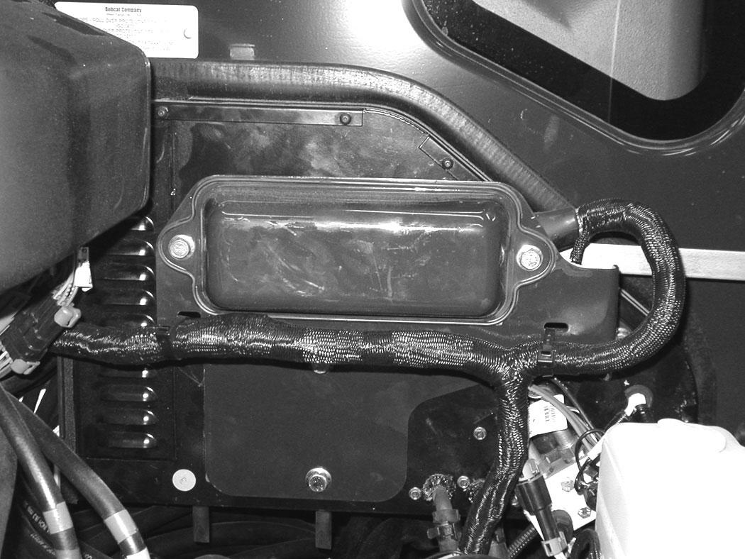
The battery cables must be clean and tight [Figure 322]. Remove acid or corrosion from the battery and cables using a sodium bicarbonate and water solution. Cover the battery terminals and cable ends with battery saver grease to prevent corrosion.
Check for broken or loose connections.
If the battery cables are removed for any reason, disconnect the negative (-) cable first. When installing the battery cables, make the last connection the negative (-) cable to the battery.
The original equipment battery is maintenance free. If a replacement battery is installed, check the electrolyte level in the battery.
If the electrolyte level is lower than 13 mm (0.50 in) above the plates, add distilled water only.
Warning
Avoid Injury Or Death
Batteries contain acid which burns eyes and skin on contact. Wear goggles, protective clothing and rubber gloves to keep acid off body.
In case of acid contact, wash immediately with water. In case of eye contact get prompt medical attention and wash eye with clean, cool water for at least 15 minutes.
If electrolyte is taken internally drink large quantities of water or milk! DO NOT induce vomiting. Get prompt medical attention.
W-2065-0807
ELECTRICAL SYSTEM (CONT’D)
Using A Booster Battery (Jump Starting)
Important
If jump starting the excavator from a second machine:
When jump starting the excavator from a battery installed in a second machine, make sure the engine is NOT running while using the glow plugs. High voltage spikes from a running machine can burn out the glow plugs.
I-2060-0906
If it is necessary to use a booster battery to start the engine, BE CAREFUL! There must be one person in the operator’s seat and one person to connect and disconnect the battery cables.
Be sure the key switch is OFF. The booster battery must be 12 volt.
Open the tailgate. (See TAILGATE on Page 159.)
Start the engine. After the engine has started, remove the ground (-) cable first (Item 2) [Figure 323].
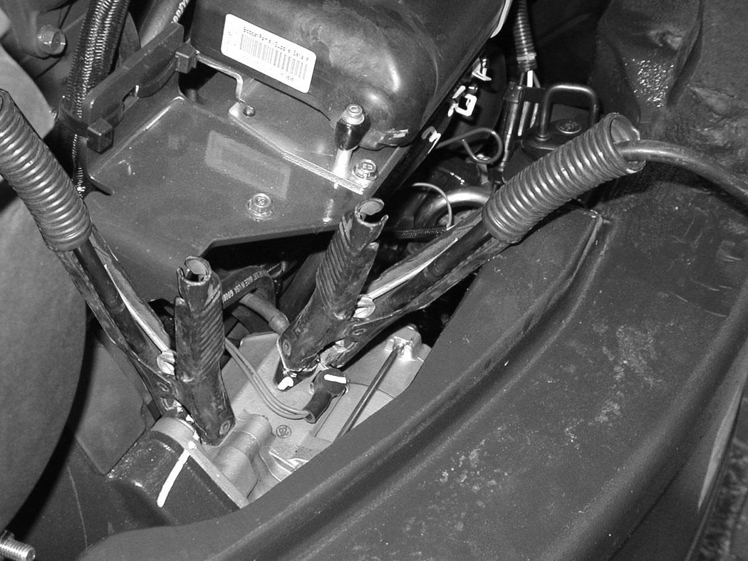
Disconnect the cable from the excavator starter (Item 1) [Figure 323]
NOTE: (See Cold Temperature Starting on Page 74.)
Important
Damage to the alternator can occur if:
•Engine is operated with battery cables disconnected.
•Battery cables are connected when using a fast charger or when welding on the excavator. (Remove both cables from the battery.)
•Extra battery cables (booster cables) are connected wrong.
I-2223-0903
Warning
AVOID INJURY OR DEATH
Batteries contain acid which burns eyes and skin on contact. Wear goggles, protective clothing and rubber gloves to keep acid off body.
In case of acid contact, wash immediately with water. In case of eye contact get prompt medical attention and wash eye with clean, cool water for at least 15 minutes.
P-97133A
Connect one end of the first cable to the positive (+) terminal of the booster battery. Connect the other end of the same cable to the positive (+) terminal (Item 1) [Figure 323] of the excavator starter.
Connect one end of the second cable to the negative (-) terminal of the booster battery. Connect the other end of the same cable to the starter mounting bolt (Item 2) [Figure 323]
If electrolyte is taken internally drink large quantities of water or milk! DO NOT induce vomiting. Get prompt medical attention.
W-2065-0807
ELECTRICAL SYSTEM (CONT’D)
Removing And Installing The Battery
Open the right side cover. (See RIGHT SIDE COVER on Page 160.)
Disconnect the negative (-) cable (Item 1) [Figure 324] first.
Disconnect the positive (+) cable (Item 2) [Figure 324].
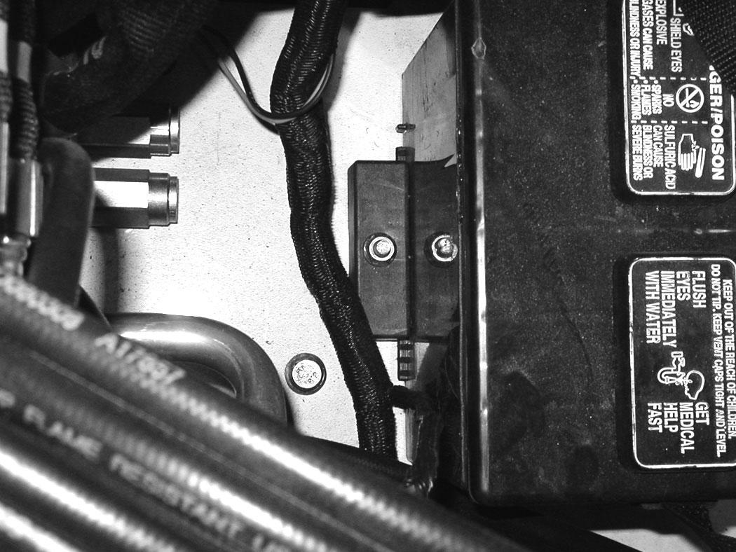
Remove the bolt (Item 1) [Figure 325] and remove the hold-down clamp.
Remove the battery.
Always clean the terminals and the cable ends, even when installing a new battery.
Install the battery. Install the hold-down clamp and tighten the bolts.
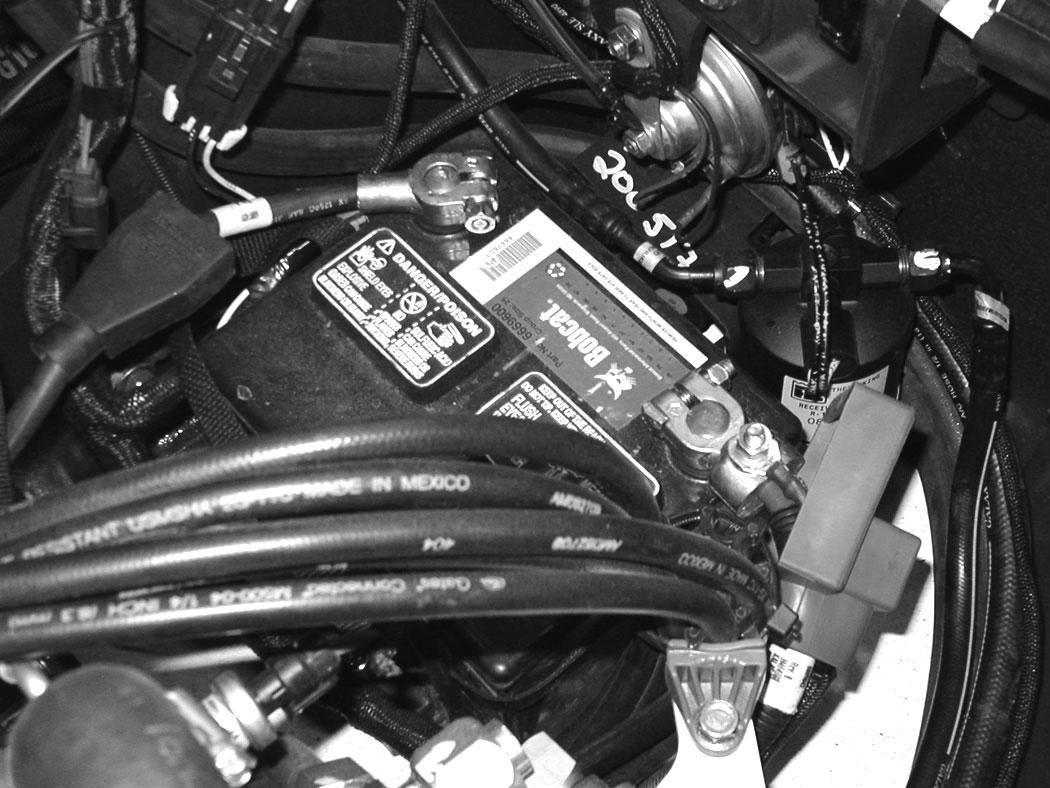
Connect the battery cables. Connect the negative (-) cable (Item 1) [Figure 324] last to prevent sparks.
Warning
AVOID INJURY OR DEATH
Batteries contain acid which burns eyes and skin on contact. Wear goggles, protective clothing and rubber gloves to keep acid off body.
In case of acid contact, wash immediately with water. In case of eye contact get prompt medical attention and wash eye with clean, cool water for at least 15 minutes.
If electrolyte is taken internally drink large quantities of water or milk! DO NOT induce vomiting. Get prompt medical attention.
W-2065-0807
Hydraulic System
Checking And Adding Hydraulic Oil
Put the machine on a flat level surface.
Retract the arm and bucket cylinders, extend the boom cylinder, put the bucket on the ground and lower the blade. Stop the engine.
Open the right side cover. (See RIGHT SIDE COVER on Page 160.)
Figure 326
Park the machine in the position shown [Figure 326]. (The preferred method is to check the hydraulic oil when it is cold.)
Check the hydraulic oil level, it must be visible in the sight gauge (Item 1) [Figure 326]. The decal on the hydraulic tank shows the correct fill level.
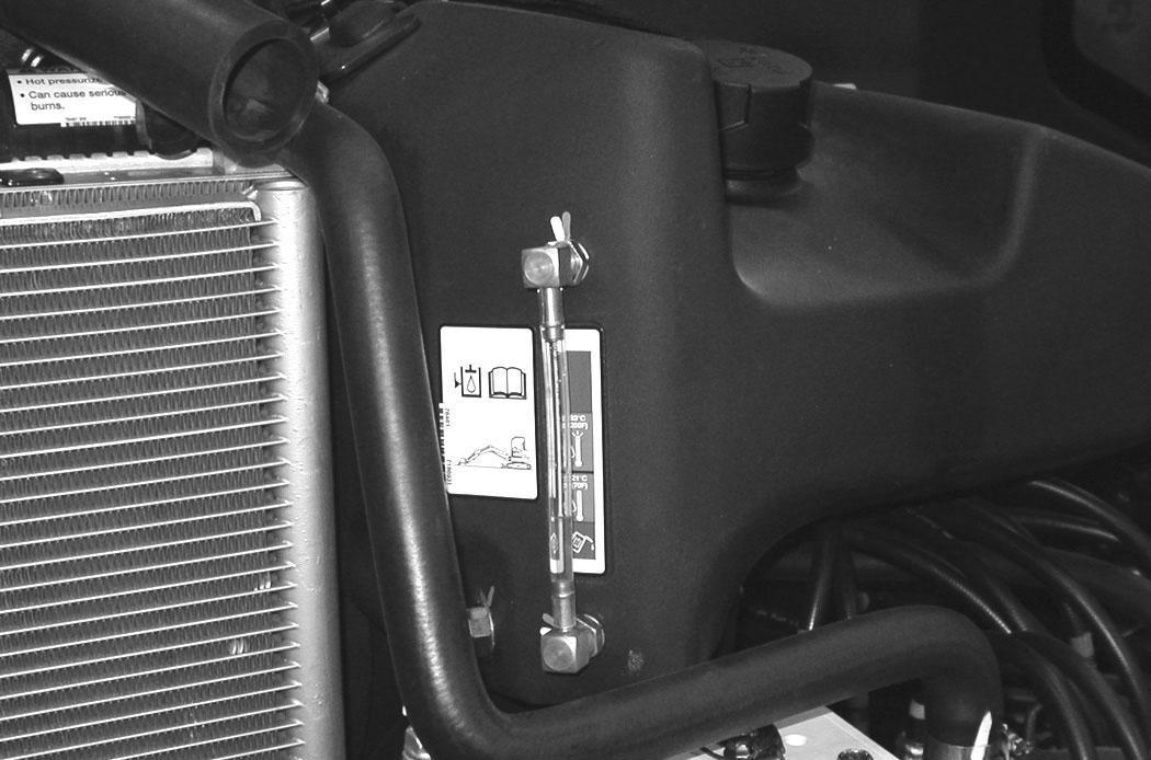
A - Correct Oil Level COLD (Preferred)
B - Correct Oil Level HOT (Optional)
Clean the surface around the reservoir cap and remove the cap from the reservoir (Item 2) [Figure 326].
Warning
AVOID INJURY OR DEATH
Always clean up spilled fuel or oil. Keep heat, flames, sparks or lighted tobacco away from fuel and oil. Failure to use care around combustibles can cause explosion or fire.
W-2103-0508
Figure 327
Check the condition of the fill strainer screen (Item 1) [Figure 327]. Clean or replace as necessary.
Be sure the screen is installed before adding fluid. Add the correct fluid (See [Figure 328]) to the reservoir until it is visible in the sight gauge. (See Capacities on Page 232.)
Check the cap and clean as necessary. Replace the cap if damaged. Install the cap.
Close the right side cover and tailgate.
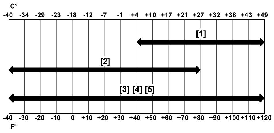
Hydraulic / Hydrostatic Fluid Chart
Figure 328
HYDRAULIC / HYDROSTATIC FLUID RECOMMENDED ISO VISCOSITY GRADE (VG) AND VISCOSITY INDEX (VI)
TEMPERATURE RANGE ANTICIPATED DURING MACHINE USE
[1] VG 100; Minimum VI 130
[2] VG 46; Minimum VI 150
[3] BOBCAT All-Season Fluid
[4] BOBCAT Synthetic Fluid
[5] BOBCAT Biodegradable Hydraulic / Hydrostatic Fluid (Unlike biodegradable fluids that are vegetable based, Bobcat biodegradable fluid is formulated to prevent oxidation and thermal breakdown at operating temperatures.)
Use only recommended fluid in the hydraulic system [Figure 328].
HYDRAULIC SYSTEM (CONT’D)
Removing And Replacing The Hydraulic Filters
Hydraulic Filter
Warning
AVOID INJURY OR DEATH
Always clean up spilled fuel or oil. Keep heat, flames, sparks or lighted tobacco away from fuel and oil. Failure to use care around combustibles can cause explosion or fire.
See the SERVICE SCHEDULE for the correct service interval. (See SERVICE SCHEDULE on Page 153.)
Remove the hydraulic filter (Item 1) [Figure 330]
Clean the housing where the filter gasket makes contact. Put clean hydraulic fluid on the gasket. Install the new filter and hand tighten only. Use a genuine Bobcat replacement filter.
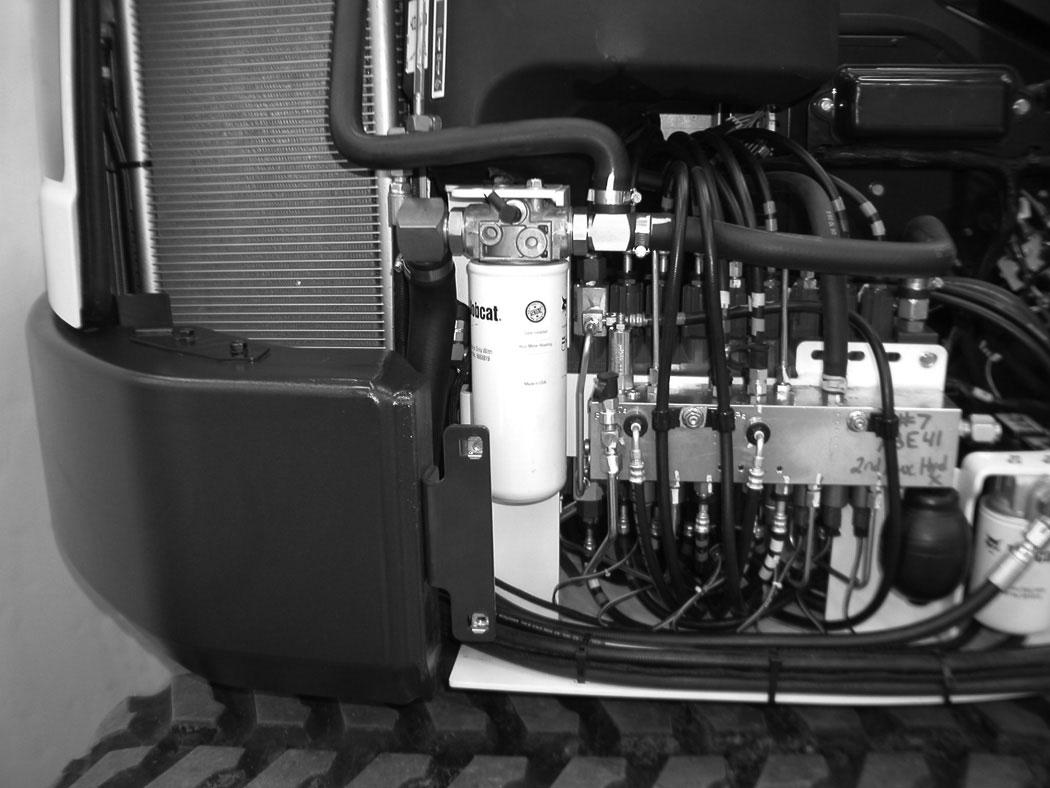
Open the right side cover. (See RIGHT SIDE COVER on Page 160.)
For easier access to change the hydraulic filter, remove the lower right side panel.
Remove the four bolts (Item 1) from the side panel (Item 2) [Figure 329]. Remove the side panel.
HYDRAULIC SYSTEM (CONT’D)
Removing And Replacing The Hydraulic Filters (Cont’d)
Case Drain Filter
Warning
AVOID INJURY OR DEATH
Always clean up spilled fuel or oil. Keep heat, flames, sparks or lighted tobacco away from fuel and oil. Failure to use care around combustibles can cause explosion or fire.
W-2103-0508
See the SERVICE SCHEDULE for the correct service interval. (See SERVICE SCHEDULE on Page 153.)
The case drain filter is located in the right front corner of the excavator.
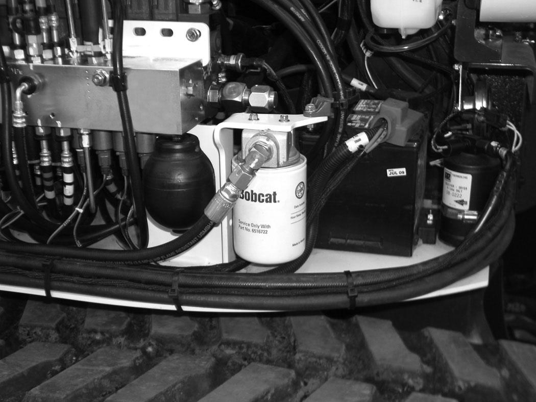
Open the right side cover. (See RIGHT SIDE COVER on Page 160.)
For easier access to change the case drain filter, remove the lower right side panel.
Remove the four bolts (Item 1) from the side panel (Item 2) [Figure 329]. Remove the side panel.
P-97141
HYDRAULIC SYSTEM (CONT’D)
Removing And Replacing The Hydraulic Fluid
See the SERVICE SCHEDULE for the correct service interval. (See SERVICE SCHEDULE on Page 153.)
Warning
Avoid Injury Or Death
Diesel fuel or hydraulic fluid under pressure can penetrate skin or eyes, causing serious injury or death. Fluid leaks under pressure may not be visible. Use a piece of cardboard or wood to find leaks. Do not use your bare hand. Wear safety goggles. If fluid enters skin or eyes, get immediate medical attention from a physician familiar with this injury.
W-2072-0807
Retract the arm and bucket cylinders, lower the bucket to the ground. Stop the engine.
Open the tailgate. (See TAILGATE on Page 159.)
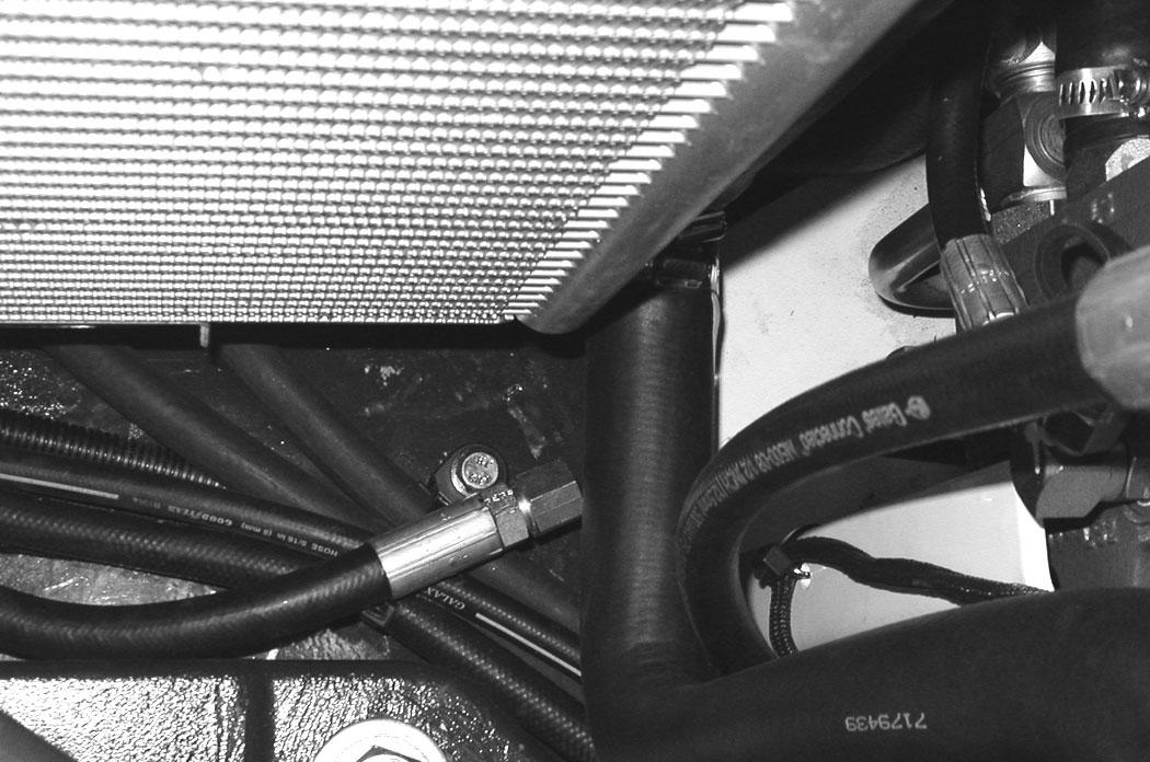
Reposition the drain hose out the bottom of the upperstructure and remove the cap (Item 1) [Figure 333]
Drain the fluid into a container.
Recycle or dispose of the fluid in an environmentally safe manner.
Install the cap (Item 1) [Figure 333] and position the drain hose back to the storage position (Item 1) [Figure 332]
Add fluid to the reservoir. (See HYDRAULIC SYSTEM on Page 179.)
The
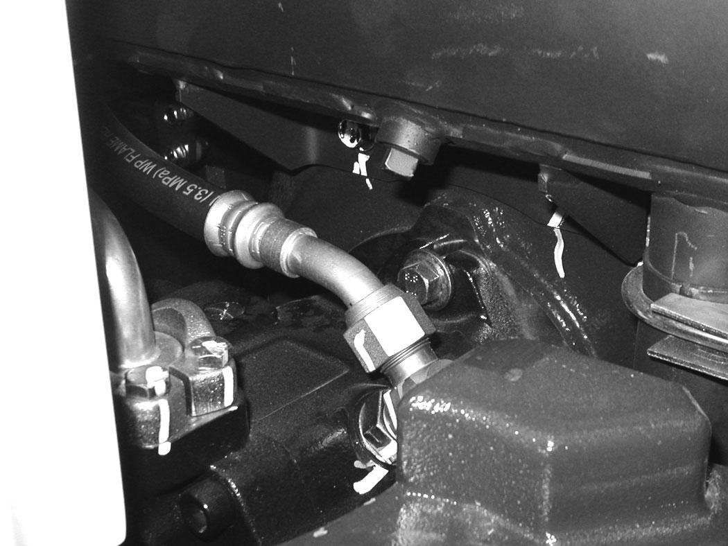
With the engine OFF, loosen the hose (Item 1) [Figure 334] on the hydraulic pump until all air is purge from the system. Tighten the hose after a steady stream of hydraulic fluid, free of any air bubbles, drains from the hose. DO NOT RUN THE MACHINE WITH THE HOSE LOOSE.
Start the engine and operate the machine through the hydraulic functions. Stop the engine. Check the fluid level and add as needed.
SPARK ARRESTER MUFFLER Cleaning Procedure
See the SERVICE SCHEDULE for the correct service interval. (See SERVICE SCHEDULE on Page 153.)
Warning
Avoid Injury Or Death
When an engine is running in an enclosed area, fresh air must be added to avoid concentration of exhaust fumes. If the engine is stationary, vent the exhaust outside. Exhaust fumes contain odorless, invisible gases which can kill without warning.
W-2050-0807
Warning
Stop engine and allow the muffler to cool before cleaning the spark chamber. Wear safety goggles. Failure to obey can cause serious injury.
W-2011-1285
Warning
Never use machine in atmosphere with explosive dust or gases or where exhaust can contact flammable material. Failure to obey warnings can cause injury or death.
W-2068-1285
Warning
When the engine is running during service, the steering levers must be in neutral.
Failure to do so can cause injury or death.
W-2203-0595
Do not operate the excavator with a defective exhaust system.
Stop the engine. Open the tailgate. (See TAILGATE on Page 159.)
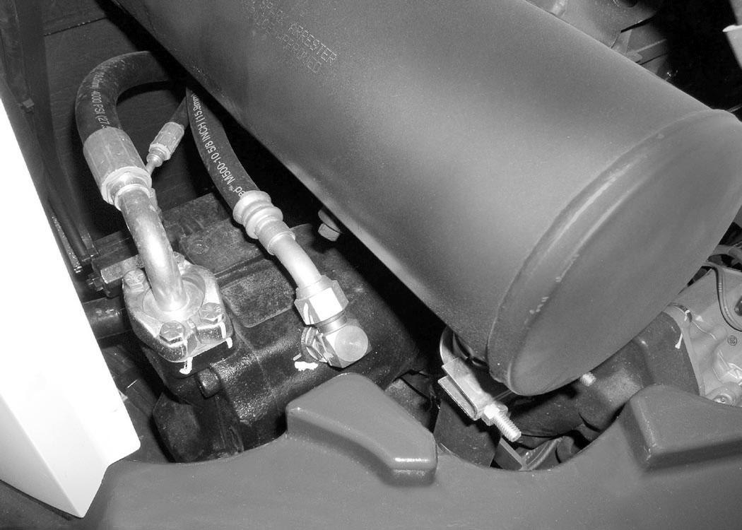
Remove the plug (Item 1) [Figure 335] from the bottom of the muffler.
Start the engine and run for about 10 seconds while a second person, wearing safety glasses, holds a piece of wood over the outlet of the muffler. The carbon deposits will be forced out of the muffler plug hole (Item 1) [Figure 335]
Stop the engine. Install and tighten the plug.
Close the tailgate.
Important
This machine is factory equipped with a U.S.D.A. Forestry Service approved spark arrester exhaust system.
The spark arrester muffler, if equipped, must be cleaned to keep it in working condition. The spark arrester muffler must be serviced by dumping the spark chamber every 100 hours of operation.
On some models, the turbocharger functions as the spark arrester and must operate correctly for proper spark arrester function.
If this machine is operated on flammable forest, brush, or grass covered land, it must be equipped with a spark arrester attached to the exhaust system and maintained in working order. Failure to do so will be in violation of California State Law, Section 4442. PRC. Refer to local laws and regulations for spark arrester requirements.
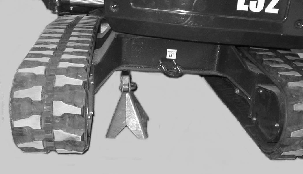
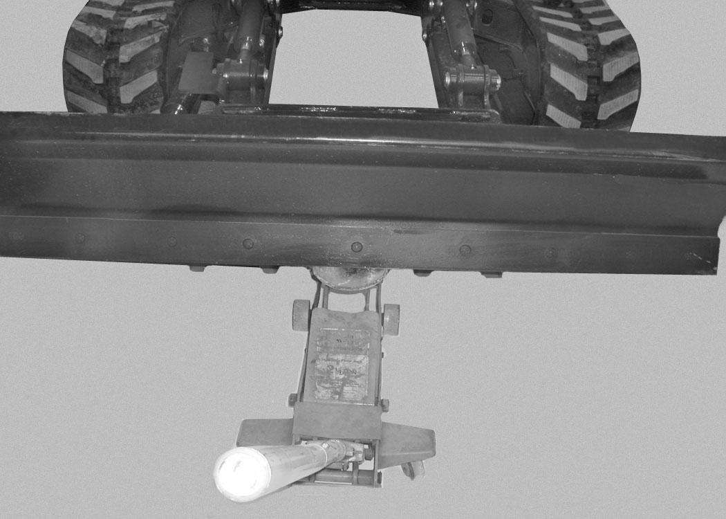
Track Tension
NOTE: The wear of the pins and bushings on the undercarriage vary with the working conditions and the different types of soil conditions. It is necessary to inspect track tension and maintain the correct tension. See SERVICE SCHEDULE for the correct service interval. (See SERVICE SCHEDULE on Page 153.)
Adjusting
Figure 336
Warning
AVOID INJURY
Keep fingers and hands out of pinch points when checking the track tension.
W-2142-0903
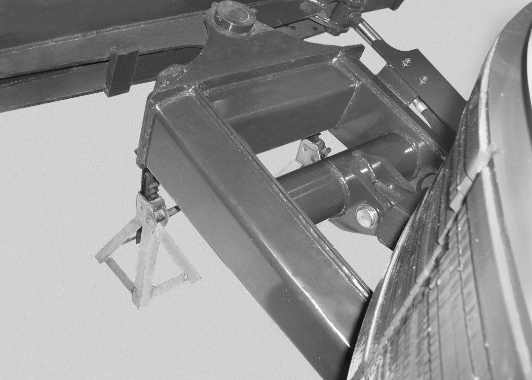
Raise one side of the machine (Approximately four inches) using the boom and arm.
Raise the blade fully and install jackstands under the blade and track frame (Item 1) [Figure 336]. Lower the boom until all machine weight is on the jackstands.
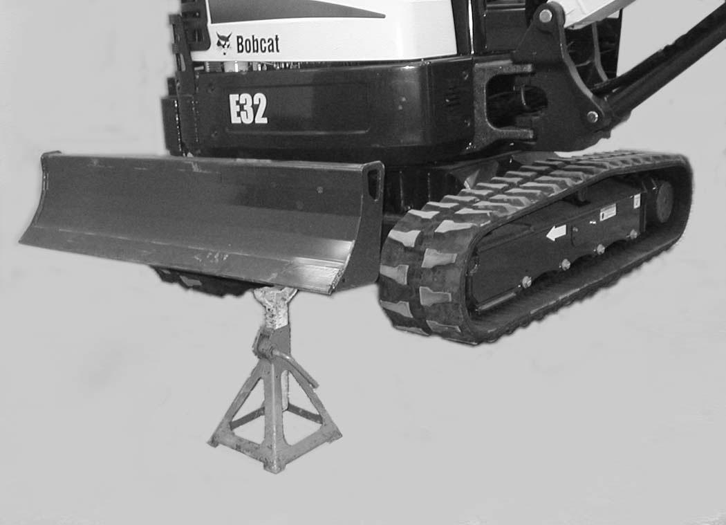
Stop the engine.
TRACK TENSION (CONT’D)
Adjusting (Cont’d)
Rubber Track Clearance
Figure 337
338
10 - 15 mm (0.39 - 0.59 in)
10 - 15 mm (0.39 - 0.59 in)
Steel Track Clearance
Figure 339
17,3 - 30 mm (0.68 - 1.18 in)
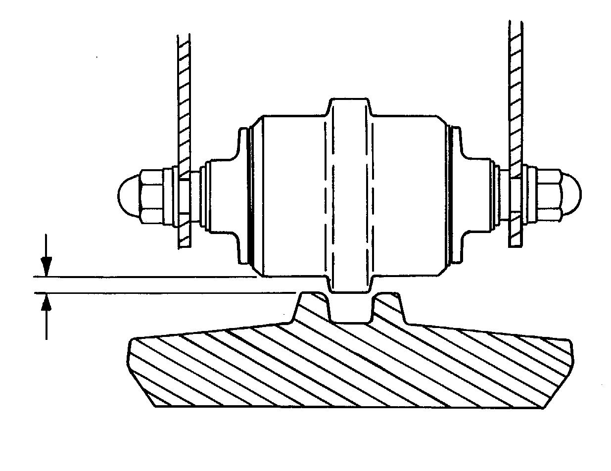
Measure the track clearance at the middle track roller. Do not get fingers into pinch points between the track and the track roller. Us a bolt or dowel of the appropriate size to check the gap between the contact edge of the roller and the top edge of the track guide [Figure 339]
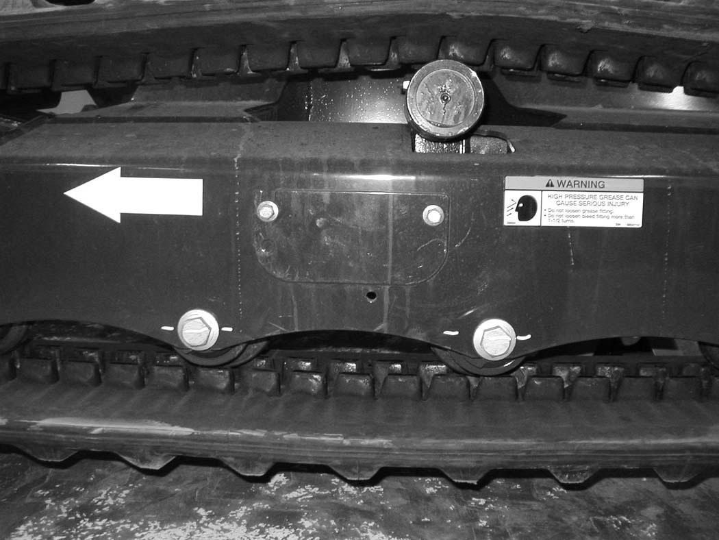
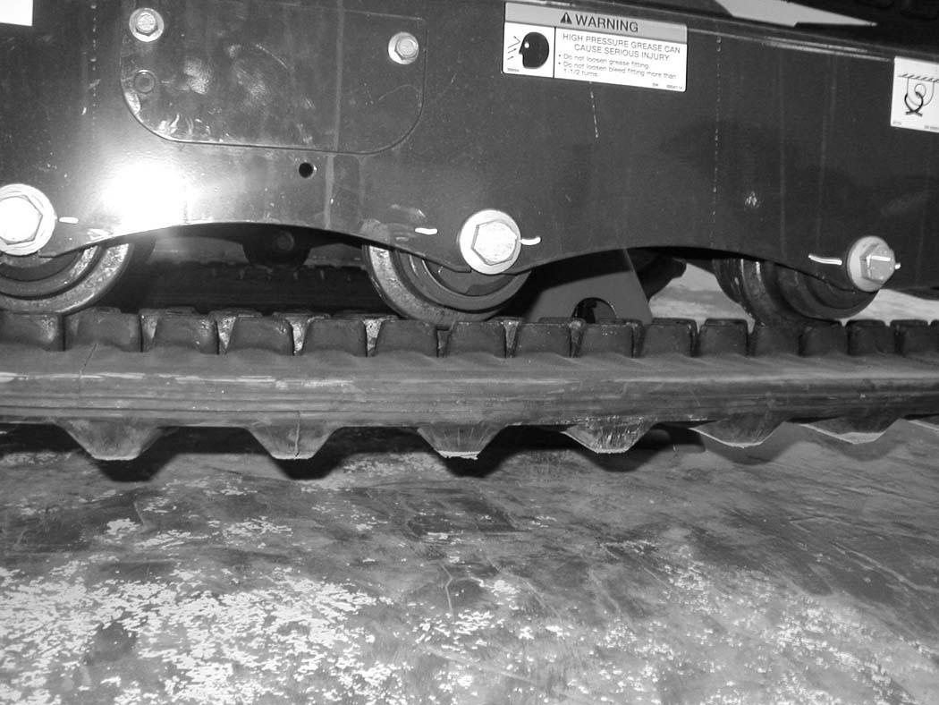
Steel Track Clearance - 17,3 - 30 mm (0.68 - 1.18 in).
Measure the clearance at the middle track roller. Do not get fingers into pinch points between the track and the track roller. Use a bolt or a dowel of the appropriate size to check the gap between the contact edge of the roller and the top edge of the track guide [Figure 337] and [Figure 338].
Rubber Track Clearance - 10 - 15 mm (0.39 - 0.59 in).
TRACK TENSION (CONT’D)
Adjusting (Cont’d)
Warning
HIGH PRESSURE GREASE CAN CAUSE SERIOUS INJURY •Do not loosen the track tension fitting more than 1 - 1/2 turns.
W-2994-0515
With Bleed Screw and Track Tension Fitting
Figure 341
Add grease to the track tension fitting (Item 1) [Figure 341] until the track tension is correct.
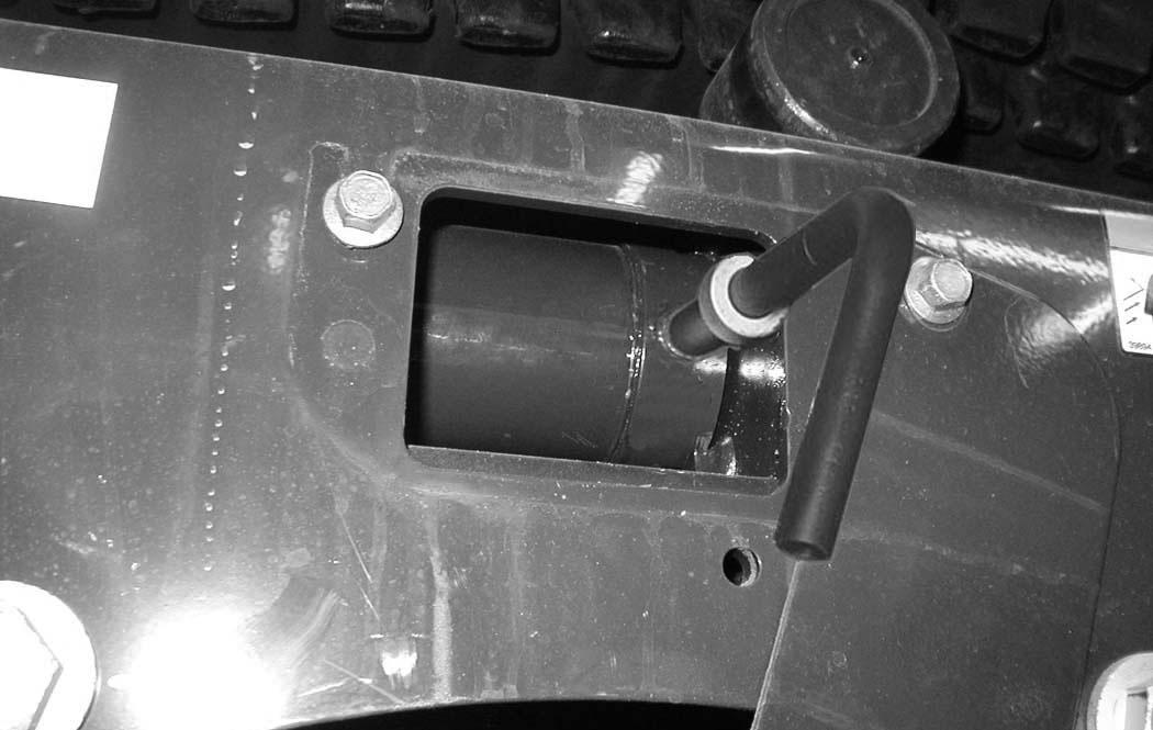
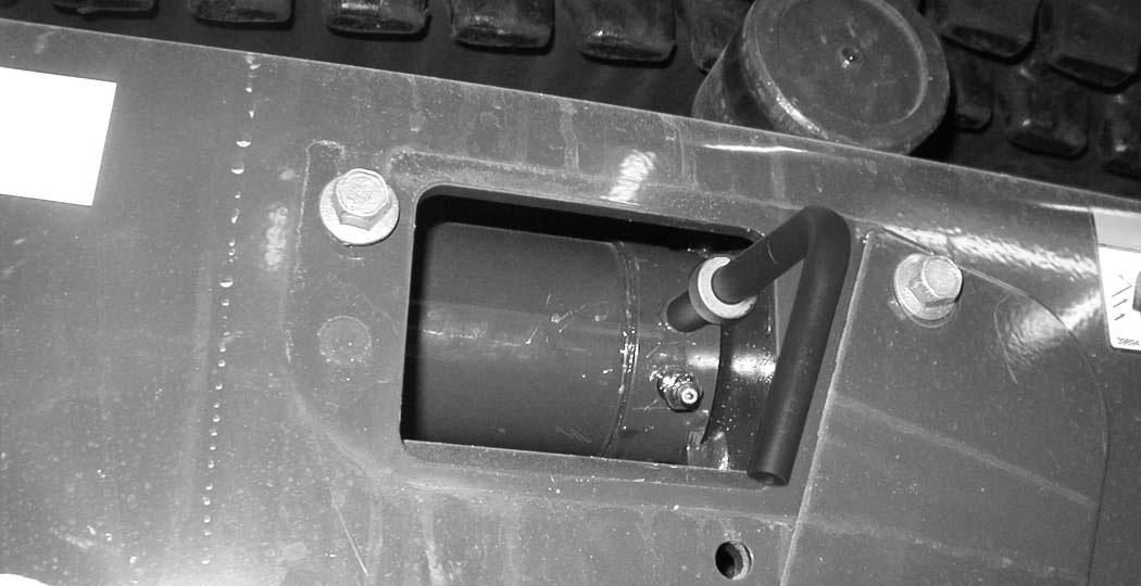
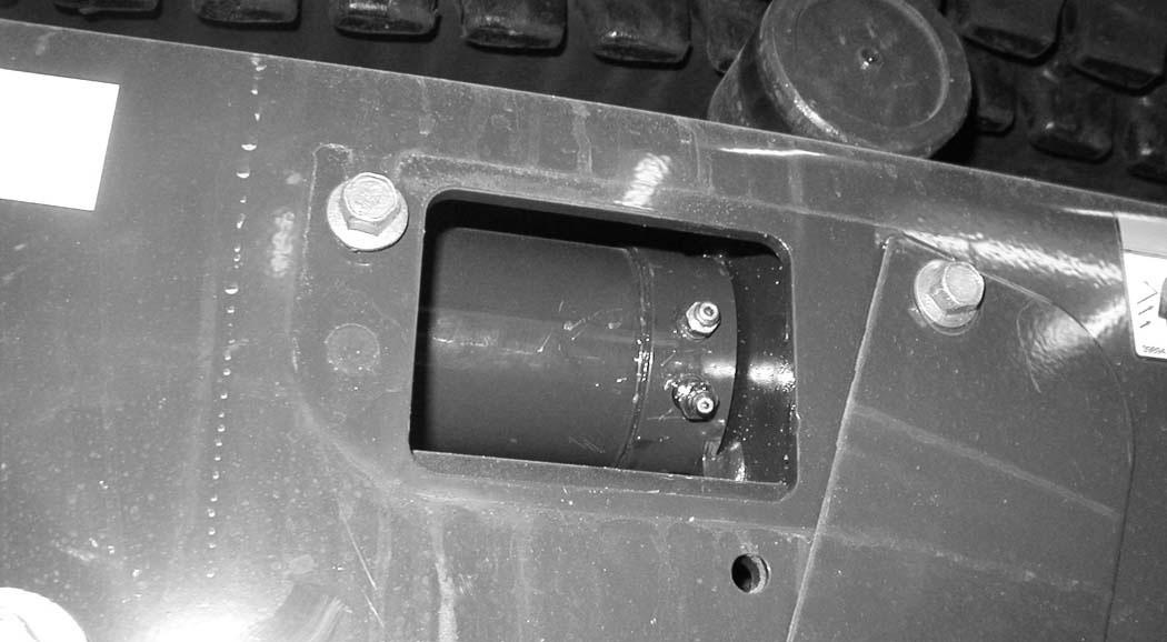
Figure 342
The tension removal tool (P/N 6675936) is available and recommended to direct the flow of grease to aid in cleanup. Always dispose of the grease in an environmentally friendly manner.
Use tool 6675936 (Item 1) [Figure 342] to loosen the bleed fitting (Item 2) [Figure 341] to release tension from the track. Do not loosen the bleed fitting more than 1-1/2 turns.
The tool is sized to fit the bleed fitting (Item 2) [Figure 341]
NOTE: Do not loosen the track tension fitting (Item 1) [Figure 341].
Repeat the procedure for the opposite side.
With One Piece - Track Tension Fitting
Figure 343
Add grease to the track tension fitting (Item 1) [Figure 343] until the track tension is correct.
The tension removal tool (P/N 7277225) is available and recommended to direct the flow of grease to aid in cleanup. Always dispose of the grease in an environmentally friendly manner.
Use tool 7277225 (Item 1) [Figure 344] to loosen the track tension fitting (Item 1) [Figure 343] to release tension from the track.
The tool is sized to fit the one piece track tension fitting (Item 1) [Figure 343]
NOTE: Do not loosen the track tension fitting (Item 1) [Figure 343] more than 1-1/2 turns.
Installation: Tighten the track tension fitting to 24 - 30 N•m (18 - 22 ft-lb) torque.
Repeat the procedure for the opposite side.
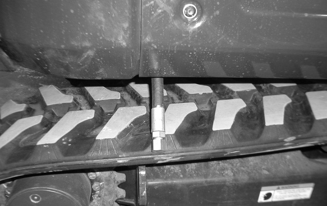
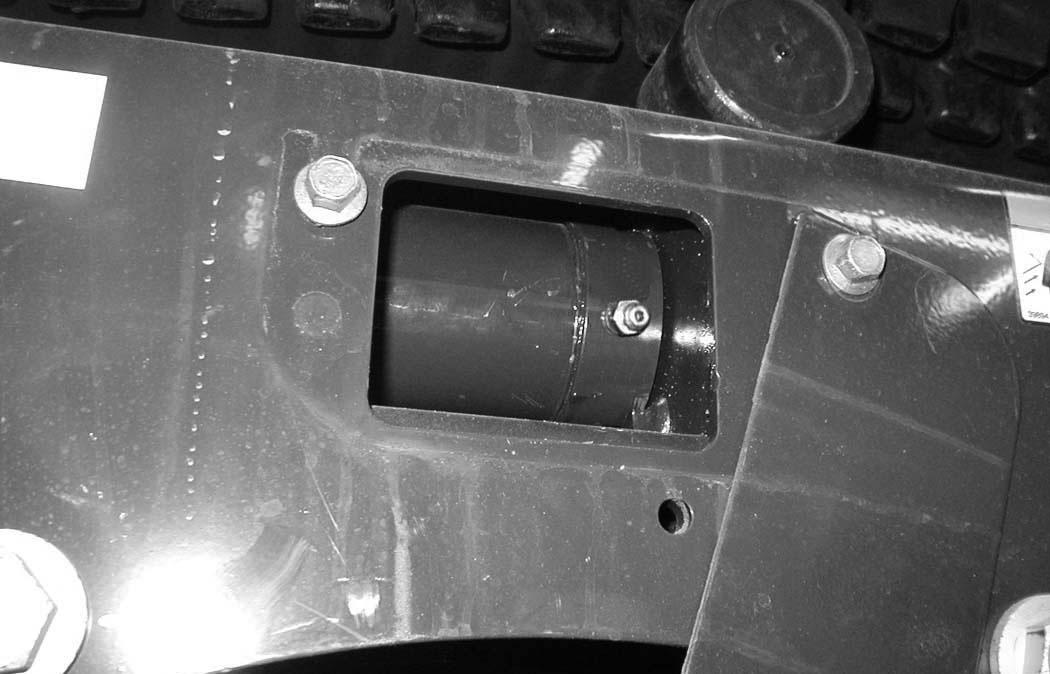
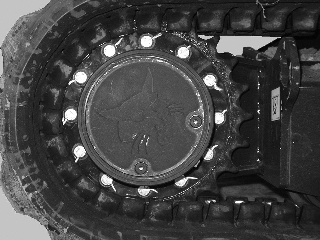
Travel Motor
Checking And Adding Oil
Figure 345
Park the excavator on a level surface with the plugs (Items 1 and 2) [Figure 345] positioned as shown.
Remove the plug (Item 1) [Figure 345]. The lube level must be at the bottom edge of the hole.
Add lubricant (SAE 90W) through the hole (Item 1) [Figure 345] if the lube level is low.
Repeat the procedure for the opposite travel motor.
Removing And Replacing Oil
See the SERVICE SCHEDULE for the correct service interval. (See SERVICE SCHEDULE on Page 153.)
Warning
Avoid Injury Or Death
Always clean up spilled fuel or oil. Keep heat, flames, sparks or lighted tobacco away from fuel and oil. Failure to use care around combustibles can cause explosion or fire.
W-2103-0508
Park the excavator on a level surface with plugs (Items 1 and 2) [Figure 345] positioned as shown. Remove both plugs and drain the lubricant into a container.
Install the bottom plug (Item 2). Add lubricant (SAE 90W) through the plug hole (Item 1) [Figure 345] until the lube level is at the bottom edge of the hole. (See Capacities on Page 232.)
Install the plug (Item 1) [Figure 345].
Repeat the procedure for the opposite travel motor.
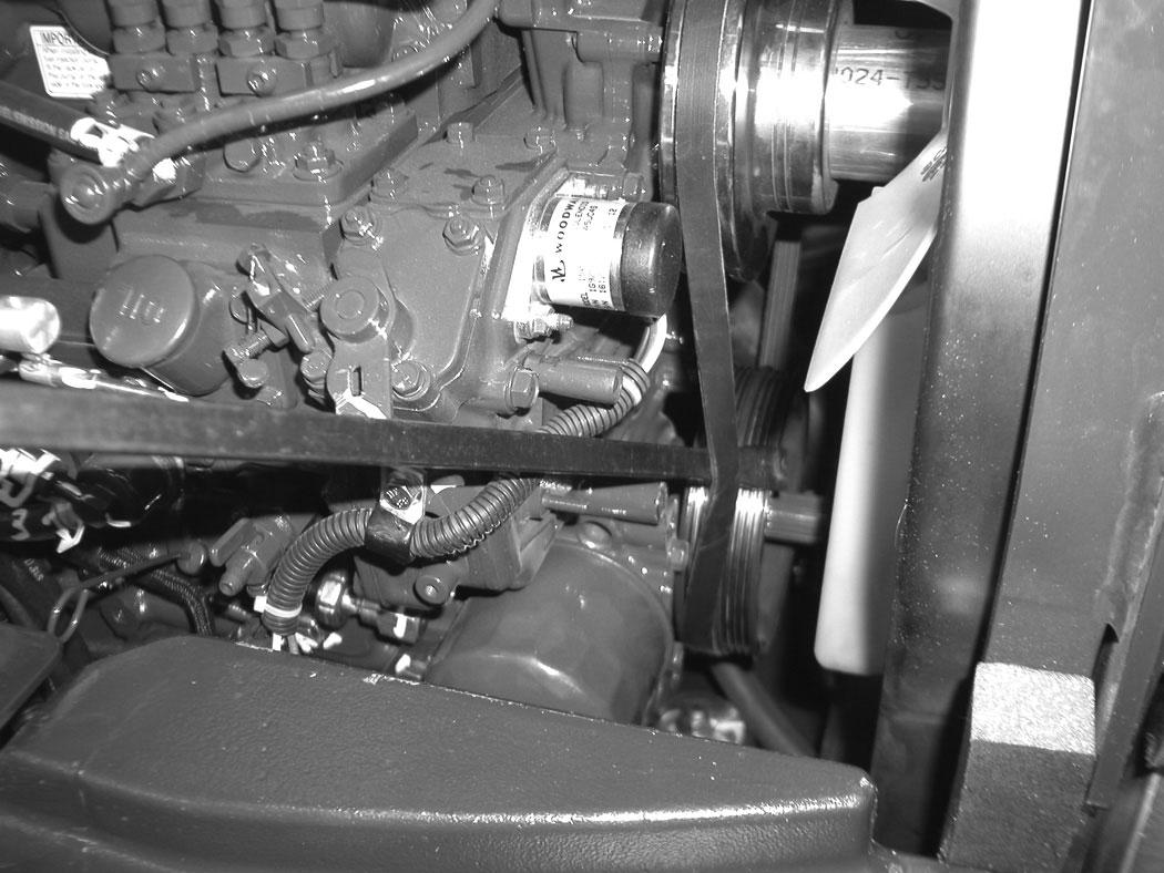
Alternator Belt
Belt Adjustment
The alternator belt is a special maintenance free type that is pretensioned over the pulleys. This belt eliminates the need for a tensioning device and does not require periodic adjustment. Contact your Bobcat dealer for replacement parts.
Belt Replacement
Stop the engine and open the tailgate. (See TAILGATE on Page 159.)
NOTE:If the machine is equipped with air conditioning, the compressor belt will need to be removed before the alternator belt can be removed.
The engine will need to be rotated by hand to remove the belt. To access the flywheel, remove the plug (Item 1) [Figure 347] from the flywheel housing. (A pry bar will be needed to rotate the flywheel to assist in belt removal and installation.)
Remove the air conditioning compressor belt (if equipped). (See AIR CONDITIONING COMPRESSOR BELT on Page 190.)
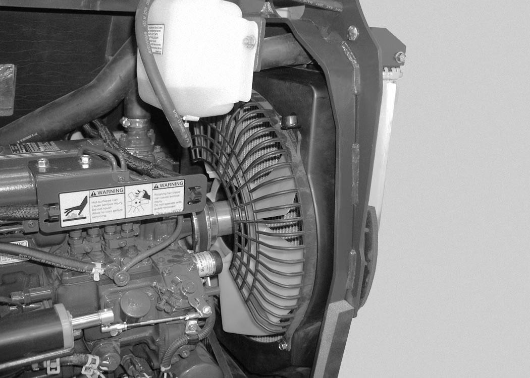
Remove the three bolts (Item1) and remove the fan guard (Item 2) [Figure 346].
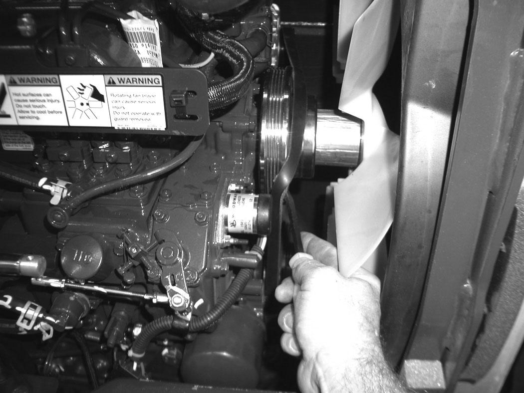
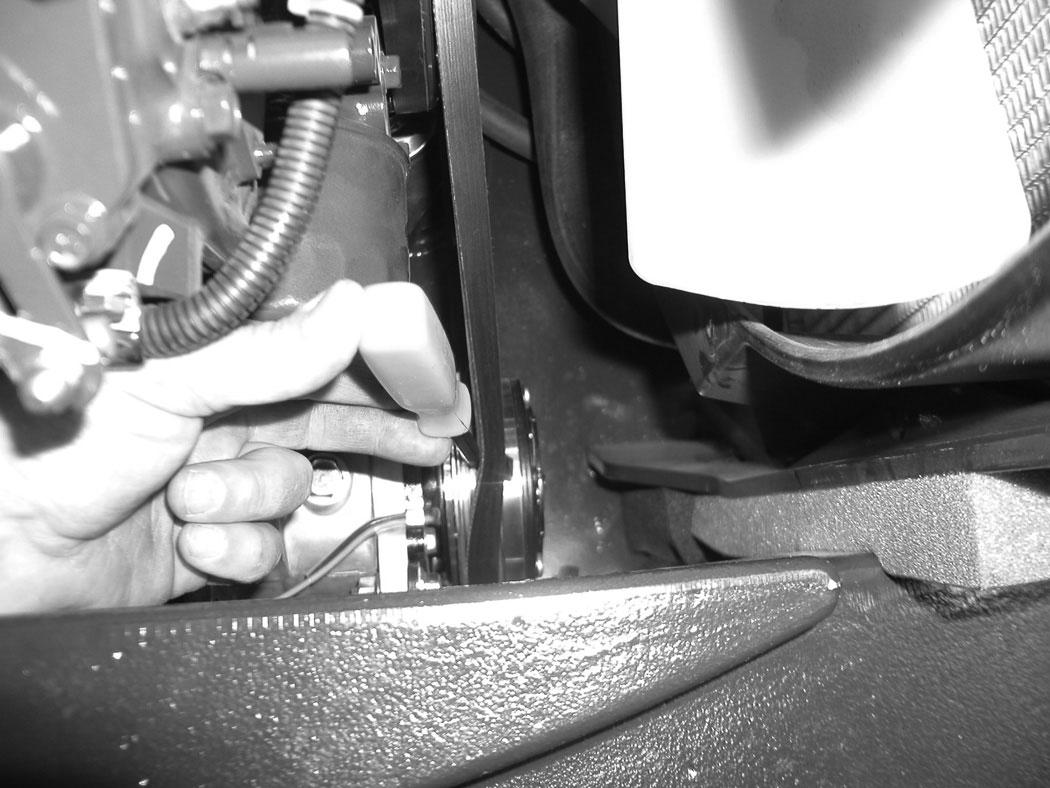
Use a pry bar between the belt and the crankshaft pulley (Item 1) [Figure 348].
Using a pry bar on the flywheel, rotate the engine by hand to push the belt off the crankshaft pulley. Continue to rotate the flywheel until the belt is loose.
ALTERNATOR BELT (CONT’D)
Belt Replacement (Cont’d)
Installation
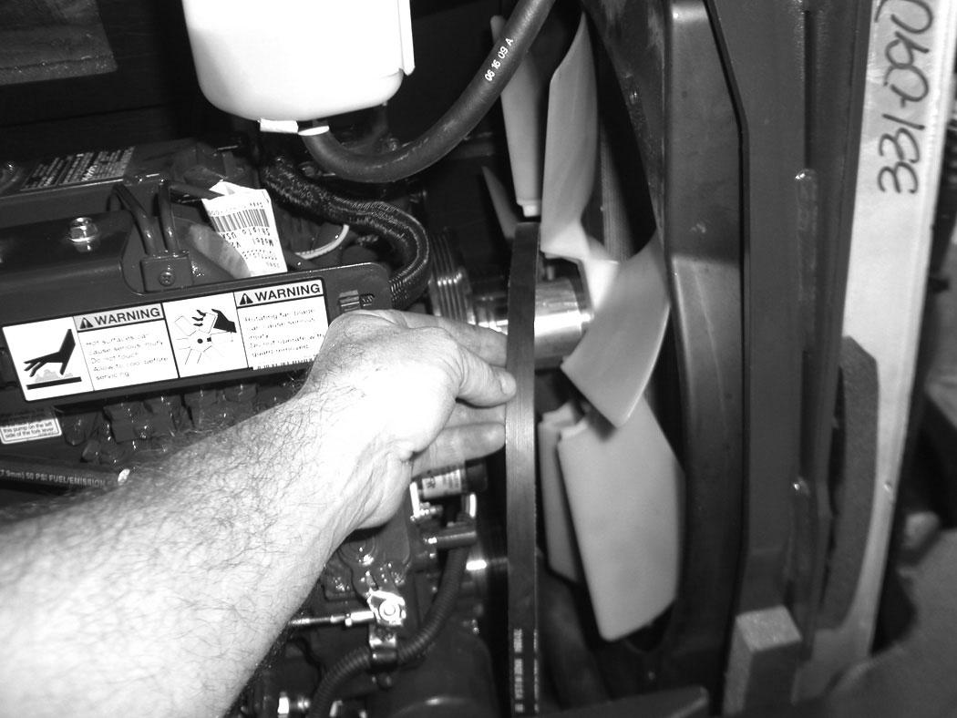
Position the belt (Item 1) [Figure 349] over the fan blades.
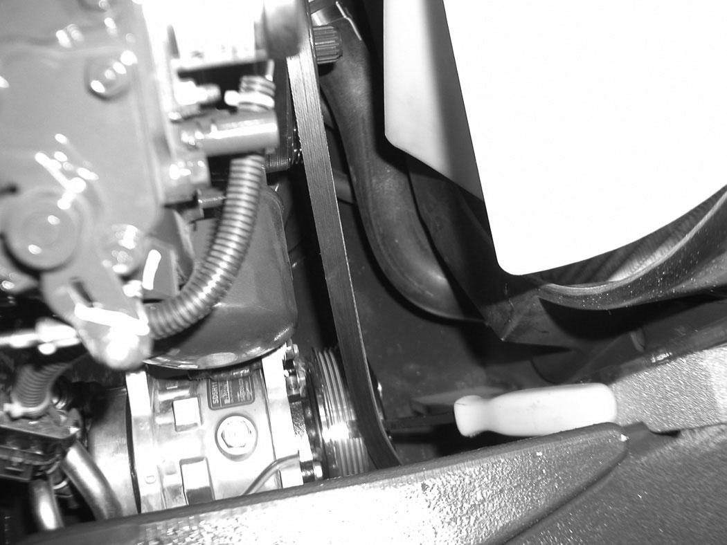
Install the belt (Item 1) [Figure 350] over the alternator pulley, the crankshaft pulley and over the fan spacer.
Use a pry bar (Item 2) [Figure 350] to position the belt onto the fan pulley.
Using a pry bar, rotate the flywheel by hand while using the second pry bar to install the belt over the fan pulley.
Continue to rotate the engine by hand until the belt is fully on the pulleys.
Reinstall the rubber plug (Item 1) [Figure 347].
Install the fan guard (Item 2) with the three bolts (Item1) [Figure 346]
Close the tailgate.
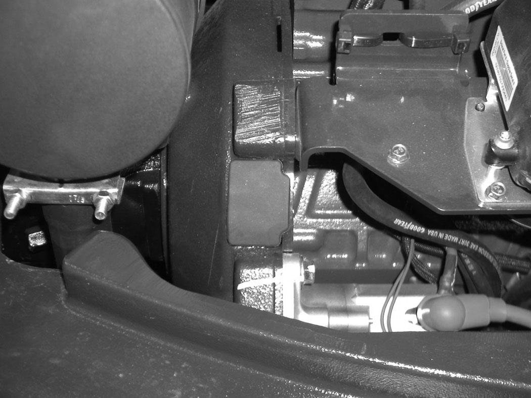
Air Conditioning Compressor Belt
Belt Adjustment
The compressor belt is a special maintenance free type that is pretensioned over the pulleys. This belt eliminates the need for a tensioning device and does not require periodic adjustment. Contact your Bobcat dealer for replacement parts.
Belt Replacement
Stop the engine and open the tailgate. (See TAILGATE on Page 159.)
The engine will need to be rotated by hand to remove the belt. To access the flywheel, remove the plug (Item 1) [Figure 351] from the flywheel housing.
Position the belt (Item 1) [Figure 353] over the crankshaft pulley and to the compressor pulley.
Use a pry bar (Item 2) [Figure 353] to position the belt on the pulley while using the second pry bar at the flywheel to rotate the engine by hand.
Continue to rotate the engine by hand until the belt is fully on the pulleys.
Reinstall the rubber plug (Item 1) [Figure 351]
Close the tailgate.
Use a pry bar (Item 1) [Figure 352] to push the belt off of the pulley. Using a pry bar on the flywheel, rotate the engine by hand to push the belt off the crankshaft pulley. Continue to rotate the flywheel until the belt is loose. Remove the belt.
X-CHANGE
Inspection And Maintenance
Figure 354
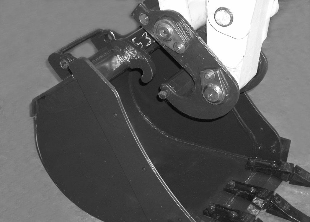
Inspect the X-Change for wear or damage. Inspect the XChange pins (Item 1) and hooks (Item 2) [Figure 354] (on the attachment) for wear or damage.
Repair or replace damaged parts.
Pin Grabber Quick Coupler
Inspection And Maintenance
Figure 355
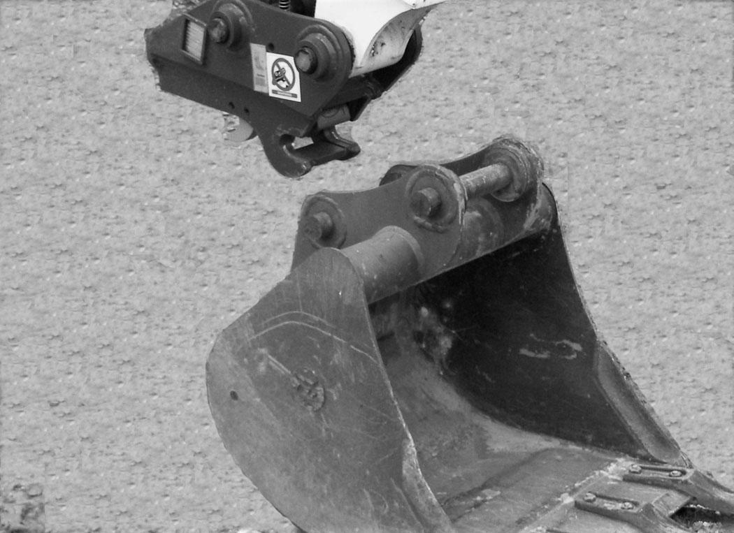
Inspect the pin grabber clasps (Item 1) and the pins (Item 2) [Figure 355] (on the attachment) for wear or damage.
Repair or replace damaged parts.
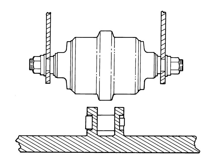
Track Roller And Idler Lubrication
Procedure
The track rollers and idlers require no maintenance. The bearings are a sealed design.
Bucket Teeth Removal And Installation
Warning
Wear safety glasses to prevent eye injury when any of the following conditions exist:
•Pressurized fluids and springs or other stored energy components.
•Flying debris or loose material is present.
•Engine is running.
•Tools are being used.
W-2505-0604
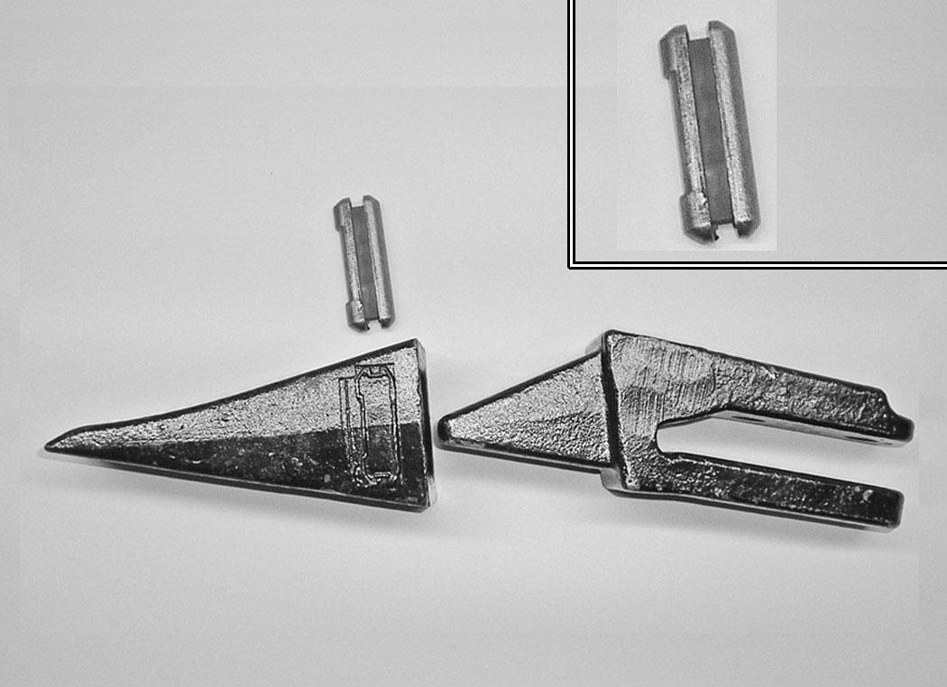
Position the bucket so the bucket teeth are at a 30° angle up from the ground for accessibility to the teeth.
Lower the boom until the bucket is fully on the ground. Stop the engine and exit the excavator.
The retaining pin (Item 1) must be installed as shown [notch (Item 2) to the front] for proper fit and tooth retention. The side of the tooth point (Item 3) [Figure 356] also shows the correct orientation of the retaining pin.
Installation: Position the new tooth point on the shank and install a new retaining pin. Install the retaining pin until it is flush with the top of the point.
CUTTING EDGE (ANGLE BLADE ONLY)
Removal And Installation
Raise the blade fully and install jackstands (Item 1) [Figure 357] under the blade arms.
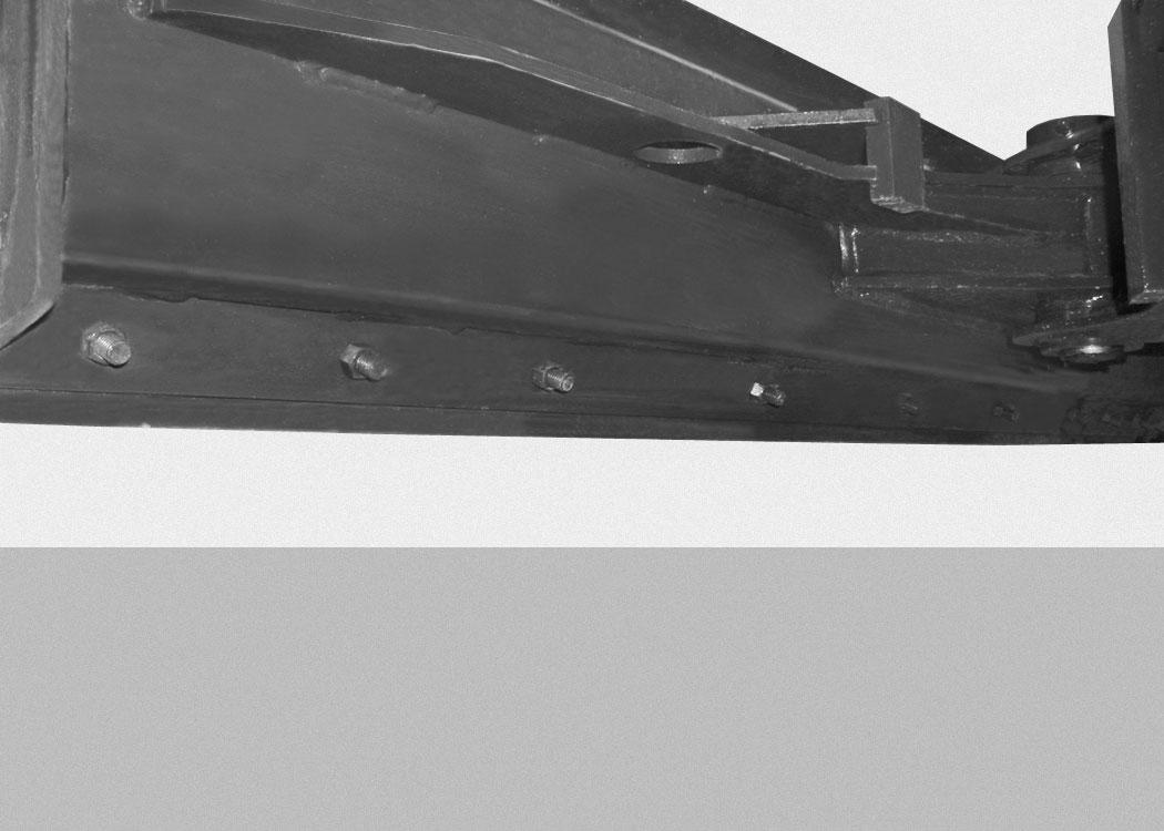
Remove the seven nuts (Item 1) [Figure 359] and bolts from the cutting edge.
Lower the jack and remove the cutting edge.
Installation: Tighten nuts to 125 N•m (90 ft-lb) torque.
NOTE:Cutting edge is reversible and replaceable.
LUBRICATION OF THE HYDRAULIC EXCAVATOR
Lubrication Locations
Lubricate the excavator as specified in the SERVICE SCHEDULE for the best performance of the machine. (See SERVICE SCHEDULE on Page 153.)
Always use a good quality lithium based multipurpose grease when lubricating the machine. Apply the lubricant until extra grease shows.
NOTE:Use Extra Heavy Gear Shield grease for grease fittings (Item 20, 21 and 22).
Lubricate the following locations on the excavator EVERY 8 - 10 HOURS:
Ref Description (# of Fittings)
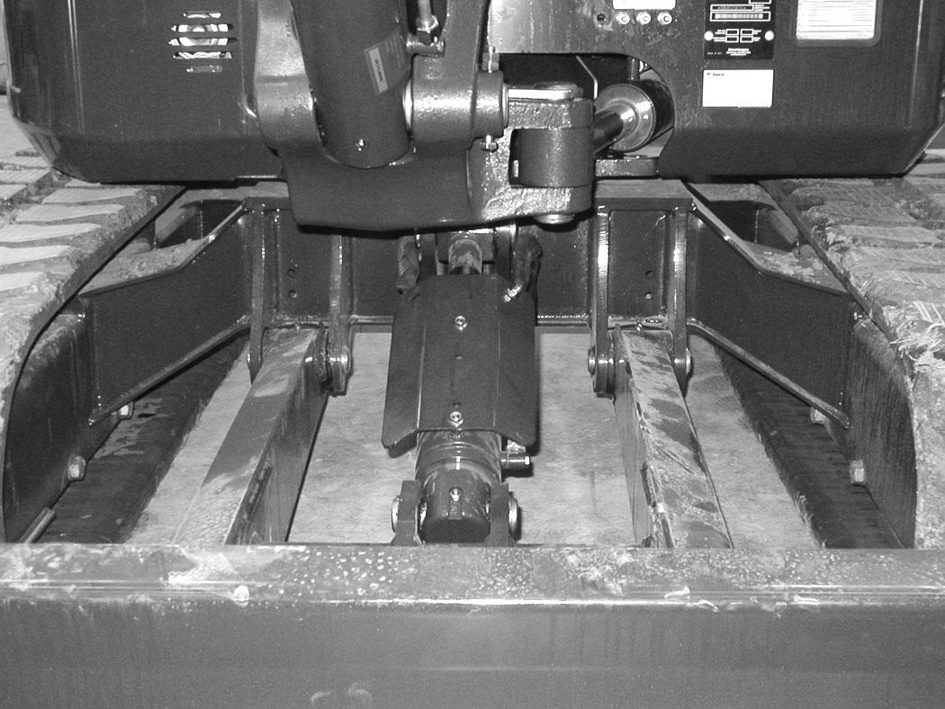
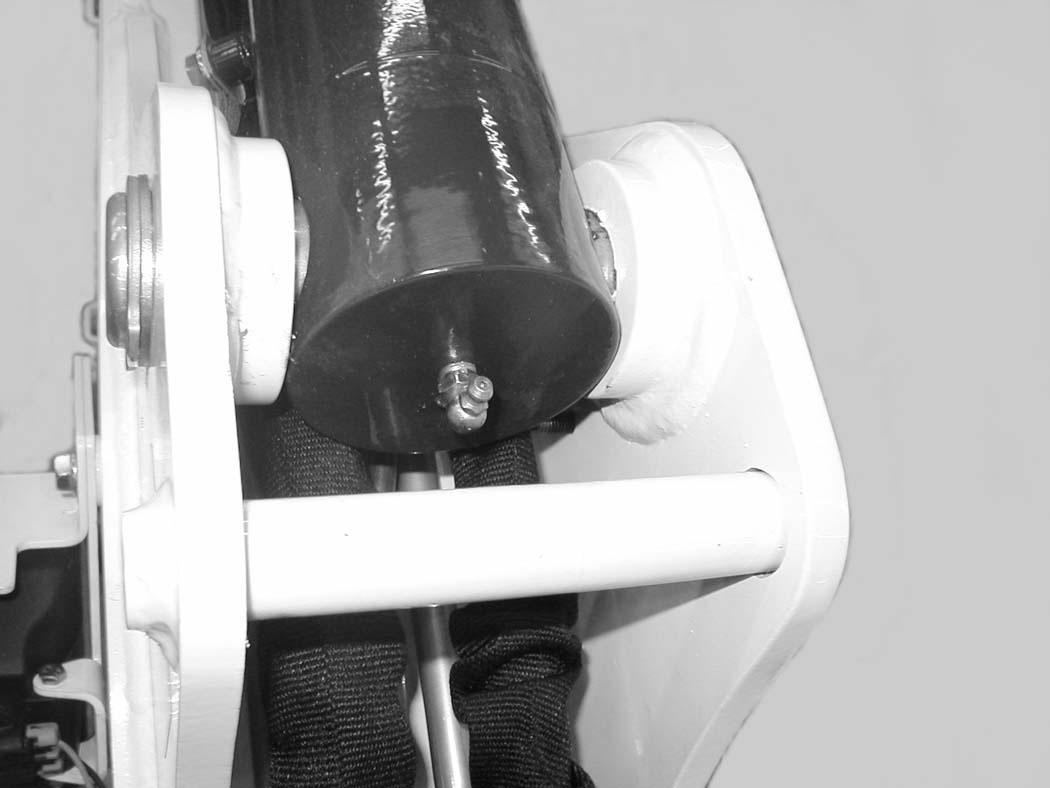
1.Blade Cylinder Rod End (1) [Figure 360]
2.Blade Cylinder Base End (1) [Figure 360]
3.Blade Pivots (2) [Figure 360]
4.Boom Cylinder Base End (1) [Figure 360]
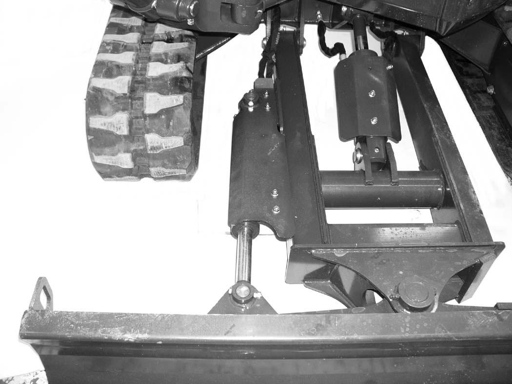
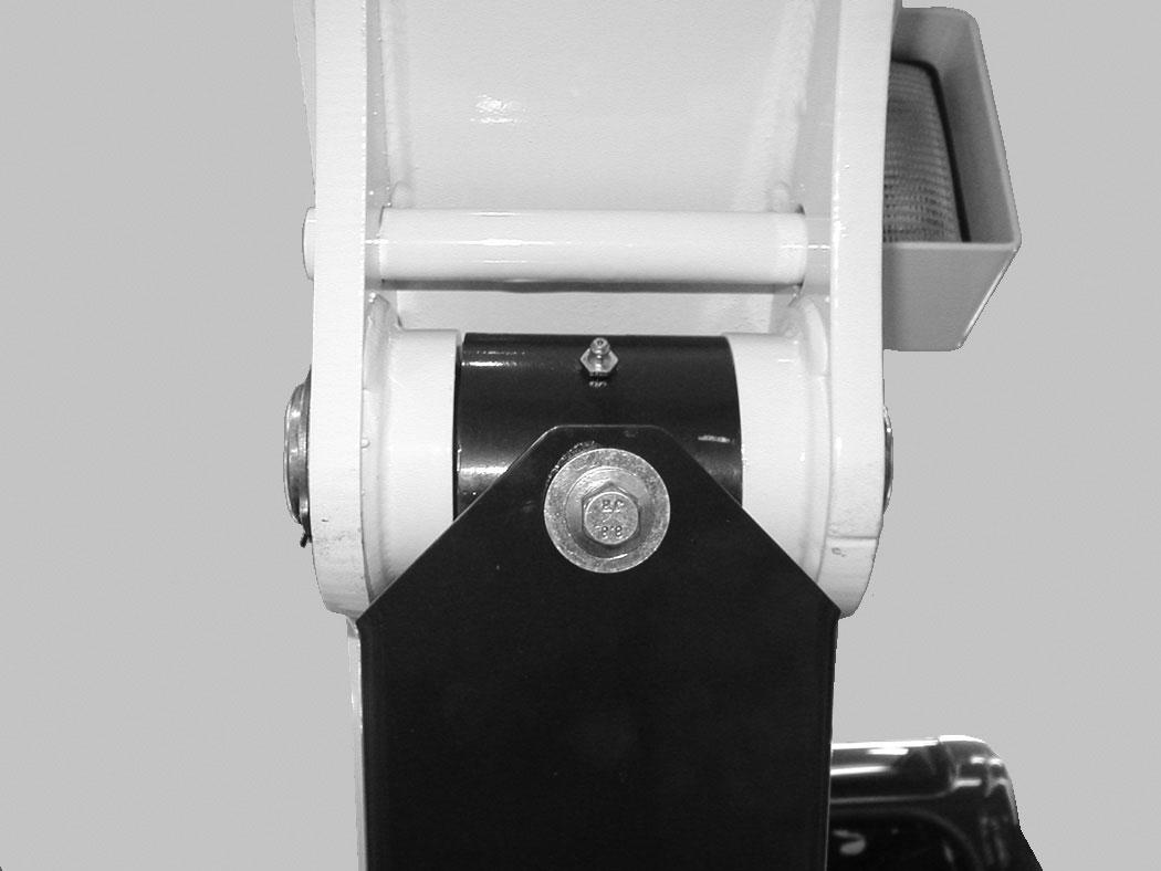
5.Angle Blade Cylinder Rod End (1) [Figure 361] (If Equipped)
6.Angle Blade Cylinder Base End (1) [Figure 361] (If Equipped)
7.Angle Blade Pivot (1) [Figure 361] (If Equipped)
LUBRICATION OF THE HYDRAULIC EXCAVATOR (CONT’D)
Lubrication Locations (Cont’d)
LUBRICATION OF THE HYDRAULIC EXCAVATOR (CONT’D)
Lubrication Locations (Cont’d)
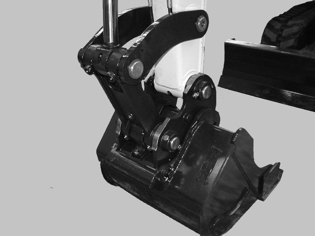
Figure 367
15.Bucket Cylinder Rod End (1) [Figure 367]
16.Bucket Link Pin (1) [Figure 367]
17.Bucket Pivot (3) [Figure 367]
18.Bucket Link - without extendable arm (2), with extendable arm (4) [Figure 367]
19.Arm (1) [Figure 367]
Figure 368
Lubricate the following locations on the hydraulic excavator EVERY 50 HOURS:
NOTE:Use Extra Heavy Gear Shield grease for grease fittings (Item 20, 21 and 22).
20.Swing Circle (1) [Figure 368]
21.Swing Pinion (1) [Figure 368]. (Install 3 to 4 pumps of grease then rotate the upperstructure 90°. Install 3 to 4 pumps of grease and again rotate the upperstructure 90°. Repeat this until the slew pinion has been greased at four positions.)
Lubricate the following location on the hydraulic excavator EVERY 1000 HOURS:
NOTE:Use Extra Heavy Gear Shield grease for grease fittings (Item 20, 21 and 22).
22.Boom Swing Cylinder Base (1) [Figure 369]
NOTE:The boom swing grease fitting is located on the side of base end of the cylinder.