17 minute read
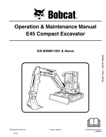
CONTROL CONSOLE LOCKOUTS


Inspection And Maintenance
Figure 277
When the left console is raised [Figure 277], the hydraulic control levers (joysticks) and traction system must not function.
Sit in the operator's seat, fasten the seat belt and start the engine.
Raise the left console [Figure 277]
Move the joystick control levers. There should be no movement of the boom, arm, slew or bucket.
Move the steering control levers. There should be no movement of the excavator tracks.
Service the system if these controls do not deactivate when the left control console is raised. (See your Bobcat dealer for service.)
Failure to properly inspect and maintain the seat belt can cause lack of operator restraint resulting in serious injury or death.
W-2466-0703
Check the seat belt daily for correct function.
Inspect the seat belt system thoroughly at least once each year or more often if the machine is exposed to severe environmental conditions or applications.
Any seat belt system that shows cuts, fraying, extreme or unusual wear, significant discolorations due to ultraviolet UV exposure, dusty / dirty conditions, abrasion to the seat belt webbing, or damage to the buckle, latch plate, retractor (if equipped), hardware or any other obvious problem should be replaced immediately.
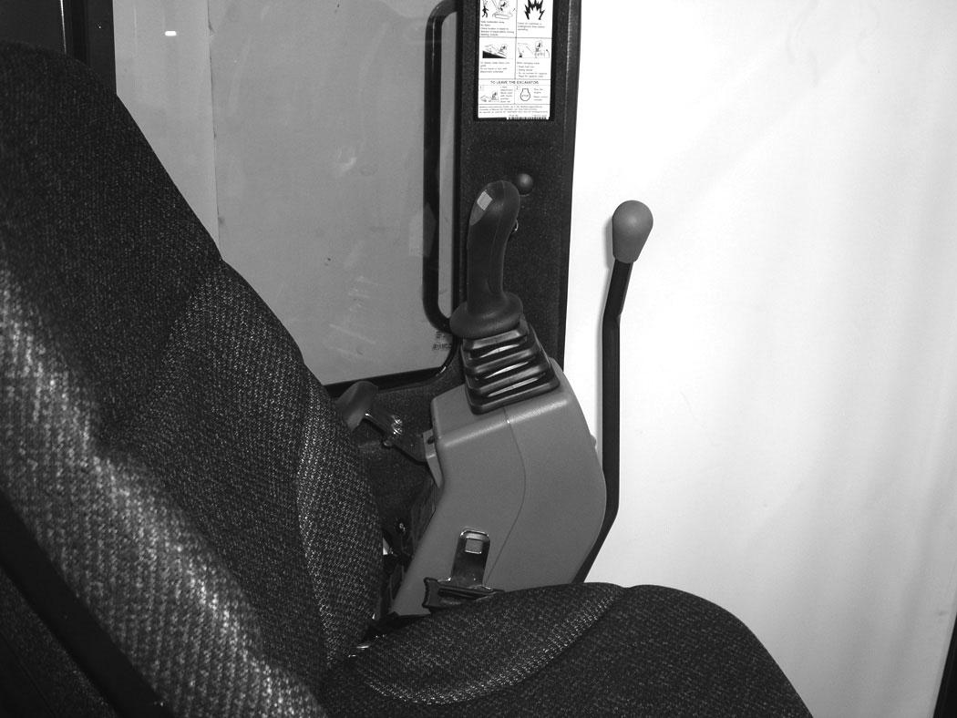
The items below are referenced in [Figure 278].
1.Check the webbing. If the system is equipped with a retractor, pull the webbing completely out and inspect the full length of the webbing. Look for cuts, wear, fraying, dirt and stiffness.
2.Check the buckle and latch for correct operation. Make sure latch plate is not excessively worn, deformed or buckle is not damaged or casing broken.
3.Check the retractor web storage device (if equipped) by extending webbing to determine if it looks correct and that it spools out and retracts webbing correctly.
4.Check webbing in areas exposed to ultraviolet (UV) rays from the sun or extreme dust or dirt. If the original color of the webbing in these areas is extremely faded and / or the webbing is packed with dirt, the webbing strength may have deteriorated.
See your Bobcat dealer for seat belt system replacement parts for your machine.
MOTION ALARM SYSTEM Description
This excavator may be equipped with a motion alarm system. The motion alarm will sound when the operator moves the travel control levers in either the forward or reverse direction. Slight movement of the steering levers in either the forward or reverse direction is required with hydraulic components before the motion alarm will sound.
Warning
Avoid Injury Or Death
When an engine is running in an enclosed area, fresh air must be added to avoid concentration of exhaust fumes. If the engine is stationary, vent the exhaust outside. Exhaust fumes contain odorless, invisible gases which can kill without warning.
Sit in the operator’s seat and fasten the seat belt. Start the engine. (See PRE-STARTING PROCEDURE on Page 68.)
Move the travel control levers (one lever at a time) in the forward direction. The motion alarm must sound. Move the travel control levers (one lever at a time) in the reverse direction. The motion alarm must sound.
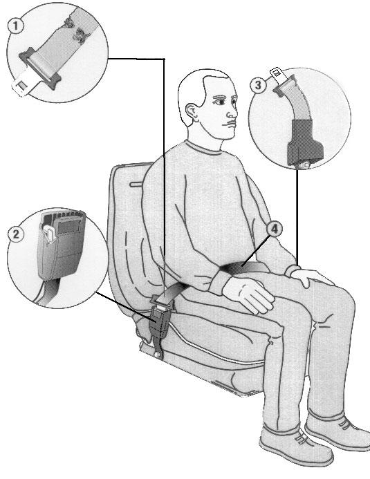
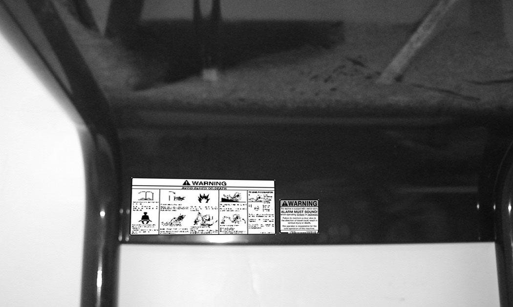
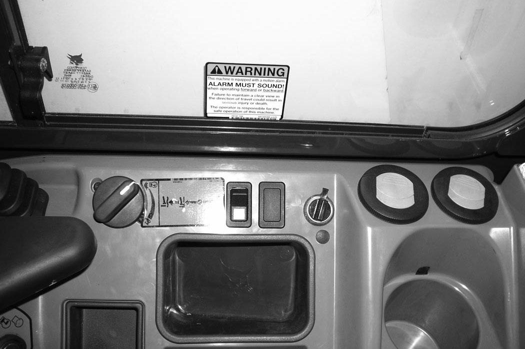
Inspect for damaged or missing motion alarm decal (Item 1) [Figure 279] (cab machine) or (Item 1) [Figure 280] (canopy machine). Replace if required.
NOTE:The excavator will need to be moved slightly in both the forward and reverse direction to test the motion alarm. Keep all bystanders away from machine during test.
Slightly move both travel control levers in the forward direction (until the machine is slowly moving forward) and then press the motion alarm cancel switch (Item 1) [Figure 281]. The motion alarm will shut off. With the machine still moving forward, move one of the levers to the NEUTRAL position, the motion alarm must sound.
Slightly move both travel control levers in the reverse direction (until the machine is slowly moving backward) and then press the motion alarm cancel switch (Item 1) [Figure 281] (the switch icon will be illuminated when the motion alarm is deactivated). The motion alarm will shut off. With the machine still moving backward, move one of the levers to the NEUTRAL position, the motion alarm must sound.
Return both levers to NEUTRAL and turn excavator key to OFF position. Exit the excavator. (See STOPPING THE ENGINE AND LEAVING THE EXCAVATOR on Page 76.)
MOTION ALARM SYSTEM (CONT’D)
Inspecting (Cont’d)
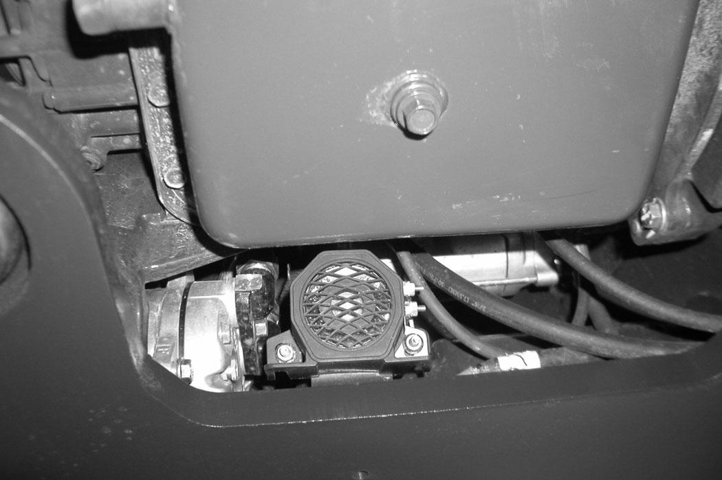
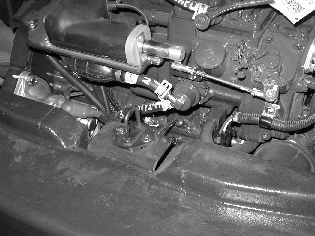
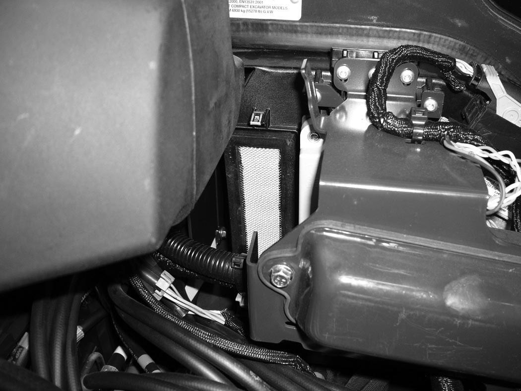
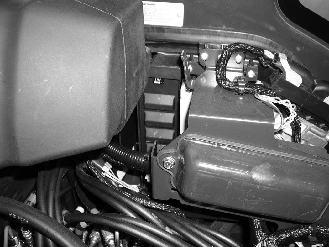
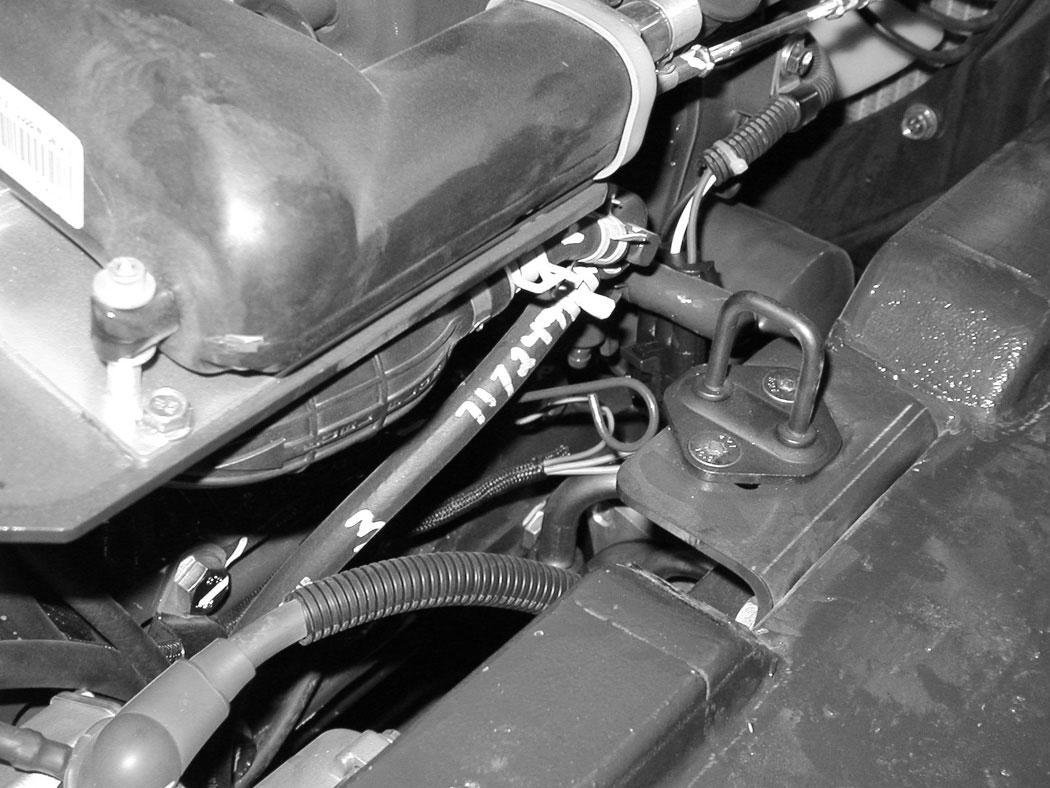
The motion alarm is mounted to the bottom rear of the excavator (to the front of the engine oil pan).
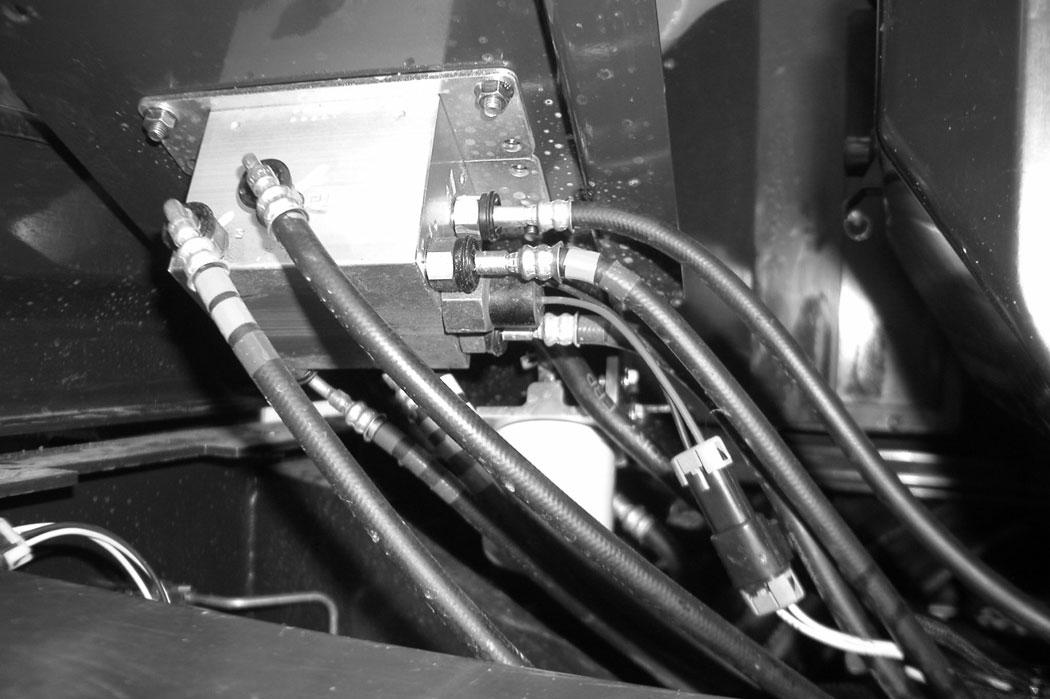
Figure 282
Inspect the motion alarm electrical connections and wire harness (Item 1) [Figure 282], wire harness (Item 1) [Figure 283] and motion alarm switch (Item 2) [Figure 283] for tightness and damage. Repair or replace any damaged components.
If the motion alarm switch requires service, see the following information.
Adjusting Switch Position
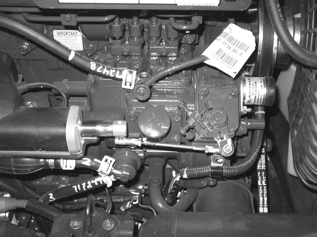
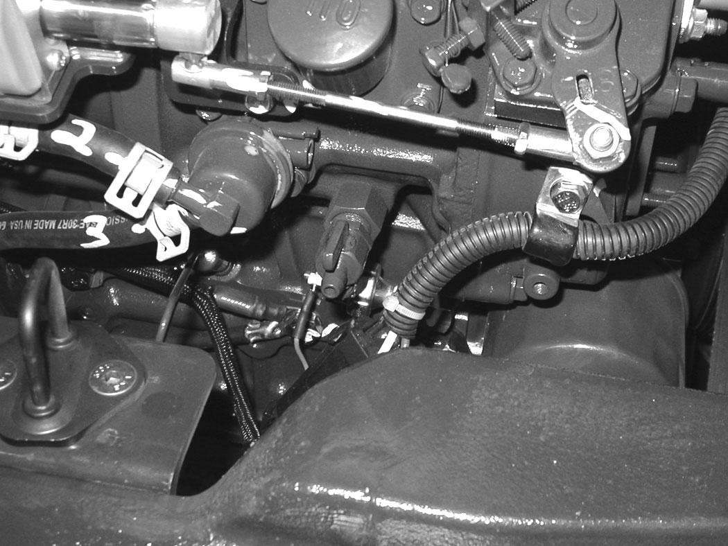
Figure 283
Switch Location
The motion alarm switch (Item 2) [Figure 283] is located in the travel control valve located under the floorplate. Remove the floor mat and the floorplate to access the switch.
The switch (Item 2) [Figure 283] is non-adjustable. It must be fully installed into the travel control valve housings and tightened. Tighten the switch to 18 - 20 N•m (13 - 15 ft-lb).
Inspect the motion alarm system for proper function after switch replacement.
Warning
This machine is equipped with a motion alarm. ALARM MUST SOUND! when operating forward or backward.
Failure to maintain a clear view in the direction of travel could result in serious injury or death.
The operator is responsible for the safe operation of this machine.
Tailgate

Opening And Closing
Warning
Avoid Injury Or Death
Never service or adjust the machine when the engine is running unless instructed to do so in the manual.
Warning
Keep the rear door closed when operating the machine. Failure to do so could seriously injure a bystander.
Adjusting The Latch
NOTE: The tailgate can be locked using the start key.
Right Side Cover
Opening And Closing
Figure 286
Open the tailgate to access the right side cover latch (Item 1) [Figure 286]
Pull the latch handle (Item 1) [Figure 286] out until the right side cover is unlatched.

Figure 287
Raise the right side cover and rotate forward until it is held open by the retainer (Item 1) [Figure 287].
To close the right side cover, lift up on the retainer (Item 1) [Figure 287] while raising the right side cover. Rotate the cover back until it is in the fully closed position. Secure the right side cover with the latch (Item 1) [Figure 286].
CAB FILTERS Cleaning And Maintenance
The recirculation filter and the fresh air filter must be cleaned regularly. (See SERVICE SCHEDULE on Page 153.)
The recirculation filter is located to the right of the operator seat and the fresh air filter is located under the right side cover.
Recirculation Filter
Figure 288
The recirculation filter (Item 1) [Figure 288] is located to the right of the operator’s seat.
289
Pull up on the filter (Item 1) [Figure 289] until removed from the housing.
Shake the filter or use low pressure air to clean the filter. Replace the filter when very dirty or if damaged.
Installation: Position the bottom of the filter (Item 1) [Figure 289] into the housing and slowly push the filter down fully.
Fresh Air Filter
Figure 290
The fresh air filter is located under the right side cover. Open the right side cover. (See RIGHT SIDE COVER on Page 160.)
Pull out on the tab (Item 1) and remove the cover (Item 2) [Figure 290]
Figure 291
Pull the filter (Item 1) [Figure 291] out of the housing.
Shake the filter or use low pressure air to clean the filter. Do not use solvents. Replace the filter when very dirty or damaged.
Installation: Position the filter (Item 1) [Figure 289] into the housing and slowly push the filter in fully.
Place the bottom tabs of the filter cover (Item 2) into the frame and push the top in until the tab (Item 1) [Figure 290] locks to the frame.
HEATING, VENTILATION AND AIR CONDITIONING (HVAC)
Cleaning And Maintenance
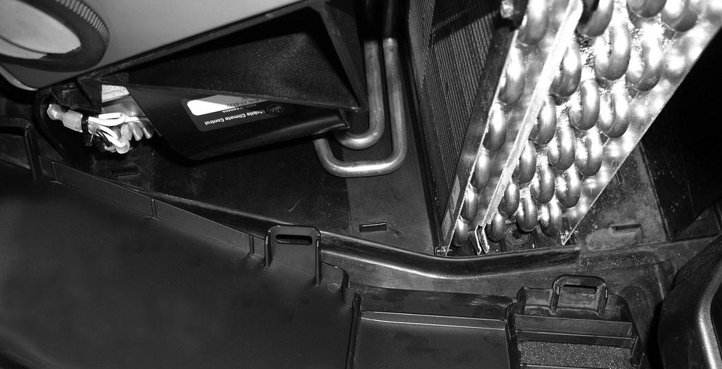
The inside of the HVAC housing needs to be cleaned regularly. Dust will accumulate over time inside the housing. A dusty heater and evaporator coil will reduce heating and cooling efficiency. (See SERVICE SCHEDULE on Page 153.)
The HVAC housing is located to the right of the operator seat.
After the housing has been cleaned and flushed, remove the jackstands and raise the blade so the front of the excavator is flat on the ground. Stop the engine.
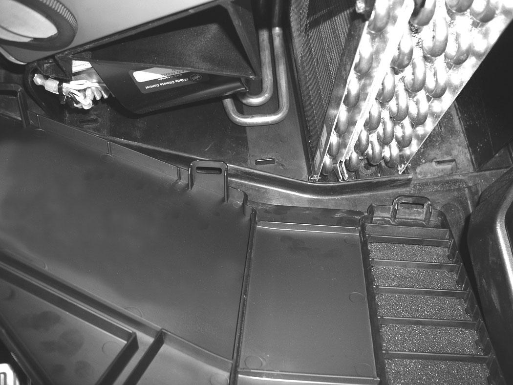
There are three rubber drain valves that allow condensation to drain from the housing during normal air conditioning usage. These drain valve can get clogged with dirt and should be cleaned at the same time the housing is cleaned.
Two of the drain valve can be accessed from the right side cover (the drain valves are located below the HVAC housing on the right side) and one of the valves is located below the left rear corner of the HVAC housing and will be accessed by removing the center floorplate.
Pinch the three rubber drain valves on the flat sides to open the valves and allow dirt and moisture to exit from the end of the valves.
Reinstall the center floorplate and close the right side cover.
Remove the floor mat.
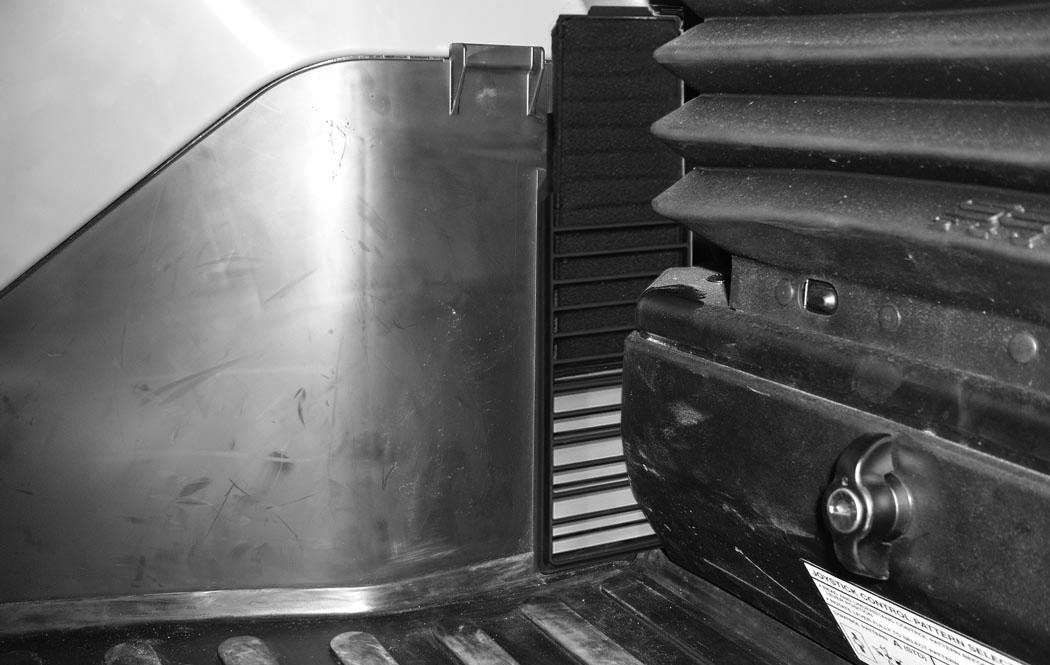
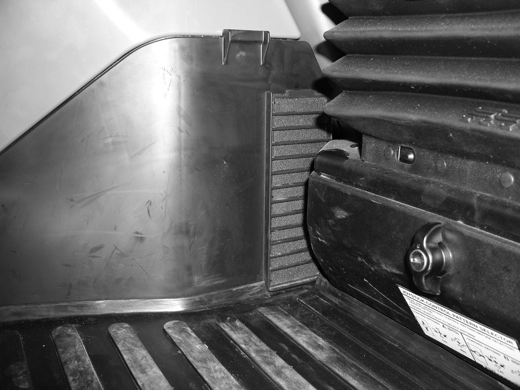
Pull back on the two latches (Item 1) [Figure 292] and remove the HVAC side cover.
To allow water to drain from the HVAC housing during the cleaning process, it is recommended to rotate the upperstructure 90° to the right. Then using the blade, raise the front of the excavator to allow water to run out of the housing. Use jackstands to support the front of the undercarriage.
NOTE:The floor mat needs to be removed to allow easier access for installing the HVAC side cover.
Three tabs (Item 1) are on the bottom of the HVAC housing that the side cover retainers (Item 2) [Figure 294] fit into.
Use a lower pressure air or a low pressure water stream to remove debris and to clean the coils (Item 1) [Figure 293]
Position the side cover on the tabs and starting with the front edge of the side cover, position it into the front of the HVAC housing. Press on the front of the cover to secure the front latch (Item 1) [Figure 292]. Then press in on the top edge of the side cover and work back to the rear of the cover and secure the rear latch.
Reinstall the floor mat.
Air Cleaner Service
See the SERVICE SCHEDULE for the correct service interval. (See SERVICE SCHEDULE on Page 153.)
Daily Check
The air cleaner is located in the engine compartment. Open the tailgate to access the air cleaner for service. (See TAILGATE on Page 159.)
Check the condition indicator (Item 1) [Figure 295]. If the red ring shows in the condition indicator, the filter needs to be replaced.
Replace the inner filter every third time the outer filter is replaced or as indicated.
Replacing Filter Elements
Outer Filter
Release the three fasteners (Item 1) [Figure 296].
Remove and clean the dust cup (Item 2) [Figure 296]
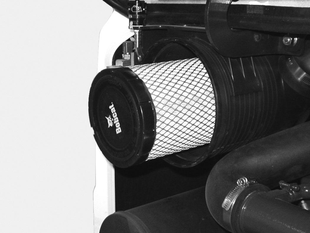
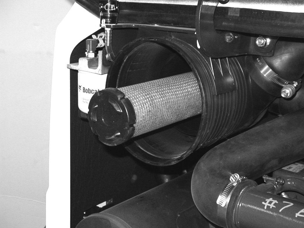
Pull the outer filter (Item 1) [Figure 297] from the air cleaner housing.
Check the housing for damage.
Clean the housing and the seal surface. DO NOT use compressed air.
Install a new filter.
Install the dust cup (Item 1) and engage the three fasteners (Item 2) [Figure 298]
Check the air intake hose and the air cleaner housing for damage. Make sure all connections are tight.
After the outer filter has been replaced, press the button (Item 1) [Figure 295] on the end of the condition indicator and start the engine. Run at full rpm, then reduce engine speed and stop the engine. If the red ring (Item 2) [Figure 295] shows in the condition indicator, replace the inner filter.
AIR CLEANER SERVICE (CONT’D)
Replacing Filter Elements (Cont’d)
Inner Filter
Only replace the inner filter under the following conditions:
•Replace the inner filter every third time the outer filter is replaced.
•After the outer filter has been replaced, press the button (Item 2) [Figure 295] on the end of the condition indicator. Start the engine. Run the engine at full rpm, then reduce engine speed. Stop the engine. If the red ring shows in the condition indicator, replace the inner filter.
Remove the dust cup, outer filter and inner filter (Item 1) [Figure 299]
NOTE: Make sure all sealing surfaces are free of dirt and debris.
Install the new inner filter.
Install the outer filter and the dust cup.
Press the button on the condition indicator to remove the red ring.
Close the tailgate.
Fuel System
Fuel Specifications
NOTE: Contact your local fuel supplier to receive recommendations for your region.
At a minimum, low sulfur diesel fuel must be used in this machine. Low sulfur is defined as 500 mg/kg (500 ppm) sulfur maximum.
Ultra low sulfur diesel fuel may also be used in this machine. Ultra low sulfur is defined as 15 mg/kg (15 ppm) sulfur maximum.
U.S. Standard (ASTM D975)
Use only clean, high quality diesel fuel, Grade Number 2-D or Grade Number 1-D.
The following is one suggested blending guideline that should prevent fuel gelling during cold temperatures:
Biodiesel Blend Fuel
Biodiesel blend fuel has unique qualities that should be considered before using in this machine:
•Cold weather conditions can lead to plugged fuel system components and hard starting.
•Biodiesel blend fuel is an excellent medium for microbial growth and contamination which can cause corrosion and plugging of fuel system components.
•Use of biodiesel blend fuel may result in premature failure of fuel system components, such as plugged fuel filters and deteriorated fuel lines.
•Shorter maintenance intervals may be required, such as cleaning the fuel system and replacing fuel filters and fuel lines.
Above -9°C (+15°F)100%0% Down to -21°C (-5°F)50%50% Below -21°C (-5°F)0%100%
NOTE:Biodiesel blend fuel may also be used in this machine. Biodiesel blend fuel must contain no more than five percent biodiesel mixed with ultra low sulfur petroleum based diesel. This biodiesel blend fuel is commonly marketed as B5 blended diesel fuel. B5 blended diesel fuel must meet ASTM specifications.
E.U. Standard (EN590)
Use only clean, high quality diesel fuel that meets the specifications listed below:
•Low sulfur diesel fuel defined as 500 mg/kg (500 ppm) sulfur maximum
•Diesel fuel with cetane number of 51.0 and above.
Clean, high quality diesel fuel that meets the EN590 specification may also be used.
NOTE:Biodiesel blend fuel may also be used in this machine. Biodiesel blend fuel must contain no more than seven percent biodiesel mixed with ultra low sulfur petroleum based diesel. This biodiesel blend fuel is commonly marketed as B7 blended diesel fuel. B7 blended diesel fuel must meet EN590 specifications.
•Using biodiesel blended fuels containing more than five percent biodiesel can affect engine life and cause deterioration of hoses, tubelines, injectors, injector pump and seals.
Apply the following guidelines if biodiesel blend fuel is used:
•Ensure the fuel tank is as full as possible at all times to prevent moisture from collecting in the fuel tank.
•Ensure that the fuel tank cap is securely tightened.
•Biodiesel blend fuel can damage painted surfaces, remove all spilled fuel from painted surfaces immediately.
•Drain all water from the fuel filter daily before operating the machine.
•Do not exceed engine oil change interval. Extended oil change intervals can cause engine damage.
•Before vehicle storage; drain the fuel tank, refill with 100% petroleum diesel fuel, add fuel stabilizer and run the engine for at least 30 minutes.
NOTE:Biodiesel blend fuel does not have long term stability and should not be stored for more than three months.
FUEL SYSTEM (CONT’D)
Filling The Fuel Tank
Warning
AVOID INJURY OR DEATH
Stop and cool the engine before adding fuel. NO SMOKING! Failure to obey warnings can cause an explosion or fire.
W-2063-0807
Warning
AVOID INJURY OR DEATH
Always clean up spilled fuel or oil. Keep heat, flames, sparks or lighted tobacco away from fuel and oil. Failure to use care around combustibles can cause explosion or fire.
W-2103-0508
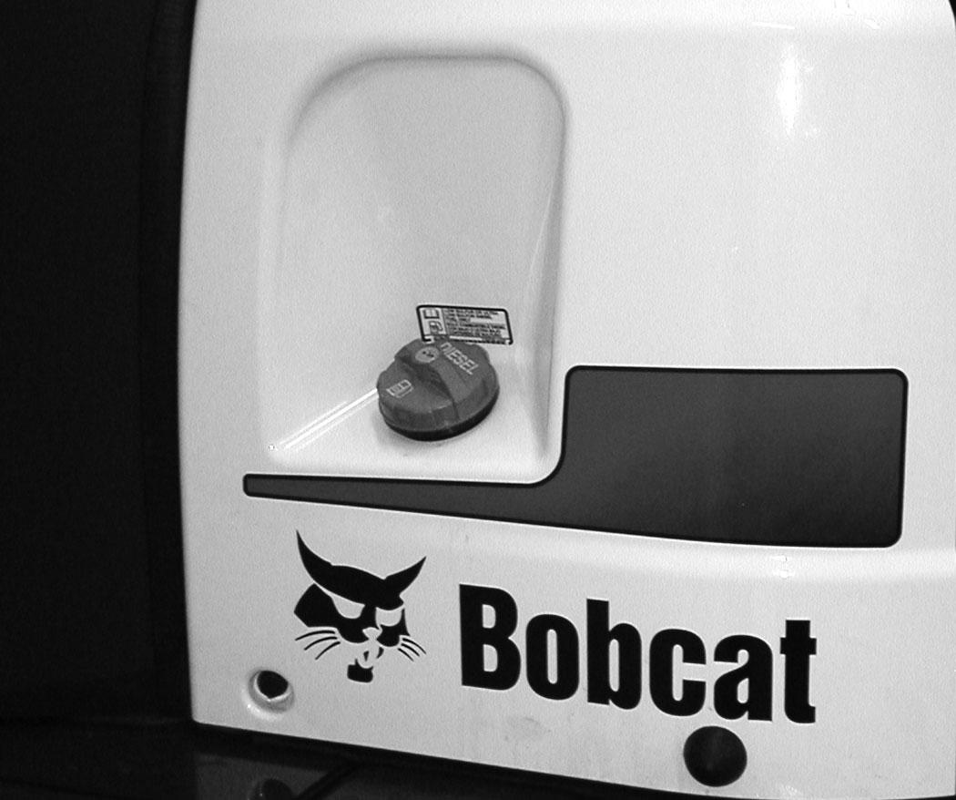
The fuel cap uses the start key to unlock the fuel cap.
Remove the fuel fill cap (Item 1) [Figure 300]
Use a clean, approved safety container to add fuel. Add fuel only in an area that has a free movement of air and no flames or sparks. NO SMOKING!
Install and tighten the fuel fill cap.
Clean up any spilled fuel.
See the SERVICE SCHEDULE for the service interval when to remove water from or replace the fuel filter. (See SERVICE SCHEDULE on Page 153.)
FUEL SYSTEM (CONT’D)
Fuel Filters
Removing Water
Open the tailgate. (See TAILGATE on Page 159.)
Draining The Fuel Tank
See the SERVICE SCHEDULE for the correct service interval. (See SERVICE SCHEDULE on Page 153.)
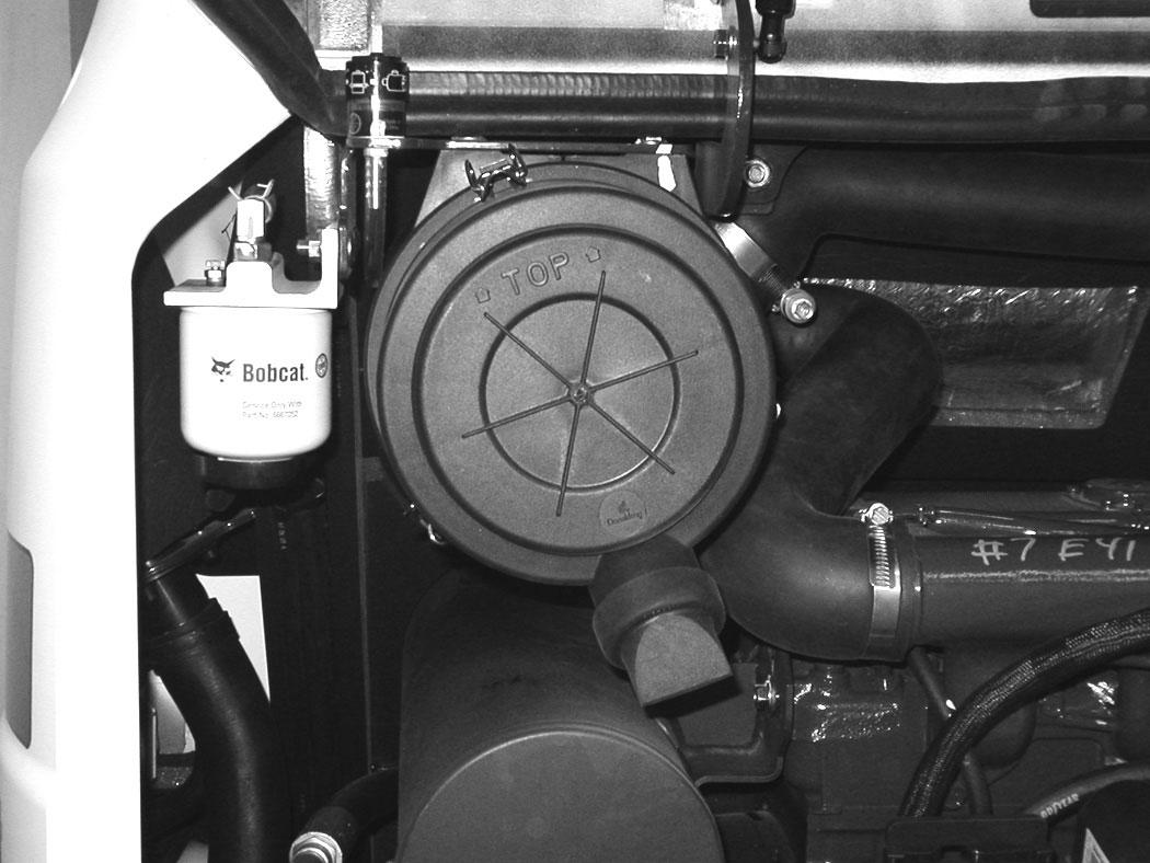
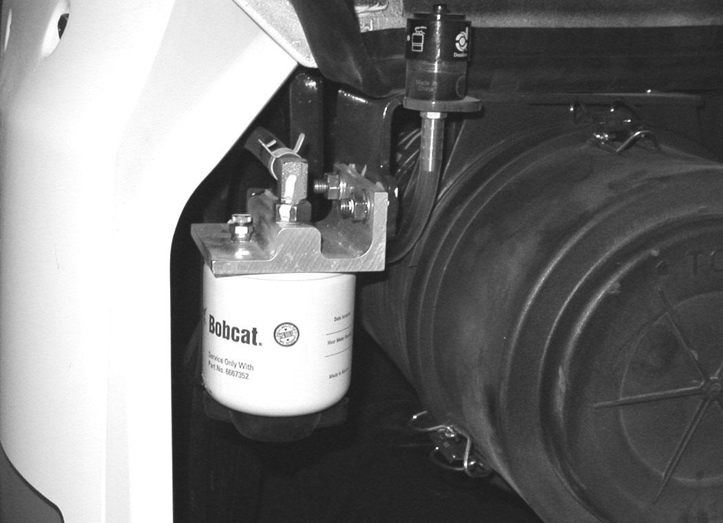
Loosen the drain (Item 1) [Figure 301] at the bottom of the filter to drain water from the filter into a container.
Clean up any spilled fuel.
Replacing Elements
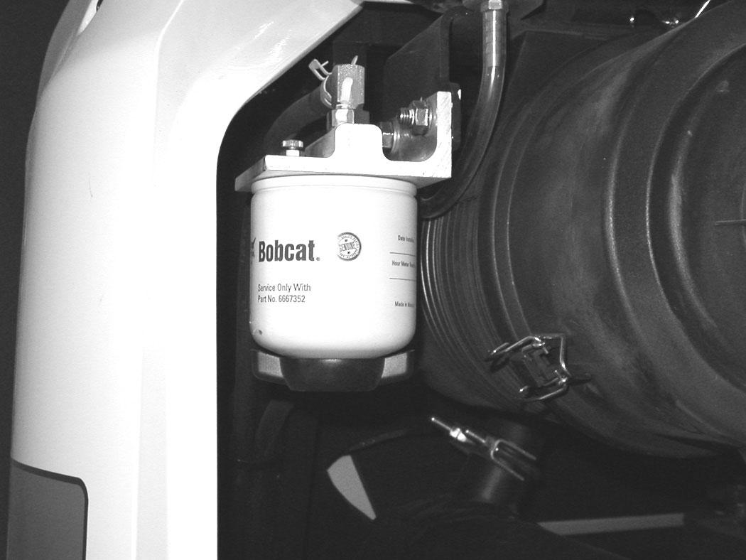
Remove the filter (Item 2) [Figure 301].
Clean the area around the filter housing. Put clean oil on the seal of the new filter. Install the fuel filter and hand tighten.
Remove the air from the fuel system. (See Removing Air From The Fuel System on Page 168.)
Warning
Avoid Injury Or Death
Diesel fuel or hydraulic fluid under pressure can penetrate skin or eyes, causing serious injury or death. Fluid leaks under pressure may not be visible. Use a piece of cardboard or wood to find leaks. Do not use your bare hand. Wear safety goggles. If fluid enters skin or eyes, get immediate medical attention from a physician familiar with this injury.
W-2072-0807
Remove the hose (Item 1) [Figure 302] from the fuel filter. Route the hose to a container.
Squeeze the hand pump (priming bulb) (Item 1) [Figure 303] to start the fuel siphoning from the fuel tank.
Drain the fuel into the container.
Reuse, recycle or dispose of fuel in an environmentally safe manner.
Reinstall the hose (Item 1) [Figure 302] after the fuel is removed from fuel tank.
FUEL SYSTEM (CONT’D)
Removing Air From The Fuel System
After replacing the fuel filter or when the fuel tank has run out of fuel, air must be removed from the fuel system before starting the engine.
Warning
Avoid Injury Or Death
Diesel fuel or hydraulic fluid under pressure can penetrate skin or eyes, causing serious injury or death. Fluid leaks under pressure may not be visible. Use a piece of cardboard or wood to find leaks. Do not use your bare hand. Wear safety goggles. If fluid enters skin or eyes, get immediate medical attention from a physician familiar with this injury.
Open the tailgate. (See TAILGATE on Page 159.)
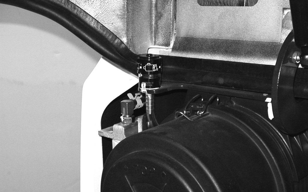
Open the fuel filter vent (Item 1) [Figure 304] and operate the hand pump (priming bulb) (Item 1) [Figure 305] until the fuel flows from the vent with no air bubbles.
Close the vent (Item 1) [Figure 304]
Clean up any spilled fuel.
Start the engine. It may be necessary to open the vent (Item 2) [Figure 305] (at the fuel injection pump) briefly until the engine runs smoothly.
Engine Lubrication System
Checking And Adding Engine Oil
Check the engine oil after every 8 - 10 hours of operation and before starting the engine. (See SERVICE SCHEDULE on Page 153.)
Figure 306
Open the tailgate. (See TAILGATE on Page 159.)
Remove the dipstick (Item 1) [Figure 306]
Keep the oil level between the marks on the dipstick.
Use a good quality motor oil that meets the correct API Service Classification.
Engine Oil Chart
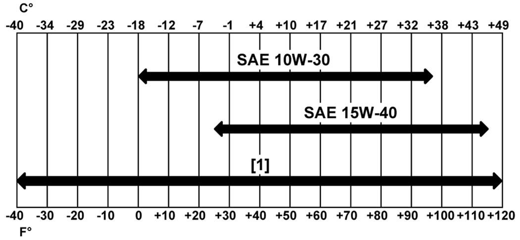
Figure 307
Engine Oil
RECOMMENDED SAE VISCOSITY NUMBER (LUBRICATION OILS FOR DIESEL ENGINE CRANKCASE)
TEMPERATURE RANGE ANTICIPATED BEFORE NEXT OIL CHANGE (DIESEL ENGINES MUST USE API CLASSIFICATION CJ-4 OR BETTER, OR ACEA E9 OR BETTER)
[1] Bobcat Synthetic Oil – 5W-40
Bobcat engine oils are recommended for use in this machine. If Bobcat engine oil is not available, use a good quality engine oil that meets API Service Classification of CJ-4 or better, or ACEA E9 or better [Figure 307]
Warning
Avoid Injury Or Death
Always clean up spilled fuel or oil. Keep heat, flames, sparks or lighted tobacco away from fuel and oil. Failure to use care around combustibles can cause explosion or fire.
W-2103-0508
ENGINE LUBRICATION SYSTEM (CONT’D)
Removing And Replacing Oil And Filter
See the SERVICE SCHEDULE for the service interval for replacing the engine oil and filter. (See SERVICE SCHEDULE on Page 153.)
Run the engine until it is at operating temperature. Stop the engine.
Open the tailgate. (See TAILGATE on Page 159.)
Figure 310
If equipped with the optional air deflector, remove the four bolts and the air deflector to access the drain hose (Item 1) [Figure 308].
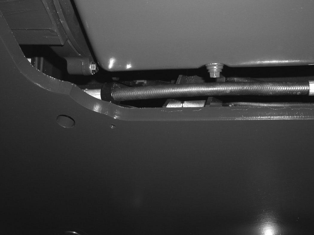
Remove the drain hose (Item 1) from the storage clamp (Item 2) [Figure 308]
309
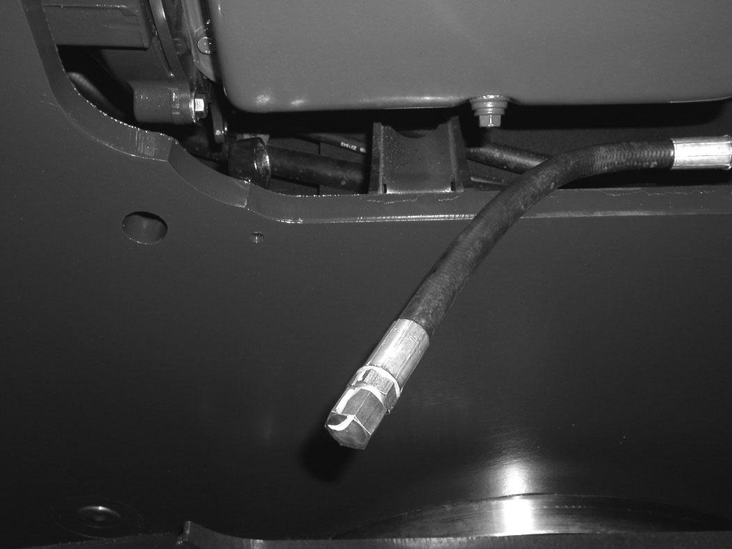
Place a container under the excavator. Remove the drain plug (Item 1) [Figure 309] from the drain hose.
Recycle or dispose of used oil in an environmentally safe manner.
Remove the oil filter (Item 1) [Figure 310] and clean the filter housing surface.
Use a genuine Bobcat replacement filter. Put clean oil on the filter gasket. Install the filter and hand tighten.
Install and tighten the drain plug (Item 1) [Figure 309]
Put the drain hose (Item 1) back into the storage clamp (Item 2) [Figure 308]
311
Remove the fill cap (Item 1) [Figure 311].
Put oil in the engine. (See ENGINE LUBRICATION SYSTEM on Page 169.) and (See Capacities on Page 232.)
Install the fill cap (Item 1) [Figure 311]
Start the engine and let it run for several minutes.
Stop the engine. Check for leaks at the oil drain plug and the oil filter. Check the oil level.
Add oil as needed if it is not at the top mark on the dipstick.
Engine Cooling System
Check the cooling system every day to prevent over-heating, loss of performance or engine damage. (See SERVICE SCHEDULE on Page 153.)
Cleaning
Open the right side cover. (See RIGHT SIDE COVER on Page 160.)
NOTE:Allow the cooling system and engine to cool before servicing or cleaning the cooling system.
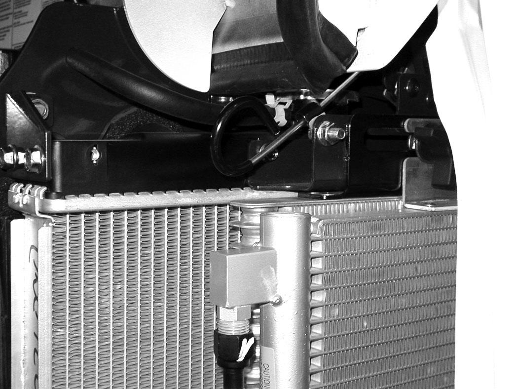
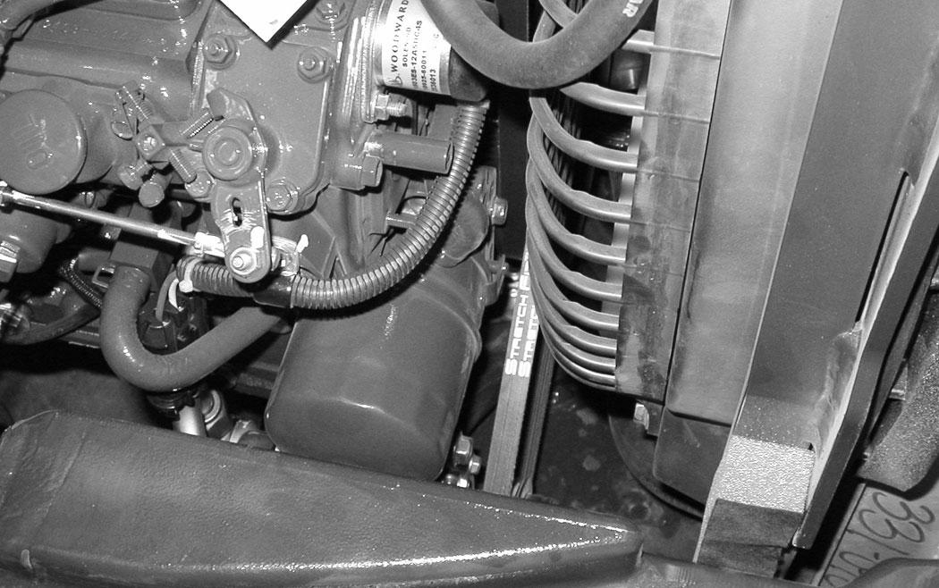
Loosen the knob (Item 1) [Figure 312]. Slide the knob towards the rear of the machine.
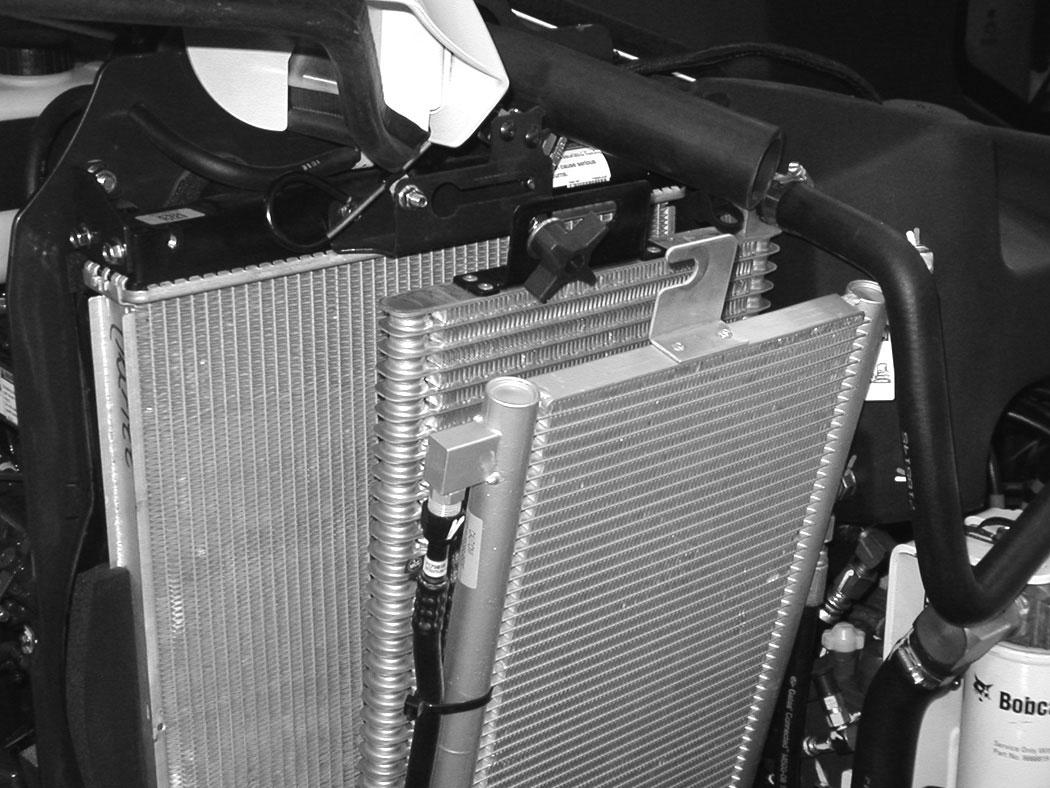
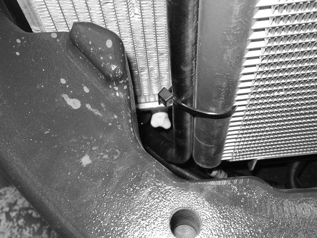
Use air pressure or water pressure to clean the radiator (Item 1), oil cooler (Item 2) and condenser (Item 3) [Figure 314] (if equipped). Be careful not to damage fins when cleaning.
Position the knob (Item 1) so it fits into the radiator mount (Item 3) and the condenser mount (Item 2) [Figure 313] (if equipped).
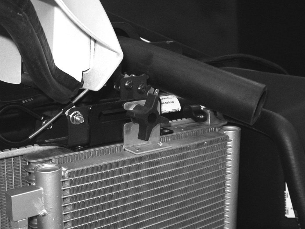
Slide the knob (Item 1) [Figure 312] toward the front of the machine until it is fully seated in the slots of the mounting brackets. Tighten the knob (Item 1) [Figure 312]. Be careful not to damage fins.
Slide the knob (Item 1) out of the condenser mount (Item 2) (if equipped) and the radiator mounting bracket (Item 3) [Figure 313]. Be careful not to damage fins.
ENGINE COOLING SYSTEM (CONT’D)
Checking Level
Warning
AVOID BURNS
Do not remove radiator cap when the engine is hot. You can be seriously burned.
W-2070-1203
Warning
AVOID INJURY OR DEATH
Wear safety glasses to prevent eye injury when any of the following conditions exist:
•When fluids are under pressure.
•Flying debris or loose material is present.
•Engine is running.
•Tools are being used.
W-2019-0907
Open the tailgate. (See TAILGATE on Page 159.)
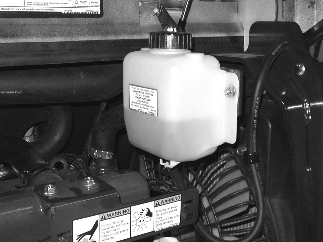
Figure 315
Important
AVOID ENGINE DAMAGE
Always use the correct ratio of water to antifreeze.
Too much antifreeze reduces cooling system efficiency and may cause serious premature engine damage.
Too little antifreeze reduces the additives which protect the internal engine components; reduces the boiling point and freeze protection of the system.
Always add a premixed solution. Adding full strength concentrated coolant can cause serious premature engine damage.
I-2124-0497
Check the coolant level in the coolant recovery tank (Item 1) [Figure 315].
The coolant level must be between the MIN and MAX marks on the coolant recovery tank when the engine is cold.
NOTE: The cooling system is factory filled with propylene glycol (purple color). DO NOT mix propylene glycol with ethylene glycol.
ENGINE COOLING SYSTEM (CONT’D)
Removing And Replacing Coolant
See the SERVICE SCHEDULE for correct service intervals. (See SERVICE SCHEDULE on Page 153.)
Stop the engine. Open the tailgate. (See TAILGATE on Page 159.)
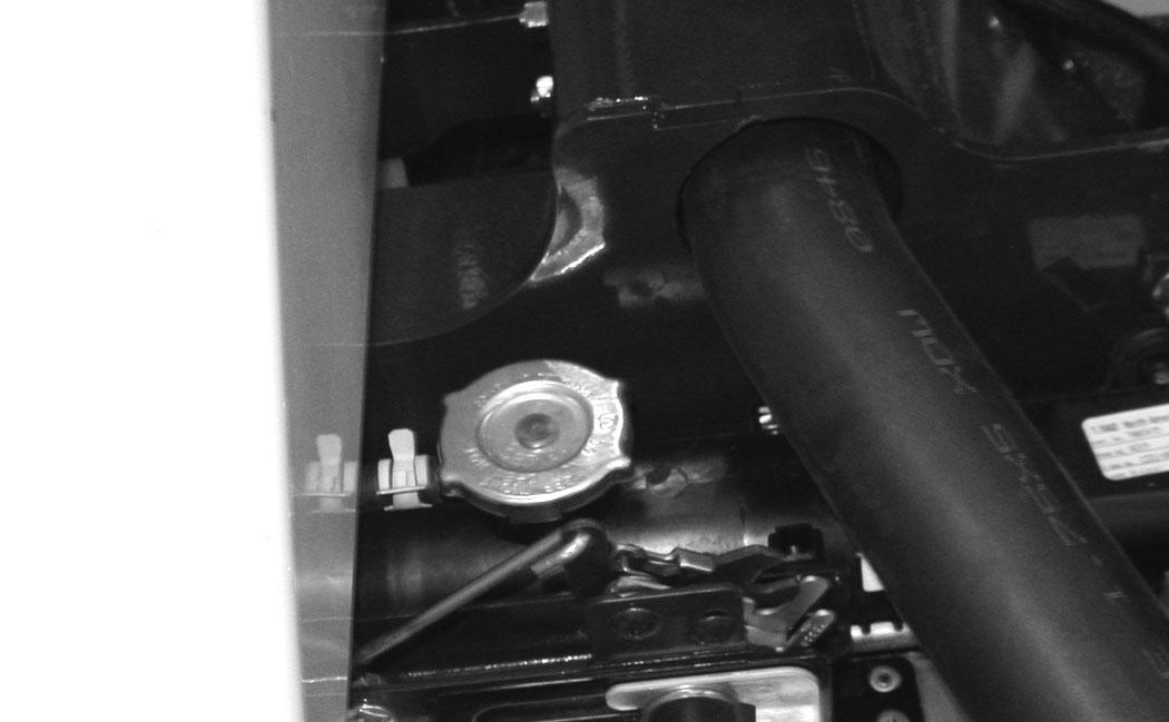
Warning
AVOID BURNS
Do not remove radiator cap when the engine is hot. You can be seriously burned.
When the engine is cool, loosen and remove the radiator cap (Item 1) [Figure 316].
After all the coolant is removed, close both drain valves. Recycle or dispose of the used coolant in an environmentally safe manner.
Mix the coolant in a separate container. (See ENGINE COOLING SYSTEM on Page 171.) and (See Capacities on Page 232.)
NOTE: The cooling system is factory filled with propylene glycol (purple color). DO NOT mix propylene glycol with ethylene glycol.
The correct mixture of coolant to provide a -37°C (-34°F) freeze protection is 5 L propylene glycol mixed with 4,4 L of water OR 1 U.S. gal propylene glycol mixed with 3.5 qt of water.
Add premixed coolant; 47% water and 53% propylene glycol to the recovery tank if the coolant level is low.
Use a refractometer to check the condition of propylene glycol in your cooling system.
Add premixed coolant until the level is correct.
Run the engine until it is at operating temperature. Stop the engine. Check the coolant level and add as needed. Be sure the radiator cap is tight.
Add coolant to the recovery tank as needed.
Close the tailgate.