3 minute read
OVERLOAD WARNING DEVICE


Description
NOTE:The excavator must be equipped with the optional boom load holding valve to installed for the overload warning device.
The overload warning device (if equipped) senses hydraulic pressure in the boom lift circuit. When the hydraulic pressure in the boom lift circuit reaches a predetermined pressure setting, a buzzer will sound that indicates an overload condition.
If the buzzer sounds, immediately move the arm closer to the excavator and lower the boom. Reduce the size of the load before attempting to re-lift the load.
Warning
AVOID INJURY OR DEATH
Do Not work or stand under raised work equipment or attachment.
W-2793-0409
Operation
Figure73
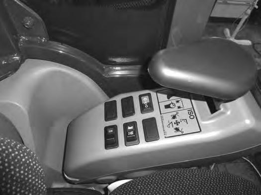
Press the switch (Item 1) to the left. This will activate the optional pressure switch (Item 2) [Figure73] in the boom load hold valve.
Press the switch (Item 1) [Figure73] to the right to shut the overload warning feature OFF.

Daily Inspection
Daily Inspection And Maintenance
Figure74
Warning
Operator must have instructions before operating the machine. Untrained operators can cause injury or death.
W-2001-0502
Fluids such as engine oil, hydraulic fluid, coolants, etc. must be disposed of in an environmentally safe manner. Some regulations require that certain spills and leaks on the ground must be cleaned in a specific manner. See local state and federal regulations for correct disposal.
Important
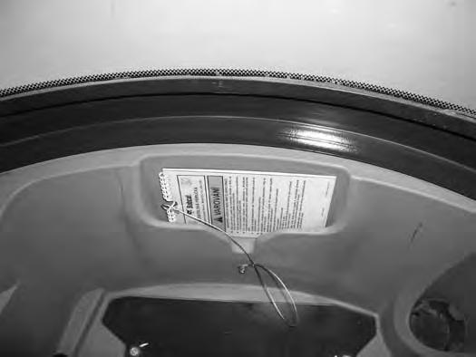
Maintenance work must be done at regular intervals. Failure to do so will result in excessive wear and early failures. The service schedule is a guide for correct maintenance of the Bobcat excavator. The decal (Item 1) [Figure74] is located on the inside of the tailgate. (See SERVICE SCHEDULE on Page 103.)
Check the following items before each day of operation:
•Operator Canopy or Cab (ROPS / TOPS) and mounting hardware.
•Seat belt and mounting hardware. Replace seat belt if damaged.
•Check for damaged decals, replace as needed.
•Check control console lockout.
•Check Attachment Mounting System (if equipped) for damage or loose parts.
•Air cleaner and intake hoses / clamps.
•Engine oil level and engine for leaks.
•Drain water from fuel filter.
•Engine coolant level and engine for leaks.
•Check engine area for flammable materials.

•Check hydraulic fluid level and system for leaks.
•Check indicator lights for correct operation.
•Grease all pivot points.
•Check cylinder and attachment pivot points.
•Check the track tension.
•Repair broken and loose parts.
•Clean cab heater filter (if equipped).
•Check front horn and motion alarm (if equipped) for proper function.
Pressure Washing Decals
•Never direct the stream at a low angle toward the decal that could damage the decal causing it to peel from the surface.
•Direct the stream at a 90 degree angle and at least 300 mm (12 in) from the decal. Wash from the center of the decal toward the edges.
I-2226-0910
Important
This machine is factory equipped with a U.S.D.A. Forestry Service approved spark arrester exhaust system.
The spark arrester muffler, if equipped, must be cleaned to keep it in working condition. The spark arrester muffler must be serviced by dumping the spark chamber every 100 hours of operation.
On some models, the turbocharger functions as the spark arrester and must operate correctly for proper spark arrester function.
If this machine is operated on flammable forest, brush, or grass covered land, it must be equipped with a spark arrester attached to the exhaust system and maintained in working order. Failure to do so will be in violation of California State Law, Section 4442. PRC. Refer to local laws and regulations for spark arrester requirements.
I-2284-0111
PRE-STARTING PROCEDURE
Operation & Maintenance Manual And Operator’s Handbook Locations

Entering The Excavator
Warning
AVOID INJURY OR DEATH
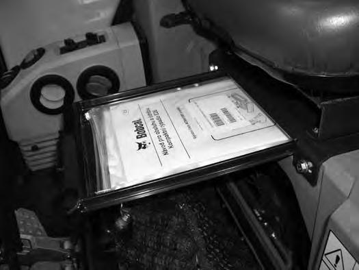
Read and understand the Operation & Maintenance Manual (Item 1) [Figure75] (located inside the storage box below the operator’s seat) and the Operator’s Handbook (Item 1) [Figure76] located behind the operator’s seat before operating.
Instructions are necessary before operating or servicing machine. Read and understand the Operation & Maintenance Manual, Operator’s Handbook and signs (decals) on machine. Follow warnings and instructions in the manuals when making repairs, adjustments or servicing. Check for correct function after adjustments, repairs or service. Untrained operators and failure to follow instructions can cause injury or death.
W-2003-0807
PRE-STARTING PROCEDURE (CONT’D)
Seat Adjustment
Basic Seat (If Equipped)
Figure78
The basic seat has no adjustments [Figure78]
Standard Seat (If Equipped)
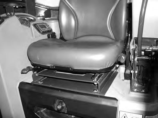
Figure79
Release the seat lever (Item 1) [Figure79] to adjust the seat forward or back.
Release the seat lever (Item 2) [Figure79] to adjust the position of the back cushion.

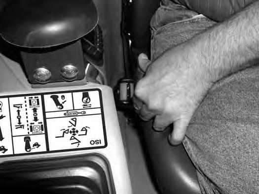
Suspension Seat (If Equipped)

Figure80
Release the seat lever (Item 1) [Figure80] to adjust the seat forward or back.
Turn the handle (Item 2) [Figure80] to change the adjustment for operator weight.
Release the lever (Item 3) [Figure80] to change the incline of the seat back.
Seat Belt
Figure81
Fasten the seat belt [Figure81].