31 minute read
FEATURES, ACCESSORIES AND ATTACHMENTS (CONT’D)


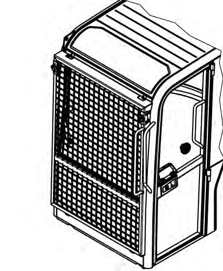
Falling-Object Guards (FOGS)
Figure5
Overhead Guard
Available for special applications that require protection from smaller objects that can fall on the canopy / cab or restrict material from entering cab openings [Figure5] and [Figure6].
Excavator equipped with a cab (canopy excavators are equipped with the overhead guard as standard equipment) must have the overhead guard [Figure5] installed to meet the top guard requirements in ISO 10262.
See your Bobcat Dealer for more information.
NOTE:The Falling-Object Guard is factory installed on the canopy.
Special Applications Kit
Figure6 The excavator must have the special applications kit [Figure6] installed to meet the front guard requirements in ISO 10262 - level 1.
Special Application Kit
Kit includes an upper and lower screen guard.
See your Bobcat Dealer for more information.
Special Applications Kit Inspection And Maintenance
The Special Applications Kit must be regularly inspected and maintained. Inspect the screen for damage. Replace parts as necessary.

SAFETY INSTRUCTIONS Before Operation
Carefully follow the operating and maintenance instructions in this manual.
The Bobcat excavator is highly maneuverable and compact. It is rugged and useful under a wide variety of conditions. This presents an operator with hazards associated with off highway, rough terrain applications, common with Bobcat excavator usage.
The Bobcat excavator has an internal combustion engine with resultant heat and exhaust. All exhaust gases can kill or cause illness so use the excavator with adequate ventilation.
The dealer explains the capabilities and restrictions of the Bobcat excavator and attachment for each application. The dealer demonstrates the safe operation according to Bobcat instructional materials, which are also available to operators. The dealer can also identify unsafe modifications or use of unapproved attachments. The attachments and buckets are designed for a Rated Lift Capacity. They are designed for secure fastening to the Bobcat excavator. The user must check with the dealer, or Bobcat literature, to determine safe loads of materials of specified densities for the machineattachment combination.
The following publications and training materials provide information on the safe use and maintenance of the Bobcat machine and attachments:
•The Delivery Report is used to assure that complete instructions have been given to the new owner and that the machine and attachment is in safe operating condition.
•The Operation & Maintenance Manual delivered with the machine or attachment gives operating information as well as routine maintenance and service procedures. It is a part of the machine and can be stored in a container provided on the machine. Replacement Operation & Maintenance Manuals can be ordered from your Bobcat dealer.
•Machine signs (decals) instruct on the safe operation and care of your Bobcat machine or attachment. The signs and their locations are shown in the Operation & Maintenance Manual. Replacement signs are available from your Bobcat dealer.

•An Operator’s Handbook is fastened to the operator cab of the excavator. It’s brief instructions are convenient to the operator. The handbook is available from your dealer in an English edition or one of many other languages. See your Bobcat dealer for more information on translated versions.
•The AEM Safety Manual delivered with the machine gives general safety information.
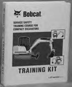
•The Compact Excavator Operating Training Course is available through your Bobcat dealer. This course is intended to provide rules and practices of correct operation of the Bobcat excavator. The course is available in English and Spanish versions.
•Service Safety Training Courses are available from your Bobcat dealer. They provide information for safe and correct service procedures.
•See the PUBLICATIONS AND TRAINING RESOURCES Page in this manual or your Bobcat dealer for Service and Parts Manuals, printed materials, videos, or training courses available. Also check the Bobcat web sites www.training.bobcat.com or www.bobcat.com
The dealer and owner / operator review the recommended uses of the product when delivered. If the owner / operator will be using the machine for a different application(s) he or she must ask the dealer for recommendations on the new use.
SAFETY INSTRUCTIONS (CONT’D)
Safe Operation Is The Operator’s Responsibility
Safety Alert Symbol
This symbol with a warning statement means: “Warning, be alert! Your safety is involved!” Carefully read the message that follows.
Warning
Operator must have instructions before operating the machine. Untrained operators can cause injury or death.
W-2001-0502
Important
This notice identifies procedures which must be followed to avoid damage to the machine.
I-2019-0284
Danger
The signal word DANGER on the machine and in the manuals indicates a hazardous situation which, if not avoided, will result in death or serious injury.
D-1002-1107
Warning
The signal word WARNING on the machine and in the manuals indicates a potentially hazardous situation which, if not avoided, could result in death or serious injury.
W-2044-1107
The Bobcat excavator and attachment must be in good operating condition before use.
Check all of the items on the Bobcat Service Schedule Decal under the 8-10 hour column or as shown in the Operation & Maintenance Manual.
Safe Operation Needs A Qualified Operator
For an operator to be qualified, he or she must not use drugs or alcoholic drinks which impair alertness or coordination while working. An operator who is taking prescription drugs must get medical advice to determine if he or she can safely operate a machine.
A Qualified Operator Must Do The Following:
Understand the Written Instructions, Rules and Regulations
•The written instructions from Bobcat Company include the Delivery Report, Operation & Maintenance Manual, Operator’s Handbook, Safety Manual and machine signs (decals).
•Check the rules and regulations at your location. The rules may include an employer’s work safety requirements. Regulations may apply to local driving requirements or use of a Slow Moving Vehicle (SMV) emblem. Regulations may identify a hazard such as a utility line.
Have Training with Actual Operation
•Operator training must consist of a demonstration and verbal instruction. This training is given by your Bobcat dealer before the product is delivered.
•The new operator must start in an area without bystanders and use all the controls until he or she can operate the machine and attachment safely under all conditions of the work area. Always fasten seat belt before operating.
•Operator Training Courses are available from your Bobcat dealer in English and Spanish. They provide information for safe and efficient equipment operation. Safety videos are also available.
•Service Safety Training Courses are available from your Bobcat dealer. They provide information for safe and correct service procedures.
Know the Work Conditions
•Know the weight of the materials being handled. Avoid exceeding the Rated Lift Capacity of the machine. Material which is very dense will be heavier than the same volume of less dense material. Reduce the size of load if handling dense material.
•The operator must know any prohibited uses or work areas, for example, he or she needs to know about excessive slopes.
•Know the location of any underground lines. Call local utilities or the TOLL FREE phone number found in the Before Operation section of this manual.
•Wear tight fitting clothing. Always wear safety glasses when doing maintenance or service. Safety glasses, respiratory equipment, hearing protection or Special Applications Kits are required for some work. See your Bobcat dealer about Bobcat safety equipment for your model.
SI EXC-0913
SAFETY INSTRUCTIONS (CONT’D)
Avoid Silica Dust
Cutting or drilling concrete containing sand or rock containing quartz may result in exposure to silica dust. Do not exceed Permissible Exposure Limits (PEL) to silica dust as determined by OSHA or other job site Rules and Regulations. Use a respirator, water spray or other means to control dust. Silica dust can cause lung disease and is known to the state of California to cause cancer.
Fire Prevention
Maintenance
The machine and some attachments have components that are at high temperatures under normal operating conditions. The primary source of high temperatures is the engine and exhaust system. The electrical system, if damaged or incorrectly maintained, can be a source of arcs or sparks.
Flammable debris (leaves, straw, etc.) must be removed regularly. If flammable debris is allowed to accumulate, it can cause a fire hazard. Clean often to avoid this accumulation. Flammable debris in the engine compartment is a potential fire hazard.
The operator’s area, engine compartment and engine cooling system must be inspected every day and cleaned if necessary to prevent fire hazards and overheating.
All fuels, most lubricants and some coolant mixtures are flammable. Flammable fluids that are leaking or spilled onto hot surfaces or onto electrical components can cause a fire.
Operation
Do not use the machine where exhaust, arcs, sparks or hot components can contact flammable material, explosive dust or gases.
Electrical
Check all electrical wiring and connections for damage. Keep the battery terminals clean and tight. Repair or replace any damaged part or wires that are loose or frayed.
Battery gas can explode and cause serious injury. Use the procedure in the Operation & Maintenance Manual for connecting the battery and for jump starting. Do not jump start or charge a frozen or damaged battery. Keep any open flames or sparks away from batteries. Do not smoke in battery charging area. SI EXC-0913
FIRE PREVENTION (CONT’D)
Hydraulic System
Check hydraulic tubes, hoses and fittings for damage and leakage. Never use open flame or bare skin to check for leaks. Hydraulic tubes and hoses must be properly routed and have adequate support and secure clamps. Tighten or replace any parts that show leakage.
Always clean fluid spills. Do not use gasoline or diesel fuel for cleaning parts. Use commercial nonflammable solvents.
Fueling
Stop the engine and let it cool before adding fuel. No smoking! Do not refuel a machine near open flames or sparks. Fill the fuel tank outdoors.
Ultra Low Sulfur Diesel (ULSD) poses a greater static ignition hazard than earlier diesel formulations with higher Sulfur content. Avoid death or serious injury from fire or explosion. Consult with your fuel or fuel system supplier to ensure the delivery system is in compliance with fueling standards for proper grounding and bonding practices.
Starting
Do not use ether or starting fluids on any engine that has glow plugs or air intake heater. These starting aids can cause explosion and injure you or bystanders.
Use the procedure in the Operation & Maintenance Manual for connecting the battery and for jump starting.
Spark Arrester Exhaust System
The spark arrester exhaust system is designed to control the emission of hot particles from the engine and exhaust system, but the muffler and the exhaust gases are still hot.
Check the spark arrester exhaust system regularly to make sure it is maintained and working properly. Use the procedure in the Operation & Maintenance Manual for cleaning the spark arrester muffler (if equipped).
Welding And Grinding
Always clean the machine and attachment, disconnect the battery, and disconnect the wiring from the Bobcat controllers before welding. Cover rubber hoses, battery and all other flammable parts. Keep a fire extinguisher near the machine when welding.
Have good ventilation when grinding or welding painted parts. Wear dust mask when grinding painted parts. Toxic dust or gas can be produced.
Dust generated from repairing nonmetallic parts such as hoods, fenders or covers can be flammable or explosive. Repair such components in a well ventilated area away from open flames or sparks.
Fire Extinguishers
Know where fire extinguishers and first aid kits are located and how to use them. Inspect the fire extinguisher and service the fire extinguisher regularly. Obey the recommendations on the instructions plate.
Publications And Training Resources
The following publications are also available for your Bobcat excavator. You can order them from your Bobcat dealer.
For the latest information on Bobcat products and the Bobcat Company, visit our web site at www.bobcat.com; you can also order Operator and Service Training materials online through www.bobcatstore.com

OPERATION & MAINTENANCE MANUAL

7256913enUS
- Complete instructions on the correct operation and the routine maintenance of the Bobcat excavator.
SERVICE MANUAL
7255013enUS
- Complete maintenance instructions for your Bobcat excavator.
SAFETY MANUAL
6901951
- Provide basic safety procedures and warnings for your Bobcat excavator.
OPERATOR’S HANDBOOK
7255006enUS
Gives basic operation instructions and safety warnings
COMPACT EXCAVATOR OPERATOR TRAINING COURSE
6903186
Introduces operator to step-by-step basics of compact excavator operation. Also available in Spanish P/N 6903228

EXCAVATOR SERVICE SAFETY COURSE
6900916
Introduces Service Technicians to step-by-step basics of proper and safe excavator maintenance and servicing procedures
OPERATOR SAFETY DVD
6904762
Provides basic safety instructions contained in all Bobcat Safety Videos in both English and Spanish. EXCAVATOR SAFETY VIDEO
(Mobile device with quick response code application required)
Scan the code above to watch the excavator safety video or view at www.training.bobcat.com
MACHINE SIGNS (DECALS)
Follow the instructions on all the Machine Signs (Decals) that are on the excavator. Replace any damaged machine signs and be sure they are in the correct locations. Machine signs are available from your Bobcat excavator dealer.
MACHINE SIGNS (DECALS) (CONT’D)
Follow the instructions on all the Machine Signs (Decals) that are on the excavator. Replace any damaged machine signs and be sure they are in the correct locations. Machine signs are available from your Bobcat excavator dealer.
MACHINE SIGNS (DECALS) (CONT’D)
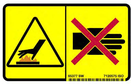
No-Text Safety Signs
Safety signs are used to alert the equipment operator or maintenance person to hazards that may be encountered in the use and maintenance of the equipment. The location and description of the safety signs are detailed in this section. Please become familiarized with all safety signs installed on the excavator.
Vertical Configuration
NOTE: See the numbered MACHINE SIGNS (DECALS) on Page 20 and Machine Signs (Decals) (Cont’d) on Page 21 for the machine location of each corresponding numbered no-text decals as shown below.
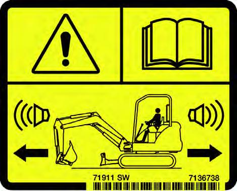
1.Motion Alarm (7136738)
This safety sign is located on the right window (cab models), rear crossmember (canopy models).

HAZARD PANEL
AVOIDANCE PANEL
Horizontal Configuration
Warning
This machine is equipped with a motion alarm. ALARM MUST SOUND! when operating forward or backward.
Failure to maintain a clear view in the direction of travel could result in serious injury or death.
HAZARD PANEL AVOIDANCE PANEL
The format consists of the hazard panel(s) and the avoidance panel(s):
Hazard panels depict a potential hazard enclosed in a safety alert triangle.

Avoidance panels depict actions required to avoid the hazards.
A safety sign may contain more than one hazard panel and more than one avoidance panel.
The operator is responsible for the safe operation of this machine.
W-2786-0309
MACHINE SIGNS (DECALS) (CONT’D)
No-Text Safety Signs (Cont’d)
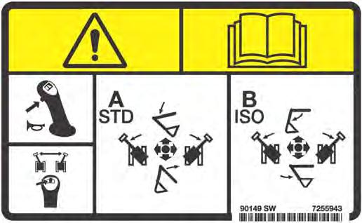
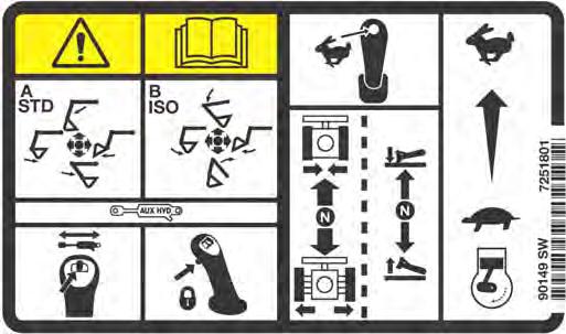
2.Control Pattern / Joystick (7251803, 7251801, 7255943)
These safety signs are located on the left console by the seat and on both consoles by the joysticks.
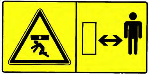

3.Crush Hazard (6713507)
This safety sign is located on both sides of the boom.
Warning
Know the control pattern before operating. W-2989-0714
Warning
Keep away from the operating machine to avoid serious injury or death.
W-2520-0106
4.Thrown Or Flying Objects (7168039)
This safety sign is located on the outside of both track frame.
Warning
High pressure grease can cause serious injury. Do not loosen grease fitting. Do not loosen bleed fitting more than 1 - 1/2 turns.
Read and understand the Operation & Maintenance Manual for more information.
W-2516-0110
MACHINE SIGNS (DECALS) (CONT’D)
No-Text Safety Signs (Cont’d)
5.Transporting And Lifting (7178215)
This safety sign is located on the front of the cab.
Warning
Improper loading, transporting and lifting procedures can cause serious injury or death. Read and understand the Operation & Maintenance Manual prior to transporting or lifting the machine.
W-2517-0110
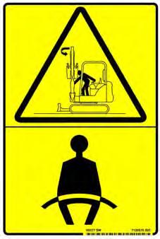
6.Transporting And Lifting (7120578)
This safety sign is located on the front of the cab.
Warning
•Keep out of swing area.
•Keep bystanders away.
•Operate the excavator from the operator’s position only.
W-2990-0714
7.General Hazard (7148158)
This safety sign is located inside the operator’s area on the left console.
Warning
Failure to obey warning signs and instructions can cause serious injury or death. Never use excavator without instructions. Read and understand the Operation & Maintenance Manual and Handbook.
Keep away from dropoffs, steep areas or banks that could break away.
Explosion or electrocution can occur if machine contacts utility lines or pipes. Check for overhead or underground lines before operating.
Keep bystanders away. No riders. Check location of blade for direction of travel before moving steering controls.
Failure to operate machine from the operator’s position can cause serious injury or death.
To Leave Excavator:
1. Lower attachment and blade to ground.
2. Stop engine and remove the key (if equipped).
3. Raise control console.
W-2518-0110
MACHINE SIGNS (DECALS) (CONT’D)
No-Text Safety Signs (Cont’d)
8.Lift Capacity (7255479, 7255480)
This safety sign is located on the right window (cab models) or on the rear crossmember (canopy models).
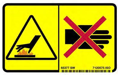

9.Rotating Fan and Hot Surfaces (7120579, 7185935)
This safety sign is located inside the engine compartment.
Warning
Overload can tip the excavator and cause serious injury or death.
•Do not lift or hold any load that exceeds these ratings at their specific load radii and height.
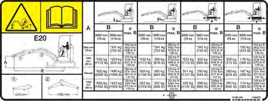
•Total rated load is shown. The weight of all lifting devices must be deducted to determine the net load that can be lifted.
Read and understand the Operation & Maintenance Manual for more information.
W-2519-0110
Warning
Rotating fan blade can cause serious injury or death. Keep away from fan and moving parts. Do not operate with guard removed.
Hot surfaces can cause injury. Do not touch. Allow to cool before servicing.
W-2521-0106
MACHINE SIGNS (DECALS) (CONT’D)
No-Text Safety Signs (Cont’d)
10.Hot Surfaces (7185935)
This safety sign is located in the right cover on the radiator.
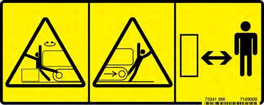
11.Stay Away (7169009)
This safety sign is located on both upper rear corners of the upperstructure.
Warning
AVOID BURNS
Do not remove radiator cap when the engine is hot. You can be seriously burned.
W-2070-1203
Warning
AVOID INJURY OR DEATH
•Keep out of swing area or travel path.
•Always look in the direction of travel.
•Make sure swing area is clear of bystanders and objects.
W-NEW-1108
MACHINE SIGNS (DECALS) (CONT’D)

No-Text Safety Signs (Cont’d)
12.High Pressure, Battery, Rotating Fan, Exhaust Gases and Service Schedule (7252176)
This safety sign is located inside the tailgate.
Warning
Leaking fluids under pressure can enter the skin and cause serious injury or death. Immediate medical attention is required. Wear goggles. Use cardboard to check for leaks.
Battery makes flammable and explosive gas. Keep arcs, sparks, flames and lighted tobacco away. Keep away from electrical contacts
Rotating fan can cause serious injury. Keep away from fan and moving parts. Do not operate with guard removed.
All exhaust gases can kill. Always ventilate. Read and understand the Operation & Maintenance Manual for more information.
W-2522-0110
Instruments And Consoles
Cab Interior Light

Interior light is equipped on excavators with a cab.
1 Left Joystick(See HYDRAULIC CONTROLS on Page 51.)
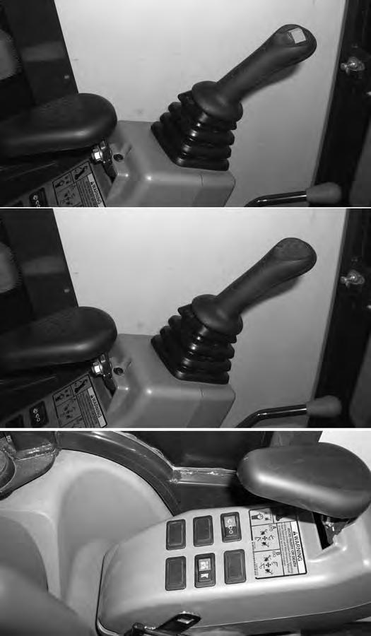
2 HornPress the switch on the left joystick to sound horn.
3 Boom Swing Switch (If Equipped)
Press the switch to the right (Item 1) to turn the light ON. Press the switch to the left (Item 2) [Figure7] to turn the light
4 Wiper / Washer Switch (If Equipped)
Move the switch to the left to swing the boom to the left. Move the switch to the right to swing the boom to the right. NOTE: For machine not equipped with switch (Item 3) in the left joystick, (See BOOM SWING on Page 59.)
Press the switch to the left to turn wiper ON. Press and hold switch to the left to activate window washer. Press the switch to the right to turn wiper OFF.
5 Not Used- - -
6 Beacon / Strobe Light (If Equipped)
7 Overload Warning Device Switch (If Equipped)
8 Blade / Track RetractionExpansion Switch
Press switch to the left to turn ON the beacon / Strobe light. Press the switch to the right to turn OFF.
Press the switch to the left to turn the overload warning device ON. Press to the right to turn OFF. (See OVERLOAD WARNING DEVICE on Page 64.)
Press the switch to the left to expand / retract the tracks. Press the switch to the right to raise and lower the boom. (See TRACK EXPANSION in this manual.)
9 Not Used- - -
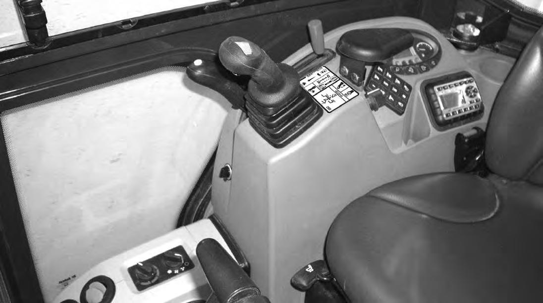
INSTRUMENTS AND CONSOLES (CONT’D)
Right Console
Figure9
REF DESCRIPTION
FUNCTION / OPERATION
1 Right Joystick (See HYDRAULIC CONTROLS in this manual.)
2 Auxiliary Hydraulic Switch (If Equipped)
3 Blade Control Lever / Track Retraction - Expansion Lever
Controls the fluid flow to the auxiliary quick couplers (attachment). (See Auxiliary Hydraulics - Joystick Controls on Page 54.) NOTE: For machine not equipped with switch (Item 2) in the right joystick, see Auxiliary Hydraulic Pedal information. (See Auxiliary Hydraulics - Manual Controls on Page 55.)
Controls raising and lowering the blade. (See BLADE CONTROL LEVER on Page 56.) Controls extending and retracting the tracks. (See TRACK FRAME RETRACTION - EXPANSION on Page 57.)
4 Engine Speed Control LeverControls rpm of the engine. (See ENGINE SPEED CONTROL LEVER in this manual).
5 Two-Speed Button Engages and disengages High Range Travel Speed. (See Two-Speed Travel on Page 41.) and (See Auto Shift Drive Motors (If Equipped) on Page 41.)
6 Auxiliary Power Outlet12 volt receptacle for accessories.
7 Key Switch / Rotary Start SwitchAlways perform the PRE-STARTING PROCEDURE. (See PRE-STARTING PROCEDURE in this manual), before starting the engine. (See STARTING THE ENGINE in this manual).
8 Fan Motor Switch (If Equipped)Turn clockwise to increase fan speed; counterclockwise to decrease.
9 Temperature Control (If Equipped)
Turn clockwise to increase temperature; counterclockwise to decrease.
10 Instrument Panel See Standard or Deluxe Instrument Panel
11 Keyless (If Equipped) (Always perform the PRE-STARTING PROCEDURE, (See PRE-STARTING PROCEDURE in this manual), before starting the engine. (See STARTING THE ENGINE in this manual).
12 Radio (If Equipped) (See RADIO information in this manual).
NOTE:Always turn key switch and all accessories to OFF position when the engine is stopped, the battery will discharge if the key is left ON.
INSTRUMENTS AND CONSOLES (CONT’D)
Instrument Panel
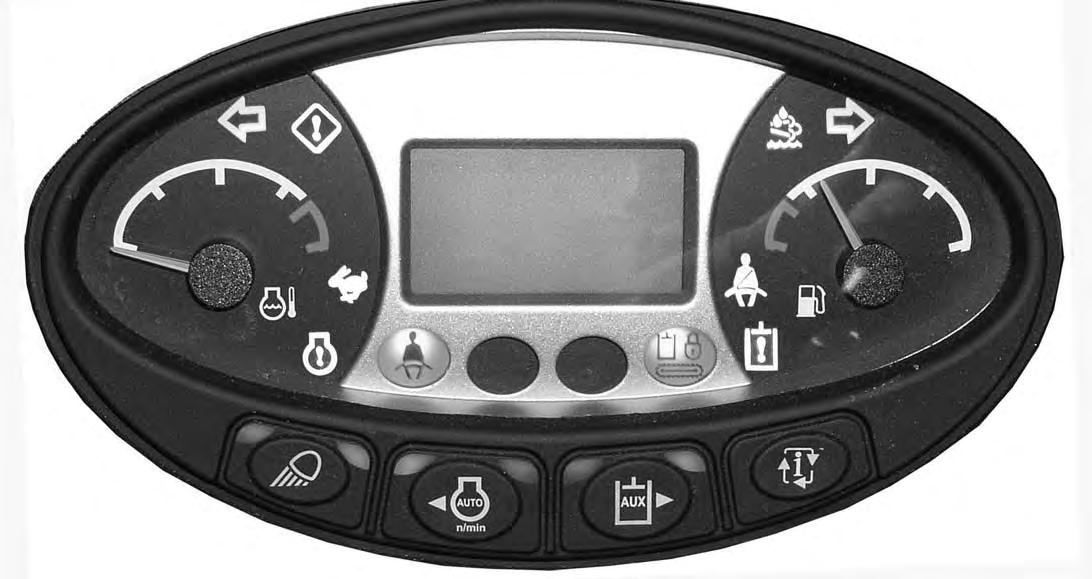
Figure10
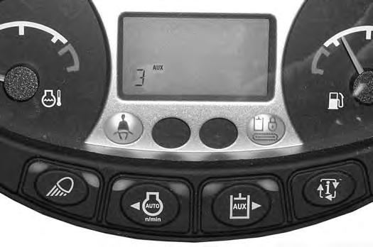
FUNCTION / OPERATION
1 LightsPress once for work lights. (Left green LED illuminates.) Press again to turn all lights off. (Left green LED off.)
Press and hold 5 seconds to display software version in display screen.
2 Auto Idle Feature (NOT USED FOR THIS MODEL)
3 Auxiliary Hydraulic Button (Used With Joystick Switch Activated Auxiliary Hydraulics Only) Press once to enable auxiliary hydraulic function. (Left green LED illuminates.)
See Auxiliary Hydraulics in this manual (See Auxiliary HydraulicsJoystick Controls on Page 54.) or (See Auxiliary Hydraulics - Manual Controls on Page 55.)
4 InformationCycles through (after each button press) (The following information is displayed in the Data Display Screen, Item 6):
•Hourmeter (On startup)
•Job Clock (1 and 2)
•Engine rpm
•Battery voltage
•Maintenance clock (Press and hold 7 seconds when displayed to reset the maintenance clock.)
•Service codes*
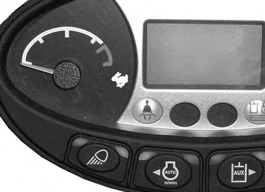
5 Engine Temperature GaugeShows the engine coolant temperature.
INSTRUMENTS AND CONSOLES (CONT’D)
Instrument Panel (Cont’d)
REF. NO. DESCRIPTION
FUNCTION / OPERATION
6 Data Display ScreenThe data display screen shows the Hourmeter at start up and then changes to engine rpm during normal operation of the excavator. When preheat is activated, the display screen will show the remaining preheat time. Can also be used to display Job Clock, Engine rpm, and Selectable Auxiliary Hydraulic Flow. (See Job Clock in this manual). 7 Fuel GaugeShows the amount of fuel in the tank.
8 Seat BeltFasten Seat Belt Reminder - Light stays on for 45 seconds to remind operator to fasten seat belt.
11 Left Console LockoutIcon ON when left console is raised. Icon OFF when left console is lowered.
12 General Warning **Malfunction with one or more machine functions. (See Service Codes in this manual.)
13 High Range Engaged ***Icon is illuminated when two-speed travel is enabled.
coolant temperature high or sensor error.
* See SYSTEM SETUP AND ANALYSIS for Service Code Description. (See DIAGNOSTIC SERVICE CODES on Page 147.)
** Icons will be ON or flashing when diagnostic system indicates a problem. (See DIAGNOSTIC SERVICE CODES on Page 147.)
*** Icons will be flashing when diagnostic system indicates a problem. (See DIAGNOSTIC SERVICE CODES on Page 147.)
INSTRUMENTS AND CONSOLES (CONT’D)
Instrument Panel - Standard (Cont’d)
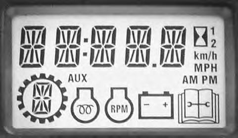
Indicator Icons
The display screen can display the following information:
•Operating hours
•Job Clock (1 and 2)
•Engine rpm
•Battery voltage
•Maintenance clock countdown
•Service codes
The display screen is shown in [Figure11]. The data display will show operating hours upon startup.
INSTRUMENTS AND CONTROLS (CONT’D)

Radio Option
This excavator may be equipped with a radio (Item 1) [Figure12].
NOTE:See DISPLAY (Item 3) in the following table for clock setting instructions.

INSTRUMENT AND CONTROLS (CONT’D)
Radio (Cont’d)
REF. NO. DESCRIPTION
FUNCTION / OPERATION
1POWERPress to turn ON; press again to turn OFF.
2MUTEPress to mute audio output; MUTE will appear in display screen; press again to turn OFF.
3DISPLAYPress to toggle between function mode (showing tuner frequency, auxiliary input, weather band information, or timer) and clock mode. Press and hold to enter clock setting mode; use FREQUENCY DOWN (TUN -) button to adjust hours and FREQUENCY UP (TUN +) button to adjust minutes; normal operation will resume automatically.
4BANDPress to select tuner mode. Press to cycle through 2 AM (MW) bands and 3 FM bands.
5AUXILIARYPress to select Auxiliary Input mode. Portable audio device (MP3 player) must be attached to auxiliary input jack.
6WEATHER BANDPress to select weather band; use FREQUENCY UP (TUN +) and FREQUENCY DOWN (TUN -) buttons to adjust to the clearest station. The weather alert feature, if activated, will automatically switch from the current function to the weather band if a weather warning is received. See AUDIO / MENU ADJUSTMENT in this table.
7TIMERPress to access timer mode. Press to start the timer function; press again to stop timer; press again to resume timer or press and hold to reset timer and exit from timer mode.
8DISPLAY SCREENDisplays the time, frequency, and activated functions.
9VOLUME UPAdjusts volume up; current volume (0 - 40) will appear briefly in display screen.
10AUDIO / MENU ADJUSTMENT AUDIO ADJUSTMENT: Press to cycle through bass, treble, and balance settings; use VOLUME UP (VOL +) and VOLUME DOWN (VOL -) buttons to adjust when desired option is displayed; normal operation will resume automatically.
MENU ADJUSTMENT: Press and hold for 3 seconds to enter menu adjustment settings; press to cycle through the following settings; use VOLUME UP (VOL +) and VOLUME DOWN (VOL -) buttons to adjust when desired option is displayed; normal operation will resume automatically.
• Beep Confirm (On or Off) - Determines if beep will sound with each button press.
• Operation Region (USA or Europe) - Selects the appropriate region.
• Clock Display (12 or 24) - Selects a 12-hour or 24-hour clock display.
• Display Brightness (Low, Medium, or High) - Determines brightness level of display screen.
• Backlight Color (Amber or Green) - Determines backlight color of display screen.
• Power On Volume (0 - 40) - Selects default volume setting when radio is turned on.
• WB Alert (On or Off) - Determines if weather band alert feature is activated.
11FREQUENCY DOWNPress to manually tune the radio frequency down.
12FREQUENCY UPPress to manually tune the radio frequency up.
13VOLUME DOWNAdjusts volume down; current volume (0 - 40) will appear briefly in display screen.
14SEEK FREQUENCY DOWN Press to automatically tune frequency down to next strong station.
15SEEK FREQUENCY UP Press to automatically tune frequency up to next strong station.
16PRESET STATIONSUsed to store and recall stations for each AM and FM band. Press and hold to store current station; press button to recall station.
17AUXILIARY INPUT JACK Connect line output of portable audio device (MP3 player) to 3,5 mm (1/8 in) jack and press AUXILIARY button.
INSTRUMENTS AND CONTROLS (CONT’D)
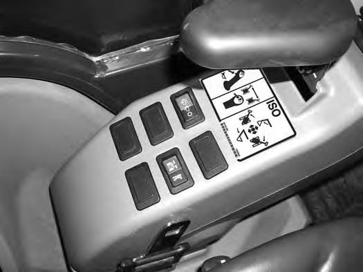
STD / ISO Selector Valve
The STD / ISO selector valve (if equipped) is located to the left of the operator’s seat.
Figure14
The joystick hydraulic function can be switched from Standard control pattern to ISO control pattern.
Rotate the lever (Item 1) counterclockwise (Item 2) to select STANDARD Control Pattern. Rotate the lever clockwise (Item 3) to select ISO Control Pattern [Figure14]
Raising And Lowering The Console
Raise the console before exiting the cab.
Figure15
Pull up on the release handle [Figure15]. The lift spring will assist in raising the console.
Lower the console before operating the excavator.
Push down on the console [Figure15] until the latch is engaged.

NOTE:When the console is raised, the hydraulic and traction system functions are locked and will not operate.
If the engine stops, the boom / bucket (attachments) can be lowered to the ground using hydraulic pressure in the accumulator.
The control console must be in the locked down position, and the key switch in the ON position.
INSTRUMENTS AND CONTROLS (CONT’D)

Two-Speed Travel
Figure16
Press the button (Item 1) [Figure16] to engage the high range. Press a second time to disengage.
NOTE:When engaging high range, two audible beeps will be heard. When engaging low range, one audible beeps will be heard.
Auto Shift Drive Motors (If Equipped)
The travel motors may be equipped with an auto shift feature that senses hydraulic pressure. When in high range, the travel motors will automatically shift to low range when more torque is required and return to high range when hydraulic pressure decreases.
NOTE:Always set the travel speed to low range when loading or unloading the excavator onto a transport vehicle.
When high range is engaged, the two-speed travel icon (Item 1) [Figure17] will illuminate.
Press the button (Item 1) [Figure16] again to disengage.
OPERATOR CANOPY (ROPS / TOPS)
Description
The Bobcat excavator has an operator canopy (ROPS / TOPS) as standard equipment to protect the operator if the excavator is tipped over. The seat belt must be worn for ROPS / TOPS protection.
Check the ROPS / TOPS canopy, mounting, and hardware for damage. Never modify the ROPS / TOPS canopy. Replace the canopy and hardware if damaged. See your Bobcat dealer for parts.
ROPS / TOPS - Roll-Over Protective Structure per ISO 12117-2, and Tip-Over Protective Structure per ISO 12117.
Warning
Never modify operator cab by welding, grinding, drilling holes or adding attachments unless instructed to do so by Bobcat Company. Changes to the cab can cause loss of operator protection from rollover and falling objects, and result in injury or death.
W-2069-0200
OPERATOR CAB (ROPS / TOPS)
Description
The Bobcat excavator has an optional operator cab (ROPS / TOPS) as standard equipment to protect the operator if the excavator is tipped over. The seat belt must be worn for ROPS / TOPS protection.
Check the ROPS / TOPS cab, mounting, and hardware for damage. Never modify the ROPS / TOPS cab. Replace the cab and hardware if damaged. See your Bobcat dealer for parts.
ROPS / TOPS - Roll-Over Protective Structure per ISO 12117-2, and Tip-Over Protective Structure per ISO 12117.
Warning
Never modify operator cab by welding, grinding, drilling holes or adding attachments unless instructed to do so by Bobcat Company. Changes to the cab can cause loss of operator protection from rollover and falling objects, and result in injury or death.
W-2069-0200
OPERATOR CAB (ROPS / TOPS) (CONT’D)

Cab Door

OPERATOR CAB (ROPS / TOPS) (CONT’D)

Front Window
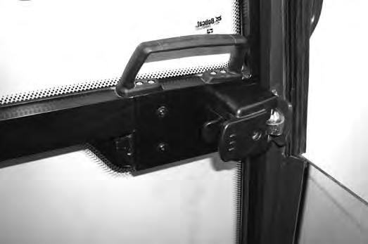
Opening The Front Window
Figure23
Press the window latch button (Item 1) [Figure23] (both sides).
When the window is fully raised, the latch (Item 1) [Figure25] (both sides) will close on the bracket in the latched position.
Pull down and forward slightly on the window to make sure it is fully latched.
Closing The Front Window
Use both window grab handles to support the window while pressing the window latch button (Item 2) [Figure25] (both sides).
Use both window grab handles (Item 1) [Figure24] to pull the window down fully.
Press the top of the window in until the latch locks into the latched position (both sides) [Figure23]

Pull inward and upward slightly on the window to make sure it is fully latched in the closed position.
Use both window grab handles (Item 1) [Figure24] to pull the top of the window in.
Continue moving the window in and up over the operator’s head until the window is fully raised.
OPERATOR CAB (ROPS / TOPS) (CONT’D)

Front Wiper
Figure26
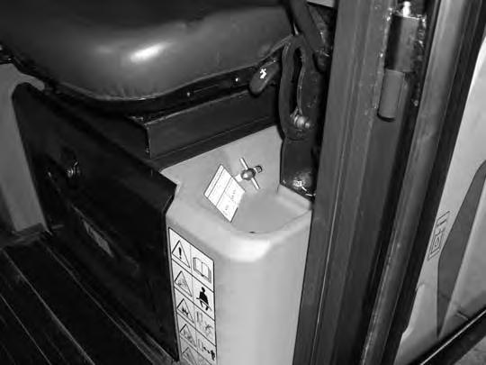
Window Washer Reservoir
Figure27
NOTE:When temperatures are to reach below freezing, use a washer fluid that is recommended for use in cold temperatures to avoid damage to the washer reservoir.

OPERATOR CAB (ROPS / TOPS) (CONT’D)

Right Side Window
Opening The Right Front Window
Heating And Ventilation Ducting
Press down on the latch (Item 1) [Figure28] located at the front of the front window.
Pull the latch (Item 1) [Figure29] backward to open the window until the desired stop. Release the latch and latch the window in place.


Closing The Right Front Window
Press down on the latch (Item 1) [Figure28] and push the latch forward to close the window.
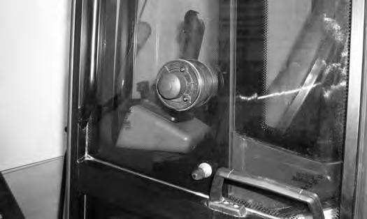
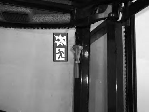
Emergency Exit
The door, the rear window and the front window provide exits.
Side Or Rear Window
Figure31
If emergency exit requires breaking a window, use the supplied hammer (Item 1) [Figure31] located on the left rear side of the cab.
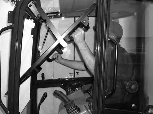
Front Window
Figure33
Remove the hammer from the storage position and strike the glass with the pointed end of the hammer [Figure32]
Use the hammer to remove broken glass from the edge of the window before exiting.

Open the front window and exit [Figure33]
NOTE:If the excavator has a Special Applications Kit installed, the front window is NOT an emergency exit.
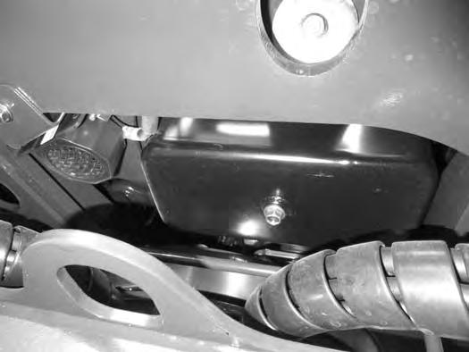
This excavator can be equipped with a motion alarm system. The motion alarm is located inside the rear (Item 1) [Figure34] of the excavator.

Warning
This machine is equipped with a motion alarm. ALARM MUST SOUND! when operating forward or backward.
Failure to maintain a clear view in the direction of travel could result in serious injury or death.
The operator is responsible for the safe operation of this machine.
W-2786-0309
The motion alarm will sound when the operator moves the travel control levers (Item 1) [Figure35] in either the forward or reverse direction.
If alarm does not sound or for adjustment instructions, see inspection and maintenance instructions for the motion alarm system in the preventive maintenance section of this manual. (See MOTION ALARM SYSTEM on Page 107.)
Travel Controls
Forward And Reverse Travel
NOTE:The following procedures describe forward, reverse, left and right as seated in the operator’s seat.
Turning Right Turn
Figure36
Put the blade so that it is at the front of the machine (as you sit in the operator’s seat). Slowly move both steering levers* (Item 1) [Figure35] forward for forward travel; backward for reverse travel.
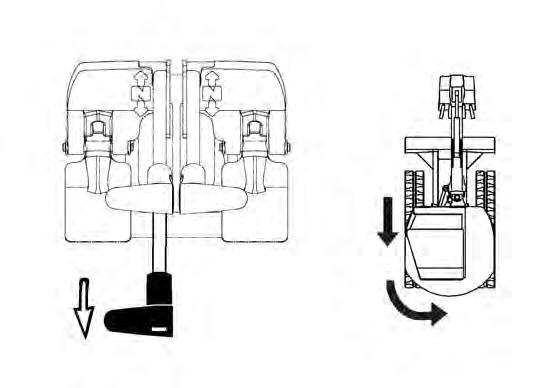
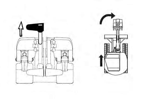
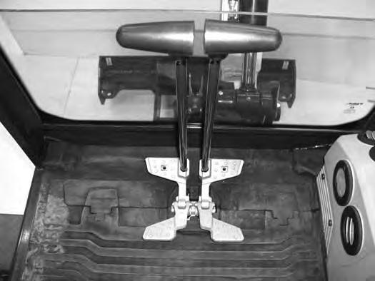
* Travel can also be controlled with foot pedals (Item 2) [Figure35]. Pivot the heel of the pedals forward for additional space on the floor.
Warning
AVOID INJURY OR DEATH
•Check the blade location before traveling. When the blade is to the rear, operate the steering levers / foot pedals in the opposite direction to when the blade is in the front.
•Move the steering levers / foot pedals slowly. Abrupt lever motion will cause the machine to jerk.
W-2235-0396
Push the left steering lever forward to turn right [Figure36] while traveling forward.
Pull the left steering lever backward to turn right while traveling backward [Figure37]
TRAVEL CONTROLS (CONT’D)
Turning (Cont’d)
Counter-Rotation Right Turn
Figure38
Counter-Rotation
NA1459A
Push the left steering lever forward and pull the right steering lever backward [Figure38]


Left Turn
Figure39
Push the right steering lever forward to turn left while traveling forward [Figure39]
Pull the right steering lever backward to turn left while traveling backward [Figure40].
Counter-Rotation Left Turn
Figure41
HYDRAULIC CONTROLS Description
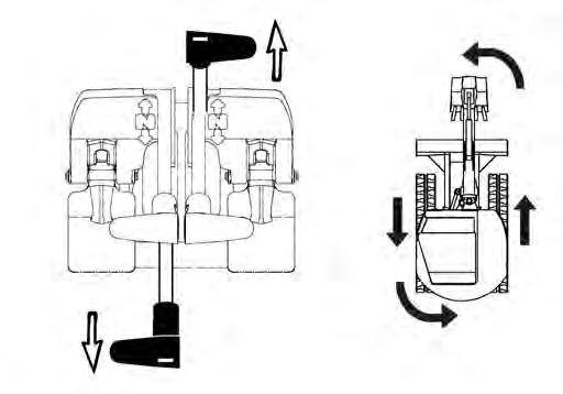
The work equipment (boom, arm, bucket, and upperstructure slew) is operated by using the left and right control levers (joysticks). These joysticks can be used in either a STANDARD Control Pattern [Figure42] and [Figure43] or in the ISO Control Pattern [Figure44] and [Figure45].
STANDARD Control Pattern
Left Control Lever (Joystick)
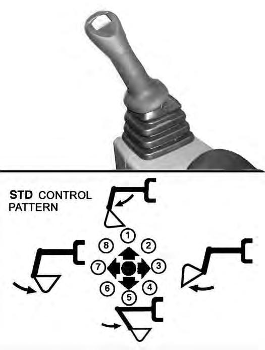

Figure42
P113002A
The left lever (joystick) is used to operate the boom and slew the upperstructure [Figure42]
1. Boom lower.
2. Boom lower and slew right.
3. Slew right.
4. Boom raise and slew right.
5. Boom raise.
6. Boom raise and slew left.
7. Slew left.
8. Boom lower and slew left.
Right Control Lever (Joystick)
Figure43
The right lever (joystick) is used to operate the arm and bucket [Figure43]
1. Arm out.
2. Arm out and bucket dump.
3. Bucket dump.
4. Arm in and bucket dump.
5. Arm in.
6. Arm in and bucket curl.
7. Bucket curl.
8. Arm out and bucket curl. WARNING
AVOID INJURY OR DEATH
Before leaving the machine:
•Lower the work equipment to the ground.
•Lower the blade to the ground.
•Stop the engine and remove the key.
•Raise the control console.
W-2780-0109
HYDRAULIC CONTROLS (CONT’D)
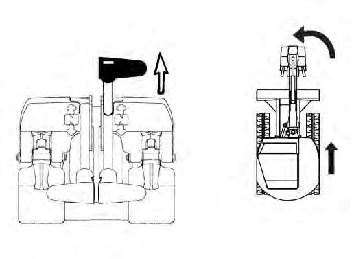
ISO Control Pattern
Left Control Lever (Joystick)
Figure44
The left lever (joystick) is used to operate the arm and slew the upperstructure [Figure44].

1. Arm out.
2. Arm out and slew right.
3. Slew right.
4. Arm in and slew right.
5. Arm in.
6. Arm in and slew left.
7. Slew left.
8. Arm out and slew left.
Right Control Lever (Joystick)
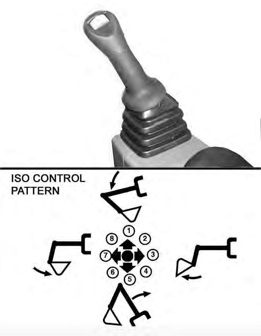
Figure45
The right lever (joystick) is used to operate the boom and bucket [Figure45]
1. Boom lower.
2. Boom lower and bucket dump.
3. Bucket dump.
4. Boom raise and bucket dump.
5. Boom raise.
6. Boom raise and bucket curl.
7. Bucket curl.
8. Boom lower and bucket curl. WARNING
AVOID INJURY OR DEATH
Before leaving the machine:
•Lower the work equipment to the ground.
•Lower the blade to the ground.
•Stop the engine and remove the key.
•Raise the control console.
W-2780-0109
HYDRAULIC CONTROLS (CONT’D)
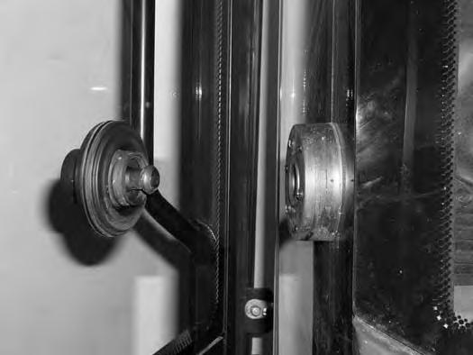
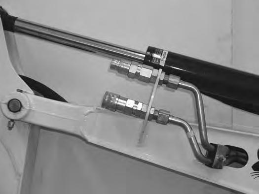
Quick Couplers
Warning
AVOID BURNS
Hydraulic fluid, tubes, fittings and quick couplers can get hot when running machine and attachments. Be careful when connecting and disconnecting quick couplers.
W-2220-0396
Warning
AVOID INJURY OR DEATH
Diesel fuel or hydraulic fluid under pressure can penetrate skin or eyes, causing serious injury or death. Fluid leaks under pressure may not be visible. Use a piece of cardboard or wood to find leaks. Do not use your bare hand. Wear safety goggles. If fluid enters skin or eyes, get immediate medical attention from a physician familiar with this injury.
W-2072-0807
To Connect:
If equipped with flush face couplers, remove any dirt or debris from the surface of both the male and female couplers, and from the outside diameter of the male coupler. Visually check the couplers for corroding, cracking, damage, or excessive wear, if any of these conditions exist, the coupler(s) (Item 2) [Figure46] must be replaced.
Install the male coupler into the female coupler. Full connection is made when the ball release sleeve slides forward on the female coupler.
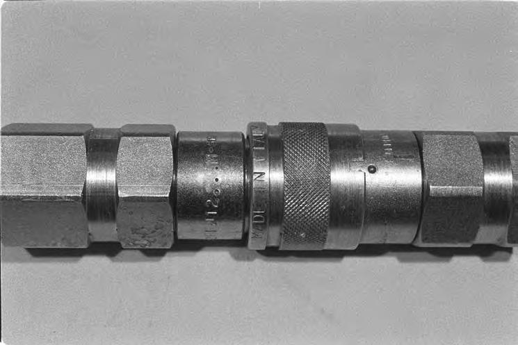
To Disconnect:
The excavator is supplied with hydraulic lines (Item 1) [Figure46] that supply the hydraulic fluid for attachments.
Optional flush faced couplers (Item 2) [Figure46] are available. See your Bobcat dealer for flush face couplers.
Hold the male coupler (Item 1). Retract the sleeve (Item 2) [Figure47] on the female coupler until the couplers disconnect.
HYDRAULIC CONTROLS (CONT’D)
Auxiliary Hydraulics - Joystick Controls
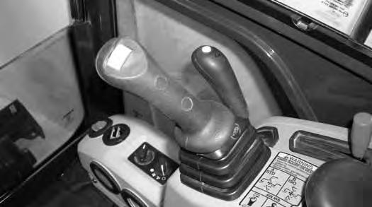
If equipped with the auxiliary hydraulic switch (Item 1) [Figure49] see the following information. If equipped with the auxiliary hydraulic pedal (Item 1) [Figure51] (See Auxiliary Hydraulics - Manual Controls on Page 55.)
Continuous Hydraulic Flow
Press the button (Item 2) [Figure49] on the front of the handle to provide continuous flow to the female coupler.
NOTE: Pressing the switch (Item 1) to the left while pressing the button (Item 2) [Figure49] on the front of the handle will provide continuous flow to the male coupler.
Press the button (Item 2) [Figure49] a second time to stop auxiliary flow to the quick couplers.
NOTE:Reverse flow can cause damage to some attachments. Use reverse flow with your attachment only if approved. See your attachment Operation & Maintenance Manual for detailed information.
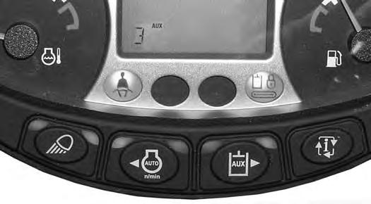
To change the auxiliary flow, press the Auxiliary Hydraulics button (Item 1) to toggle through the settings, each time the button is pressed, the next setting will appear in the data display (Item 2) [Figure48]. Once the desired setting is selected, it will stay at that setting until a different auxiliary flow is selected by the operator. (Example: Even if the engine was STOPPED, if Aux2 has been selected, after key OFF and engine restart, the Aux2 setting will still be the active hydraulic flow when the machine is started.)
Examples For Selecting Auxiliary Hydraulic Flow And The Attachments Used:
Aux Flow Setting
Flow Attachments
Aux3MaximumBreaker, Auger
Aux2MediumClamp
Aux1LowAttachments requiring very low flow for controllability
NOTE:Use only approved attachments for your model excavator. Attachments are approved for each model of excavator based on various factors. Using unapproved attachments could cause damage to the attachment or to the excavator.
Selectable Auxiliary Hydraulics Flow
Press the auxiliary hydraulics button (Item 1) once to enable the selectable hydraulic flow. The light (Item 2) [Figure48] will be illuminated when the selectable auxiliary hydraulics are enabled.
Press the button (Item 1) a second time to disable the auxiliary hydraulics. The light (Item 2) [Figure48] will turn OFF.
NOTE:If the auxiliary hydraulics are enabled when the engine is turned OFF, they will stay enabled when the engine is restarted.
Press the Auxiliary Hydraulics button (Item 1) (an audible beep will sound each time the auxiliary button is pressed). The last selected auxiliary hydraulic flow (Aux3, Aux2 or Aux1) will appear in the data display (Item 2). The LED (Item 3) [Figure48] will be illuminated.
Move the switch (Item 1) [Figure49] on the right control lever to the right to supply hydraulic flow to the female coupler. Move the switch to the left to supply hydraulic flow to the male coupler. If you move the switch halfway, the auxiliary functions move at approximately one-half speed.
Press the button (Item 2) [Figure49] on the front of the handle to provide continuous selectable flow to the female coupler.
NOTE: Pressing the switch (Item 1) to the left while pressing the button (Item 2) [Figure49] on the front of the handle will provide continuous selectable flow to the male coupler.
Press the button (Item 2) [Figure49] a second time to stop auxiliary flow to the quick couplers.
HYDRAULIC CONTROLS (CONT’D)
Relieve Hydraulic Pressure - With Joystick Controls (Excavator And Attachment)
NOTE: The following is for auxiliary hydraulics with the joystick switch (Item 1) [Figure49] only. For manual auxiliary hydraulic controls, see [Figure51].
Excavator:
Put the attachment flat on the ground. Stop the engine and turn the key switch to ON.
NOTE: The left console must be fully lowered for relieving hydraulic pressure.
NOTE:Excavator engine must have recently been started to relieve hydraulic pressure.
Figure50
If the auxiliary hydraulics are disabled, press AUX HYD button (Item 1) [Figure50] and then move the switch (Item 1) [Figure49] to the right and left several times.
If the auxiliary hydraulics are enabled, then move the switch (Item 1) [Figure49] to the right and left several times.
Attachments:
•Follow procedure above to relieve hydraulic pressure in excavator.
•Connect male coupler from attachment to female coupler of excavator then repeat procedure above. This will relieve pressure in the attachment.
•Connect the female coupler from the attachment.
Hydraulic pressure in the auxiliary hydraulic system can make it difficult to engage quick couplers to an attachment.
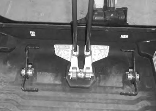
Auxiliary Hydraulics - Manual Controls
If equipped with the auxiliary hydraulic pedal (Item 1) [Figure51] control, see the following information. If equipped with the joystick auxiliary hydraulic switch (Item 1) [Figure49] (See Auxiliary Hydraulics - Joystick Controls on Page 54.)
Figure51
Press the toe of the pedal (Item 2) [Figure51] to supply hydraulic flow to the female coupler (if equipped).
Press the heel of the pedal (Item 3) [Figure51] to supply hydraulic flow to the male coupler (if equipped).
Relieve Hydraulic Pressure - With Manual Controls (Excavator And Attachment)
Put the attachment flat on the ground.
Stop the engine.
Excavator:
With the engine off, move the pedal (Item 1) [Figure51] in both directions several times.
Attachments:
•Follow the procedure above to release pressure in the excavator.
•Connect the male coupler from attachment to the female coupler of the excavator. Then repeat procedure above. This will release pressure in the attachment.
•Connect the female coupler from the attachment.
Hydraulic pressure in the auxiliary hydraulic system can make it difficult to engage quick couplers to an attachment.
Engine Speed Control
Setting Engine Speed (RPM)
Figure52
The engine speed control lever (Item 1) [Figure52] controls engine rpm.
Move the engine speed control lever back (Item 2) to reduce engine rpm. Move the engine speed control dial forward (Item 3) [Figure52] to increase engine rpm.
Blade Control Lever


Raising And Lowering Blade
Figure53
Push the Blade / Track Retraction - Expansion Switch (Item 1) [Figure53] to the Blade position.
Figure54
Move the Blade / Track Retraction - Expansion Lever forward to lower the blade [Figure54]
Move the Blade / Track Retraction - Expansion Lever backward to raise the blade [Figure54]
NOTE: Keep blade lowered for increased digging performance.