17 minute read
AIR CLEANER SERVICE


Replacing Filter Element
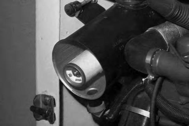
Condition Indicator:
Replace the large (outer) filter element only when the red ring shows in the window of the condition indicator (Item 1) [A]
NOTE:Before replacing the filter element, push the button on the condition indicator (Item 2) [A]. Start the engine. If the red ring does not show, do not replace the filter element.
Replace the inner filter every third time the outer filter is replaced or when the red ring still shows in the indicator window after the outer filter has been replaced.
Remove the dust cover wing nut (Item 1) [B]


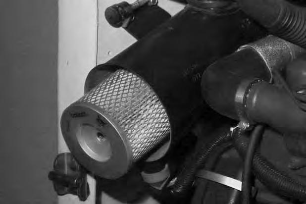
Remove the dust cover [C]
Remove the wing nut (Item 1) [C] from the large air filter element.
AIR CLEANER SERVICE (Cont’d)
Replacing Filter Element (Cont’d)
Outer Element:
Remove the outer filter element [A]
NOTE:Be sure all sealing surfaces are free of dirt and debris.
Install the new filter element and washer and tighten the wing nut.
NOTE:Be sure sealing washer(s) is installed in its original location.
Install the dust cover and tighten the wing nut. Check the air intake hose for damage. Check the air cleaner housing for damage. Check to make sure all connections are tight.
Inner Element:
Only replace the inner filter element under the following conditions:
• Replace the inner filter element every third time the outer filter is replaced.
• Press the button to remove the red ring in the condition indicator after the outer element has been replaced. Start the engine and run at full RPM. If the red ring shows again, replace the inner filter element.
Remove the inner filter wing nut (Item 1) [B].
Remove the inner filter [C].
Install a new filter and tighten the wing nut.
Fuel System
Fuel Specifications
Use only clean, high quality diesel fuel, Grade No. 2 or Grade No. 1.
The following is one suggested blending guideline which should prevent fuel gelling problems:
Temp. F° (C°) No. 2No.1
+15°(9°) 100% 0%
Down to –20° (–29°)50% 50%
Below –20° (29°) 0% 100%
Contact your fuel supplier for local recommendations.
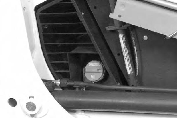
Stop and cool the engine before adding fuel. NO SMOKING! Failure to obey warnings can cause an explosion or fire.
Remove the fuel fill cap (Item 1) [A]
Use a clean, approved safety container to add fuel of the correct specifications. Add fuel only in an area that has free movement of air and no open flames or sparks. NO SMOKING! [B].
Install and tighten the fuel fill cap [A]
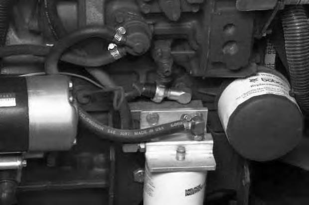
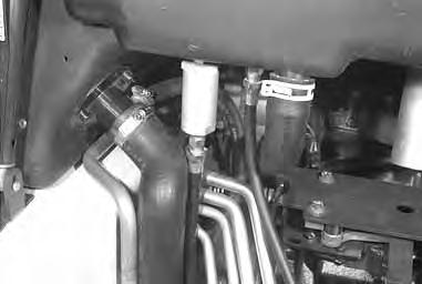
Fuel Filter
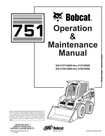
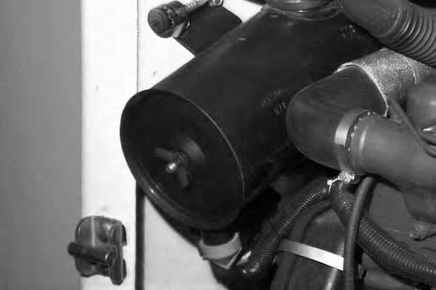
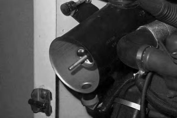
See the SERVICE SCHEDULE Page 37 for the service interval when to remove the water from the fuel filter.
Loosen the drain (Item 1) [C] at the bottom of the filter element to drain water from the filter.
See the SERVICE SCHEDULE Page 37 for the service interval when to replace the fuel filter.
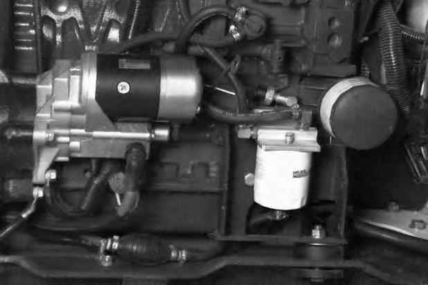
Remove the filter element (Item 2) [C]
Clean the area around the filter housing. Put oil on the seal of the new filter element.
Install the fuel filter, and hand tighten.
Remove the air from the fuel system. (See Removing Air From the Fuel System Page 51.)
Always clean up spilled fuel or oil. Keep heat, flames, sparks or lighted tobacco away from fuel and oil. Failure to use care around combustibles can cause explosion or fire which can result in injury or death.
FUEL SYSTEM (Cont’d)
Removing Air From The Fuel System 15.
After replacing the fuel filter element or when the fueltank has run out of fuel, the air must be removed from the fuel system prior to starting the engine.

Diesel fuel or hydraulic fluid under pressure can penetrate skin or eyes, causing serious injury or death. Fluid leaks under pressure may not be visible. Use a piece of cardboard or wood to find leaks. Do not use your bare hand. Wear safety goggles. If fluid enters skin or eyes, get immediate medical attention from a physician familiar with this injury.
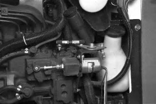
Open the vent (Item 1) [A] on the fuel filter housing.
Operate the hand pump (priming bulb) (Item 2) [A] until fuel flows from the vent with no air bubbles.
Close the vent (Item 1) [A] on the fuel filter housing.
Open the vent (Item 1) [B] on the fuel injection pump.
Operate the hand pump (priming bulb) (Item 2) [A] until the pump feels solid.
Tighten the vent plug [B]
Start the engine. It may be necessary to open the vent plug (at the fuel injection pump) briefly until the engine runs smoothly.

Engine Lubrication System
16.
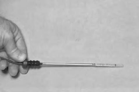
Checking Engine Oil
Check the engine oil level every day before starting the engine for the work shift.
Open the rear door and remove the dipstick (Item 1) [A] Keep the oil level between the marks on the dipstick. Use a good quality motor oil that meets API Service Classification of CD or better (See Oil Chart below).
Oil Chart 17.
RECOMMENDED SAE VISCOSITY NUMBER (LUBRICATION OILS FOR DIESEL ENGINE CRANKCASE)
SAE 10W–30
SAE 15W–40
SAE 40W or 20W–50
SAE 30W
* SAE 5W–30
SAE 20W–20
SAE 10W
–40
C° –34–29–23–18–13–7–1+4+10+15+21+27+32+38+43+49 F° –30–20–100+10+20+30+40+50+60+70+80+90+100+110+120 2
TEMPERATURE RANGE ANTICIPATED BEFORE NEXT OIL CHANGE (DIESEL ENGINES MUST USE API CLASSIFICATION CD, CF4, CG4 ) * Can be used ONLY when available with appropriate diesel rating.
Replacing Oil And Filter
See the SERVICE SCHEDULE Page 37 for the service interval for replacing the engine oil and filter.

Run the engine until it is at operating temperature. Stop the engine.
Open the rear door.
Remove the drain plug (Item 2) [A]
Drain the oil into a container and dispose of used oil in an environmentally safe manner.
–40 1 751 Bobcat Loader Operation & Maintenance Manual 52
ENGINE LUBRICATION SYSTEM (Cont’d)

Replacing Oil And Filter (Cont’d)
Remove the oil filter (Item 1) [A].
Clean the filter housing surface.
Put clean oil on the new oil filter gasket.
Install the filter and hand tighten.
Install and tighten the drain plug.
Remove the filler cap (Item 2) [A]
Put oil in the engine. (See SPECIFICATIONS Page 87, for Capacity) [A]. (See Oil Chart, Page 52.)
Start the engine and let it run for several minutes.
Stop the engine.
Check for leaks at the oil filter and check the oil level.
Add oil as needed if it is not at the top mark (Item 1) [B] on the dipstick.
Always clean up spilled fuel or oil. Keep heat, flames, sparks or lighted tobacco away from fuel and oil. Failure to use care around combustibles can cause explosion or fire which can result in injury or death.
Engine Cooling System
Check the cooling system every day to prevent over–heating, loss of performance or engine damage.
Wear safety glasses to prevent eye injury when any of the following conditions exist:
• When fluids are under pressure.
• Flying debris or loose material is present.
• Engine is running.
• Tools are being used.
Cleaning The Cooling System
Raise the rear grill.
W–2019–1285
Use air pressure or water pressure to clean the top of the oil cooler [A]

Raise the oil cooler and clean the top of the radiator [B]

Check cooling system for leaks.
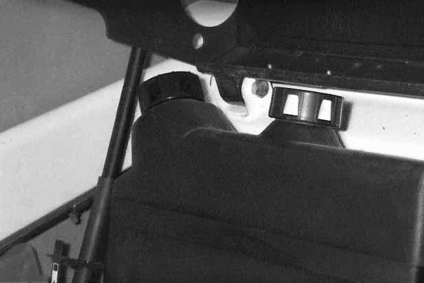
Checking The Coolant Level
Open the rear door.
Check the coolant level in the coolant recovery tank (Item 1) [C]
The coolant recovery tank must be 1/3 full.
Avoid Engine Damage
Always use the correct ratio of water to antifreeze.
Too much antifreeze reduces cooling system efficiency and may cause serious premature engine damage.
Too little antifreeze reduces the additives which protect the internal engine components; reduces the boiling point and freeze protection of the system.
Always add a premixed solution. Adding full strength concentrated coolant can cause serious premature engine damage.
I–2124–0497
ENGINE COOLING SYSTEM (Cont’d) Replacing The Coolant
Do not remove radiator cap when the engine is hot. You can be seriously burned.
W–2070–1285
Open the rear door. Open the rear grill.
Remove the radiator cap (Item 1) [A].
Connect a hose to the engine block drain valve (Item 1) [B]
Open the drain valve and drain all of the coolant into a container.
Close the drain valve.
Mix the coolant in a separate container. (See SPECIFICATIONS Page 87, for correct capacity.)
NOTE:The loader is factory filled with propylene glycol coolant (purple color). DO NOT mix propylene glycol with ethylene glycol.
Add premixed coolant, 47% water and 53% propylene glycol to the recovery tank if the coolant level is low.
One gallon and one pint (4,3 L) of propylene glycol mixed with one gallon (3,8 L) of water is the correct mixture of coolant to provide a –34°F (–37°C) freeze protection.
Use a refractometer to check the condition of propylene glycol in your cooling system.
Fill the radiator with the premixed coolant. Install the radiator cap.

Fill the coolant recovery tank 1/3 full.
Run the engine until it is at operating temperature. Stop the engine.
Check the coolant level in the recovery tank when cool.
Add coolant to the recovery tank as needed.
Avoid Engine Damage
Always use the correct ratio of water to antifreeze.
Too much antifreeze reduces cooling system efficiency and may cause serious premature engine damage.
Too little antifreeze reduces the additives which protect the internal engine components; reduces the boiling point and freeze protection of the system.
Always add a premixed solution. Adding full strength concentrated coolant can cause serious premature engine damage.
I–2124–0497
Alternator Belt
Adjusting
Stop the engine.
Raise the operator cab. (See Raising The Operator Cab Page 40.)
Loosen the alternator mounting bolt (Item 1) [A]
Loosen the adjustment bolt (Item 2) [A]
Move the alternator until the belt has 5/16 inch (8,0 mm) movement at the middle of the belt span with 15 lbs. (66 N) of force.

Tighten the adjustment bolt and mounting bolt.
Lower the operator cab.
ELECTRICAL SYSTEM Description
The loader has a 12 volt, negative ground alternator charging system.
The electrical system is protected by fuses located in the engine compartment. The fuses will protect the electrical system when there is an electrical overload. The reason for the overload must be found before starting the engine again.
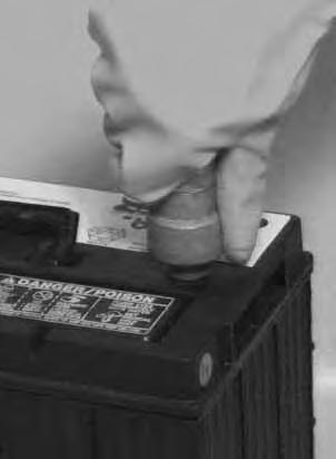
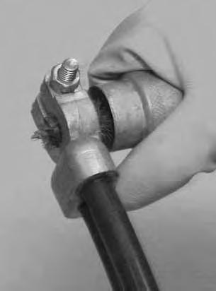
Cleaning The Battery Terminals
The battery cables must be clean and connections tight. Clean the terminals and cable ends [A]
Remove acid or corrosion from the battery and cables with a sodium bicarbonate (baking soda) and water solution [B]

Check the electrolyte level in the battery. Add distilled water as needed.
Put Battery Saver P/N 6664458 or grease on the battery terminals and cable ends to prevent corrosion.
Batteries contain acid which burns eyes and skin on contact. Wear goggles, protective clothing and rubber gloves to keep acid off body.
In case of acid contact, wash immediately with water. In case of eye contact get prompt medical attention and wash eye with clean, cool water for at least 15 minutes.
If electrolyte is taken internally drink large quantities of water or milk! DO NOT induce vomiting. Get prompt medical attention.
W–2065–1296
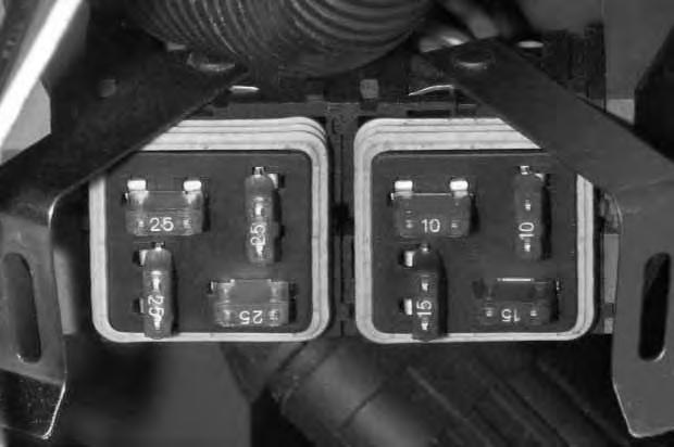
Fuse Location
The electrical system is protected by eight fuses (Item 1) [C] located in the fuse block (Item 1) [D].
The fuse block is located in the engine compartment near the engine oil filter [D]
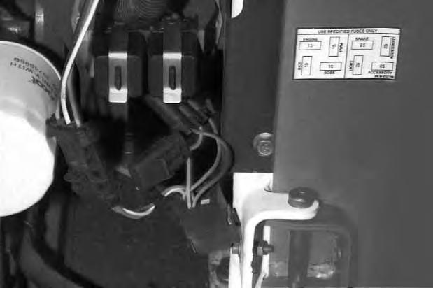
Remove the cover from the fuse block tocheck or replace the fuses.
Fuses protect the electrical system from an overload.
The decal inside the rear door shows the fuse sizes used in loader circuits [D]
ELECTRICAL SYSTEM (Cont’d)
Using A Booster Battery (Jump Starting)
If it is necessary to use a booster battery to start the engine, BE CAREFUL! There must be one person in the operator’s seat and one person to connect and disconnect the battery cables.
Batteries contain acid which burns eyes and skin on contact. Wear goggles, protective clothing and rubber gloves to keep acid off body.
In case of acid contact, wash immediately with water. In case of eye contact get prompt medical attention and wash eye with clean, cool water for at least 15 minutes.
If electrolyte is taken internally drink large quantities of water or milk! DO NOT induce vomiting. Get prompt medical attention.
W–2065–1296
Keep arcs, sparks, flames and lighted tobacco away from batteries. When jumping from booster battery make final connection (negative) at engine frame.
Do not jump start or charge a frozen or damaged battery. Warm battery to 60°F. (16°C.) before connecting to a charger. Unplug charger before connecting or disconnecting cables to battery. Never lean over battery while boosting, testing or charging.
Damage to the alternator can occur if:
• Engine is operated with battery cables disconnected.
The booster battery must be 12 volt.
W–2066–1296
Battery gas can explode and cause serious injury.
The key switch must be in the OFF POSITION.
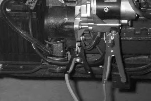
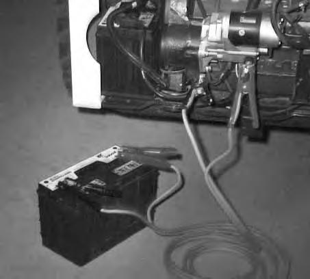
Connect the end of the first cable (Item 1) [A] to the positive (+) terminal of the booster battery. Connect the other end of the same cable (Item 1) [B] to the positive terminal on the starter.
Connect the end of the second cable (Item 2) [A] to the negative (–) terminal of the booster battery. Connect the other end of the same cable (Item 2) [B] to the engine.
Keep cables away from moving parts.
Start the engine
After the engine has started, remove the ground (–) cable (Item 2) [B] first. Remove the cable from the positive terminal on the loader battery.
• Battery cables are connected when using a fast charger or when welding on the loader (Remove both cables from the battery).
• Extra battery cables (booster cables) are connected wrong.
I–2023–1285
Electrical System


Removing And Installing The Battery 18.
Open the rear door.
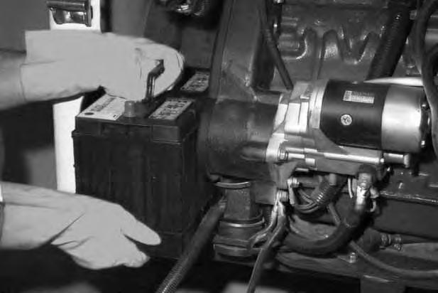
Disconnect the negative (–) battery cable (Item 1) [A] from the battery.
Disconnect the positive (+) battery cable (Item 1)[B] from the battery.
Remove the battery hold down clamp (Item 1) [C].
ELECTRICAL SYSTEM (Cont’d)
Removing And Installing The Battery (Cont’d)
Remove the battery from the loader [A].
Always clean the terminals and cable ends when installing a new battery [B].
When installing the battery in the loader, do not touch any metal parts with the battery terminals.

Connect and tighten the battery cables. Connect the negative (–) cable last to prevent sparks.

HYDRAULIC/HYDROSTATIC SYSTEM Checking And Adding Fluid
Use only recommended fluid in the hydraulic system. (See SPECIFICATIONS Page 87.)


Stop the loader on a level surface.
Lower the lift arms and tilt the Bob–Tach fully back.
Stop the engine.
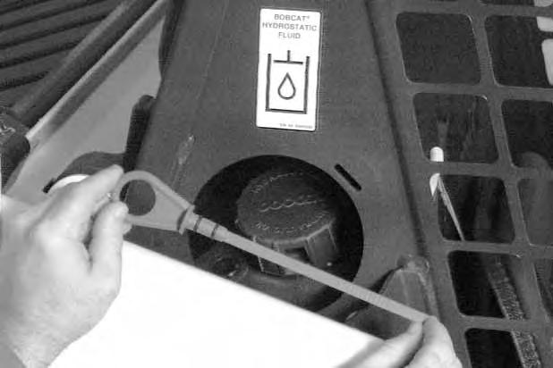
Remove the dipstick (Item 1) [A]
The fluid level must be between the marks on the dipstick [B]
If fluid is needed, remove the fill cap (Item 2) [A]
Clean the hydraulic reservoir fill screen [C].
Add the fluid as needed to bring the level to the top mark on the dipstick [B]
Replacing Hydraulic/Hydrostatic Filter 19.
See the SERVICE SCHEDULE Page 37 for the correct service interval.
Open the rear door.
Remove the filter element (Item 1) [D]
Clean the surface of the filter housing where theelement seal contacts the housing.
Put clean oil on the rubber seal of the filter element.
Install and hand tighten the filter element.
HYDRAULIC/HYDROSTATIC SYSTEM (Cont’d)
Replacing Hydraulic Fluid
See the SERVICE SCHEDULE Page 37 for the service interval.
The fluid must also be replaced if it becomes contaminated or after major repairs.
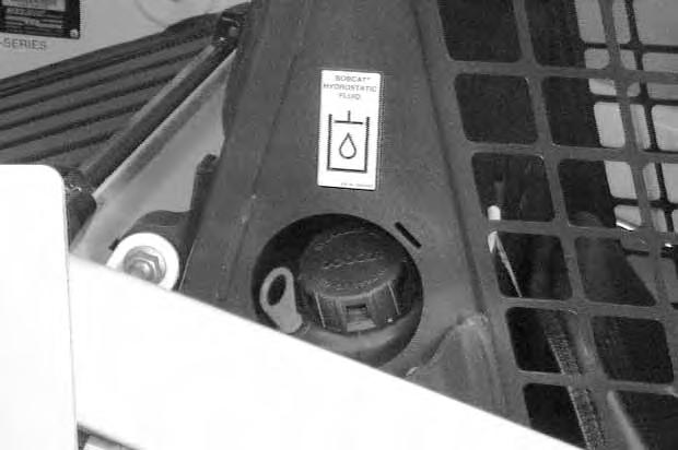
Remove the reservoir fill cap (Item 1) [A]
NOTE:Be sure the rubber gasket is installed on the fill cap [A].
Raise the operator cab. (See Raising the Operator Cab Page 40.)
Disconnect the hose (Item 1)[B] from the case drain filter located on the reservoir. Use a plug and cap on the filter and case drain hose to prevent leakage.
Disconnect the hoses (Item 1) [C] from the case drain filter located on the left drive motor. Use a plug and cap on the filter and case drain hose to prevent leakage.

Remove the case drain filters (Item 2)[B] & [C] Drain the fluid into a container.
Replace the hydraulic/hydrostatic filter element. (See Replacing Hydraulic/Hydrostatic Filter Page 61.)
Replace both case drain filters (Item 2) [B] & [C]
When all the fluid is removed from the reservoir, reconnect the hose to case drain filter on the reservoir.
Add the correct fluid to the reservoir until the fluid level is between the marks on the dipstick. DO NOT fill above the top mark on the dipstick.

Hydraulic fluid escaping under pressure can have sufficient force to enter a person’s body by penetrating the skin and cause serious injury and possibly death if proper medical treatment by a physician familiar with this injury is not received immediately.
W–2145–0290
Always clean up spilled fuel or oil. Keep heat, flames, sparks or lighted tobacco away from fuel and oil. Failure to use care around combustibles can cause explosion or fire which can result in injury or death.
W–2103–1285
Start the engine and operate the loader hydraulic controls. Stop the engine. Check for leaks. Check thefluid level in the reservoir and add as needed.
HYDRAULIC/HYDROSTATIC SYSTEM (Cont’d)
Breather Cap
See the SERVICE SCHEDULE Page 37 for the correct service interval.
Remove the breather cap (Item 1) [A]
NOTE:Be sure the rubber gasket (Item 1) [B] is installed on the fill cap.
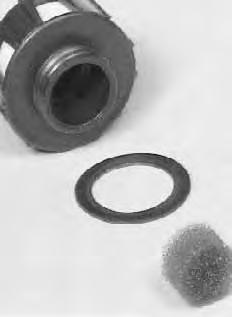
Clean the filter (Item 2) [B] in the breather cap.
Make sure the baffle washer (Item 3) [B] is installed in the hydraulic reservoir.

Replace the breather cap at regular intervals. (See the SERVICE SCHEDULE Page 37.)
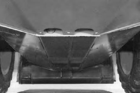
Spark Arrestor Muffler
See the SERVICE SCHEDULE Page 37 for service interval for cleaning the spark arrestor muffler.

Do not operate the loader with a defective exhaust system.
This loader is factory equipped with a U.S.D.A. Forestry Service approved spark arrestor muffler. It is necessary to do maintenance on this spark arrestor muffler to keep it in working condition. The spark arrestor muffler must be serviced by dumping the spark chamber every 100 hours of operation.
If this machine is operated on flammable forest, brush or grass covered land, it must be equipped with a spark arrestor attached to the exhaust system and maintained in working order. Failure to do so will be in violation of California State Law, Section 4442 PRC.
Make reference to local laws and regulations for spark arrestor requirements.
I–2022–0595
Stop the engine. Open the rear door and rear grill. Remove the plug (Item 1) [A] from the bottom of the muffler.
When an engine is running in an enclosed area, fresh air must be added to avoid concentration of exhaust fumes. If the engine is stationary, vent the exhaust outside. Exhaust fumes contain odorless, invisible gases which can kill without warning.
W–2050–1285
Stop engine and allow the muffler to cool before cleaning the spark chamber. Wear safety glasses or goggles. Failure to obey can cause serious injury.
W–2011–1285
Never use machine in atmosphere with explosive dust or gases or where exhaust can contact flammable material. Failure to obey warnings can cause injury or death.
W–2068–1285
When the engine is running during service, the steering levers must be in neutral and the parking brake engaged. Failure to do so can cause injury or death.
W–2006–0284
Start the engine and run for about 10 seconds while a second person, wearing safety glasses, holds a piece of wood over the outlet of the muffler.
This will force contaminants out through the cleanout hole.
Stop the engine.
Install and tighten the plug.
Lower the rear grill and close the rear door.
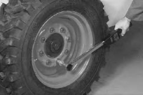
Tire Maintenance
Wheel Nuts
See the SERVICE SCHEDULE Page 37 for the service interval to check the wheel nuts. The correct torque is 105–115 ft.–lbs. (142–156 Nm) torque [A].
Tire Rotation
Check the tires regularly for wear, damage and pressure. Rear tires usually wear faster than front tires. To keep tire wear even, move the front tires to the rear and rear tires to the front [B].
It is important to keep the same size tires on each side of the loader. If different sizes are used, each tire will be turning at a different rate and cause excessive wear. The tread bars of all the tires must face the same direction.
Recommended tire pressure must be maintained to avoid excessive tire wear and loss of stability and handling capability. Check for the correct pressure before operating the loader.
Tire Mounting
Tires are to be repaired only by an authorized person using the proper procedures and safety equipment. Tires and rims must always be checked for correct size before mounting. Check rim and tire bead for damage.
The rim flange must be cleaned and free of rust. The tire bead and rim flange must be lubricated with a rubber lubricant before mounting the tire, avoid excessive pressure which can rupture the tire and cause serious injury or death. During inflation of the tire, check the tire pressure frequently to avoid over inflation.
FINAL DRIVE TRANSMISSION (CHAINCASE)
Checking And Adding Oil
The chaincase contains the final drive sprockets and chains. Use the same type of oil as the hydraulic/ hydrostatic system. (See SPECIFICATIONS Page 87.)
Stop the loader on a level surface. Stop the engine. Remove the plug (Item 1) [A]
If oil can be reached with the tipof the your finger through the hole, the oil level is correct.
Add oil as needed through the check plug hole until the oil flows from the hole.
Install and tighten the plug.
Removing Oil From The Chaincase
Remove the cover (Item 1) [B] which is installed over the drain plug at the bottom rear of the chaincase.


Remove the drain plug (Item 1) [C] and drain the oil into a container.
Check the drain plug and replace as necessary.
NOTE:When installing the drain plug into the chaincase, always use a NEW drain plug gasket.
Fan Gearbox

See the SERVICE SCHEDULE Page 37 for the correct service interval.
Checking And Maintaining
Raise the operator cab. (See Raising the Operator Cab Page 40.)
Remove the plug (Item 1) [A]
Lubricant level is correct if it flows from the check plug hole.
If the level is low, add SAE 90W gear lube through the check plug hole until the lubricant flows from the hole. Install and tighten the plug.
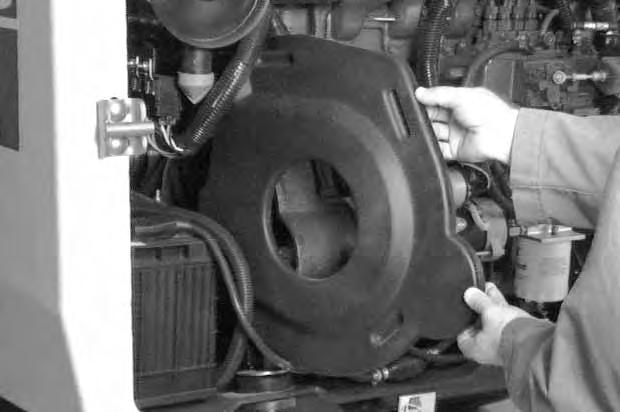
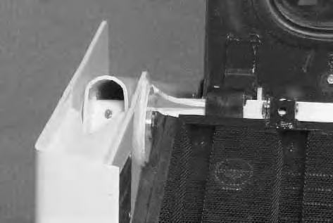
Drive Belt
Adjusting The Drive Belt 20. Stop the engine.
Open the rear door.
Disconnect the negative (–) cable from the battery. Remove the belt shield fasteners (Item 1) [A]
Remove the belt shield. [B]
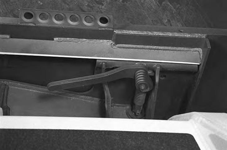
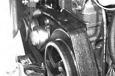
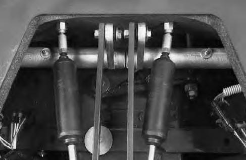
The belt tensioner is located between the flywheel and pump pulley.
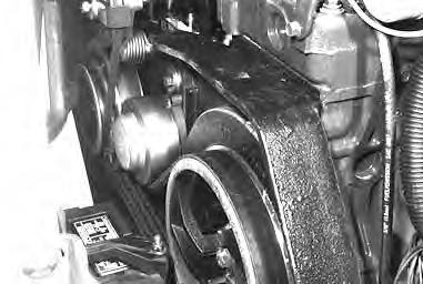

Loosen the bolt (Item 1) [C] on the spring loaded drive idler.
NOTE:The pointer will be at the 1 o’clock position (Item 2) [C] when the belt tensioner is not under spring tension.
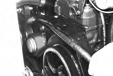
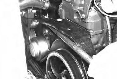
Push the idler pulley against the belt, using apry bar [D]. The pointer will be at the 3 o’clock position (Item 1) [D] when the idler pulley is against the stop (maximum movement).
DRIVE BELT (Cont’d)
Adjusting The Drive Belt (Cont’d)
Raise the idler assembly slightly so that the pulley is operating on spring tension and not against the stop.
NOTE:Do not set the idler against the travel stop in the 3 o’clock position.
Tighten the mounting bolt (Item 1) [A] to 25–28 ft.lbs. (34–38 Nm) torque.
Run the engine for a few minutes.
Stop the engine and recheck the pointer position.
Readjust if necessary.
Readjust whenever the pointer reaches the 1 o’clock position.
Install the belt shield using the fasteners.
Reconnect the negative (–) battery cable.
Close the rear door.
Replacing The Drive Belt
Stop the engine. Open the rear door.
Raise the operator cab. (See Raising The Operator Cab Page 40.)
Remove the negative (–) cable from the battery. (The battery may be removed for additional working clearance.) (See Removing The Battery Page 59.)
Remove the shield fasteners and the belt shield [B].
Remove the fan drive belt (Item 1) [C].
The belt tensioner is located between the flywheel and pump pulley.

Loosen and remove the bolt (Item 2) [C] from the belt tensioner.
Remove the belt tensioner assembly.
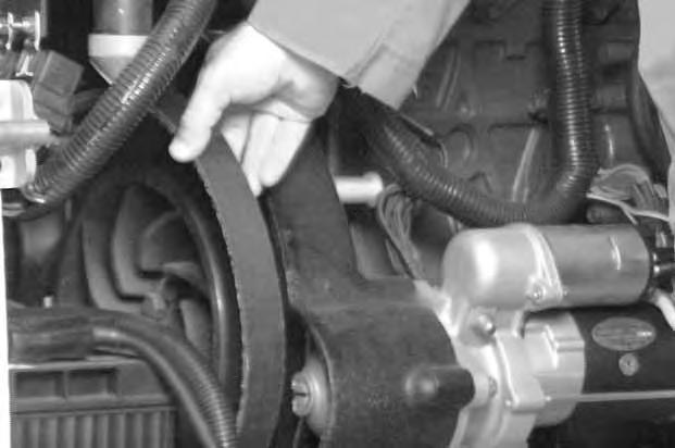
Remove the drive belt from the pump pulley and flywheel. Remove the drive belt from the loader [D]
Install the new drive belt. Install the belt tensioner assembly.
Install the fan drive belt.
Adjust the drive belt. (See Adjusting The Drive Belt Page 68.)
Reinstall previously removed components and connect the negative (–) cable to the battery.
LUBRICATING THE BOBCAT LOADER 21.
Lubricate the loader as specified in the SERVICE SCHEDULE Page 37 for the best performance of the loader.
Record the operating hours each time you lubricate the Bobcat loader.
Always use a good quality lithium based multi–purpose grease. Apply lubricant until extra grease shows.

Lubricate the following locations on the loader:
LUBRICATING THE BOBCAT LOADER (Cont’d)

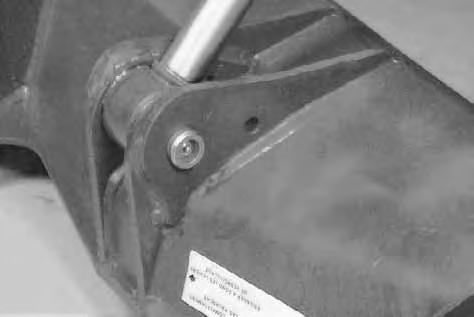
PIVOT PINS
All lift arm and cylinder pivots have a large pin held in position with a retainer bolt and lock nut (Item 1) [D].
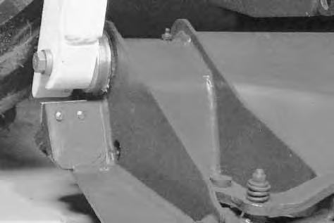
Check that the lock nuts are tightened to 18–20 ft.–lbs. (24–27 Nm) torque.
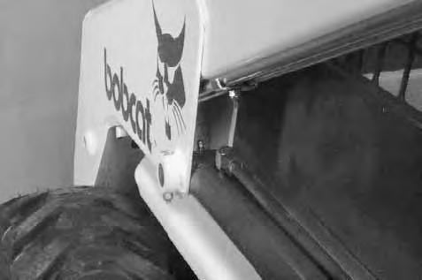
BOB–TACH
Inspection and Maintenance
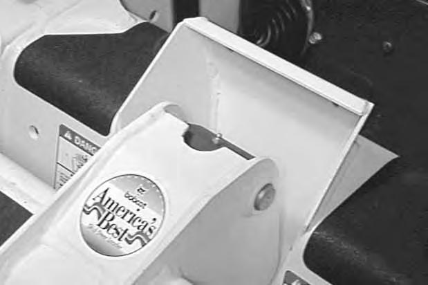
Move the Bob–Tach levers to engage the wedges [A]. The levers and wedges must move freely.
The wedges must extend through the holes in the attachment mounting frame (Item 1) [A]
Bob–Tach wedges must extend through the holes in attachment. Levers must be fully down and locked. Failure to secure wedges can allow attachment to come off and cause injury or death.

W–2102–0588
The spring loaded wedge (Item 1) [A] must contact the lower edge of the hole in the attachment(Item 1) [B] and [C].
If the wedge does not contact the lower edge of the hole [B] and [C], the attachment will be loose and can come off the Bob–Tach.
Inspect the mounting frame on the attachment and the Bob–Tach, linkages and wedges for excessive wear or damage [D]. Replace any parts that are damaged, bent, or missing. Keep all fasteners tight.
Look for cracked welds. Contact your Bobcat dealer for repair or replacement parts.
Lubricate the wedges (SeeSERVICE SCHEDULE, Page 37 and LUBRICATION OF THE BOBCAT LOADER, Page 70).