8 minute read
STARTING THE ENGINE (Cont’d)


Normal Starting
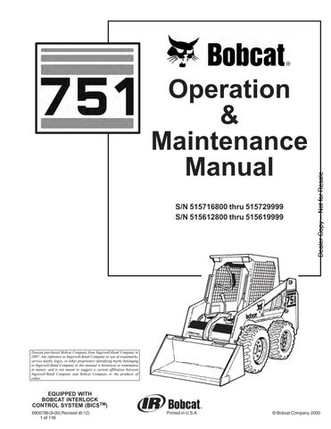
Adjust the seat position, fasten the seat belt and lower the seat bar [A]
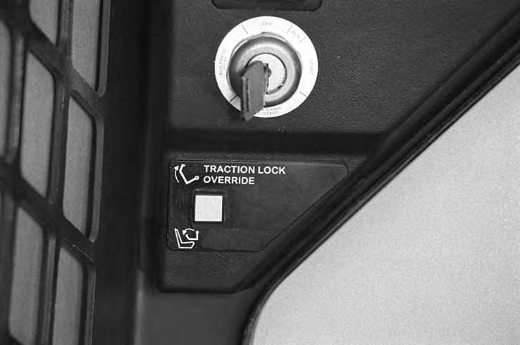
Put the foot pedals (or hand controls) and steering levers in NEUTRAL POSITION (center) (Item 1) [B]
Set the engine speed control to the 1/2 SPEED position (Item 2) [B]
Turn the key switch to the ON POSITION. The engine and transmission warning lights will be ON when the key switch is on and the engine is stopped (Item 3) [B]
Turn the key switch to START POSITION (Item 4) [B] and release it when the engine starts.
Advanced Hand Controls Only: Make sure both hand controls are in neutral before starting the engine. Do not move the Advanced Hand Control levers from the neutral position when turning the key ON.
If either hand control is moved: a. – The neutral position for the hydraulic valve spool and hand control may not be correctly calibrated. This can result in movement of the lift or tilt hydraulic cylinders when the hand control lever is returned to the neutral position after start– up.
OR b. – The hydraulics will not operate (corresponding diagnostic lights on the left handle will blink).
If either condition occurs, turn the key OFF. Put the controls in neutral position and re–start the engine.
Do not engage the starter for longer than 15 seconds at a time. Longer use can damage the starter by overheating. Cool the starter for one minute between uses.
When you release the key, it will return to the RUN POSITION (Item 5) [B]
STOP THE ENGINE IF THE WARNING LIGHTS DO NOT GO OFF.
STARTING THE ENGINE (Cont’d)
Cold Temperature Starting
(See also Normal Starting)
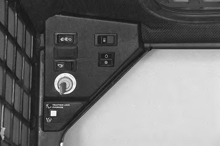
Turn the key switch to the RUN POSITION. Hold the preheat switch (Item 1)[A] the time indicated on the preheat decal [B], in the operators cab.
Follow the steps under Normal Starting and repeat the Preheat procedure until the engine starts.
If the temperature is below 32 °F. (0°C.), perform the following to make starting the engine easier:
• Replace the engine oil with the correct type and viscosity for the anticipated starting temperature. (See ENGINE LUBRICATION SYSTEM Page 52.)
• Make sure the battery is fully charged.
• Install an engine heater, available from your Bobcat loader dealer.
Warming the Hydraulic/Hydrostatic System
Let the engine run for a minimum of 5 minutes to warm the engine and hydrostatic transmission fluid before operating the loader. If the warning light comes ON when operating loader (cold), more warm up time is needed.
When the temperature is below –20°F. (–30°C.), hydrostatic oil must be warmed before starting. The hydrostatic system will not get enough oil at low temperatures and will be damaged. Park the machine in an area where the temperature will be above 0°F. (–18°C.) if possible.
I–2007–1285
Stopping The Engine
Pull the engine speed control fully backward to decrease the engine speed. Turn the key switch to the OFF POSITION [C].
Attachments And Buckets
NOTE:Warranty is void if non–approved attachments are used on the Bobcat loader.
Never use attachments or buckets which are not approved by Bobcat Company. Buckets and attachments for safe loads of specified densities are approved for each model. Unapproved attachments can cause injury or death.
The dealer can identify, for each model loader, the attachments and buckets approved by BobcatCompany. The buckets and attachments are approved for rated operating capacity and for secure fastening to the Bob–Tach.
The rated operating capacity for this loader is shown on a label in the operator cab. (SeeSPECIFICATIONS Page 87.) It is determined by using a standard dirt bucket, and material of normal density, such as dirt or dry gravel. If longer buckets are used, the load center moves forward and reduces the rated operating capacity. If very dense material is loaded, the volume must be reduced.
Exceeding the rated operatingcapacity [A] can cause the following problems:
1.Steering the loader may be difficult.
2.Tires will wear faster.
3.There will be a loss of stability.
4.The life of the Bobcat loader will be reduced.
Use the correct size bucket for the type and density of material being handled. For safe handling of materials and avoiding machine damage, the attachment (or bucket) should handle a full load without going over the rated operating capacity for the loader. Partial loads make steering more difficult.
Maximum load to be carried when using a pallet fork are shown in figure [B]. See your Bobcat dealer for more information about pallet forks and other available attachments.
INJURY OR DEATH
W–2053–0887 AVOID
WEIGHT OF LOADS LBS. (KG)
(Without counterweights)
ATTACHMENTS AND BUCKETS (Cont’d)
Installing The Bucket Or Attachment
The loader is equipped with the Bob–Tach system. The Bob–Tach is used for fast changing of buckets and attachments. See the Attachment Operation & Maintenance Manual to install other attachments.
Pull the Bob–Tach levers all the way up (Item 1) [A]
Enter the loader.
Fasten the seat belt, lower the seat bar, start the engine and press the green PRESS TO OPERATE Button.
Release the parking brake.
Lower the lift arms and tilt the Bob–Tach forward.
Drive the loader forward until the top edge of the Bob–Tach is completely under the top flange of the bucket [A] (or other attachments).
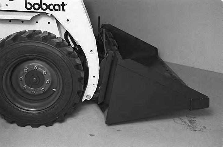
Be sure the Bob–Tach levers do not hit the bucket.
Tilt the Bob–Tach backward until the cutting edge of the bucket (or other attachment) is slightly off the ground [B]
Stop the engine and exit the loader.
Before you leave the operator’s seat:
• Lower the lift arms, put the attachment flat on the ground.
• Stop the engine.
• Engage the parking brake.
• Raise seat bar.
• (Foot Pedal Controls) Move pedals until both lock.
• (Mechanical Hand Controls) Move the hand controls until both lock.
The seat bar system must lock the lift and tilt controls in neutral when the seat bar is up. Service the system if hand controls do not lock correctly.
• (Advanced Hand Controls) Move the hand controls to the NEUTRAL POSITION to make sure that both lift and tilt functions are deactivated.
The seat bar system must deactivate the lift and tilt control functions when the seat bar is up. Service the system if hand controls do not deactivate.
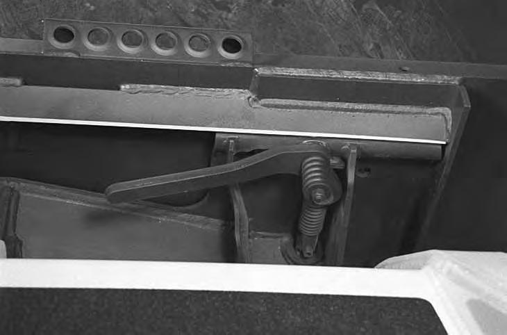
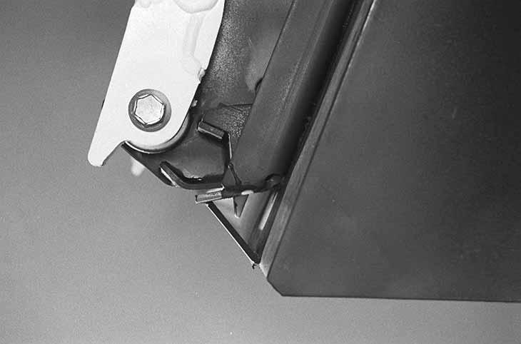
Push down on the Bob–Tach levers until they are fully engaged in the locked position [C]
The levers will contact the frame as shown (Item 1) [C] when locked.
If the levers do not engage in the locked position, see your Bobcat loader dealer for maintenance.
Bob–Tach levers have spring tension. Hold lever tightly and release slowly. Failure to obey warning can cause injury.
ATTACHMENTS AND BUCKETS (Cont’d)
The wedges (Item 1) [A] must extend through the holes (Item 1) [B] in the mounting frame of the bucket (or attachment), securely fastening the bucket to the Bob–Tach. The wedge is shown extending through the hole in the bucket [A]
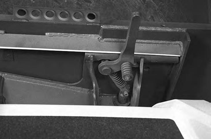
Bob–Tach wedges must extend through the holes in attachment. Lever(s) must be fully down and locked. Failure to secure wedges can allow attachment to come off and cause injury or death.

Removing The Bucket Or Attachment
Put the attachment flat on the ground and lower or close the hydraulic equipment. If the attachment is hydraulically controlled (ie: combination bucket, backhoe, etc.), stop the engine and relieve hydraulic pressure in the auxiliary circuit (See Relieving Hydraulic Pressure, Page 15).
Raise the seat bar, unfasten the seat belt, set theparking brake and exit the loader.
Pull the Bob–Tach levers [C] all the way up.
Disconnect the hydraulic hoses, if necessary. Enter the loader.
Fasten the seat belt, lower the seat bar, start the engine and press the green PRESS TO OPERATE Button.
Release the parking brake.
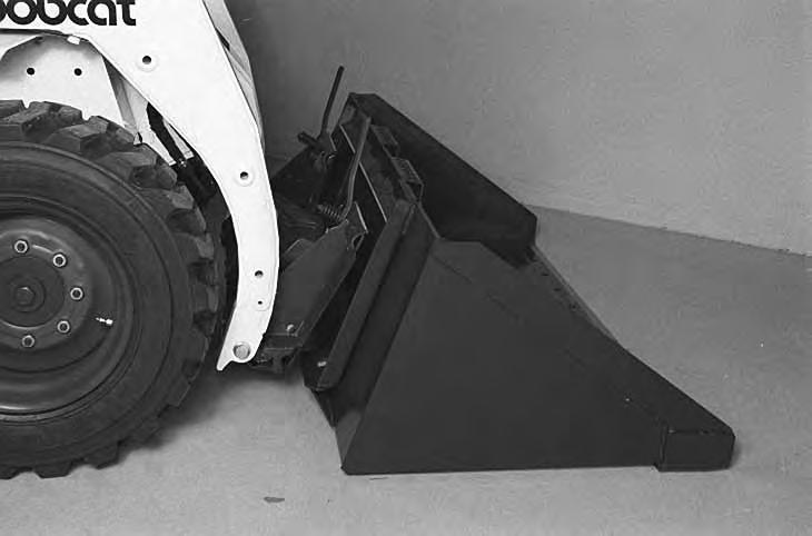
Lower the lift arms and tilt the Bob–Tach forward.
Move the loader backward, away from the bucket or attachment [D]
Operating Procedures
When operating on a public road or highway, always follow local regulations. For example: Slow Moving Vehicle Sign or direction signals may be required. Always warm the engine and hydrostatic system before operating the loader.
Machines warmed up with moderate engine speed and light load have longer life.
I–2015–0284
Operate the loader with the engine at full speed for maximum horsepower. Move the steering levers only a small amount to operate the loader slowly.
New operators must operate the loader in an open area without bystanders. Operate the controls until the loader can be handled at an efficient and safe rate for all conditions of the work area.
With a full bucket, go up or downthe slope with the heavy end toward the top of the slope [A] & [B]
With empty bucket, go down or up the slope with the heavy end toward the top of the slope [C] & [D]
• Keep the lift arms as low as possible.
• Do not travel or turn with the lift arms up.
• Turn on level ground.
• Go up and down slopes, not across them.
• Keep the heavy end of the machine uphill.
• Do not overload the machine.
Failure to obey warnings can cause the machine to tip or roll over and cause injury or death.
W–2018–1187
Raise the bucket only high enough to avoid obstructions on rough ground.
D
OPERATING PROCEDURES (FOOT PEDALS)
Filling the Bucket
Push down on the top of the lift pedal until the lift arms are all the way down.
Push the top of the tilt pedal to put the cutting edge of the bucket on the ground [A]
Drive slowly forward into the material.
Push the bottom of the tilt pedal to raise the front of the bucket [B].
Drive backward away from the material.
Load, unload and turn on flat level ground. Do not exceed rated operating capacity shown on sign (decal) in cab. Failure to obey warnings can cause the machine to tip or roll over and cause injury or death.
W–2056–1187
Emptying the Bucket
Push down on the bottom of the lift pedal to raise the lift arms [C]. Push the top of the tilt pedal while raising the lift arms to level the bucket or attachment and help prevent material from falling off the back of the bucket or attachment.
Drive forward slowly until the bucket is over the top of the truck box or bin.
Push the top of the tilt pedal until the bucket is empty[C] If all the material is near the side of thetruck or bin, push it to the other side with the bucket.
Never dump over an obstruction, such as a post, that can enter the operator cab. The machine could tip forward and cause injury or death.
W–2057–0694
OPERATING PROCEDURES (FOOT PEDALS) (Cont’d)
Digging Into the Ground
Put the lift arms all the way down.
Push the top of the tilt pedal until the cutting edge of the bucket is on the ground.
Drive forward slowly and continue to tilt the bucket down until it enters the ground [A]
Push the bottom of the tilt pedal a small amount to increase traction and keep an even digging depth. Continue to drive forward until the bucket is full.
When the ground is hard, raise and lower the cutting edge of the bucket with the tilt pedal while driving forward slowly.
Push the bottom of the tilt pedal to tiltthe bucket backward as far as it will go when the bucket is full [B]
Leveling the Ground (Using Lift Arms in Float Position)
Push the top (toe) of the lift pedal all the way forwarduntil the pedal is in the locked position to put the lift arms in a float position [C]
Push the tilt pedal to change the position of the cutting edge on the bucket.
With the bucket tilted farther forward, there is more force on the cutting edge and more loose material can be moved.
Never drive forward when the hydraulic control for lift arms is in float position.
I–2005–1285
Drive backward to level loose material.
Push the bottom (heel) of the lift pedal tounlock from the float position.