20 minute read
BEFORE OPERATING THE BOBCAT LOADER


Safety Alert Symbol
This symbol with a warning statement means: “Warning, be alert! Your safety is involved!” Carefully read the message that follows.
The Bobcat loader and attachment must be in good operating condition before use.
Check all of the items on the Bobcat Service Schedule Decal under the 8–10 hour column or as shown in this Manual.
SAFE OPERATION NEEDS A QUALIFIED OPERATOR *
A QUALIFIED OPERATOR MUST DO THE FOLLOWING:
• UNDERSTAND THE WRITTEN INSTRUCTIONS, RULES AND REGULATIONS
• The written instructions from Bobcat Company include the Delivery Report, Operation & Maintenance Manual, Operator’s Handbook, Safety Manual and machine signs (decals).
• Check the rules and regulations at your location. The rules may include an employer’s work safety requirements. Regulations may apply to local driving requirements or use of a Slow MovingVehicle (SMV) emblem. Regulations may identify a hazard such as a utility line.
• HAVE TRAINING WITH ACTUAL OPERATION
Operator must have instructions before running the machine. Untrained operators can cause injury or death.
W–2001–1285
This notice identifies procedures which must be followed to avoid damage to the machine.
I–2019–0284
Warnings on the machine and in the manuals are for your safety. Failure to obey warnings can cause injury or death.
W–2044–1285
• Operator training must consist of a demonstration and verbal instruction. This training is given by your Bobcat dealer before the product is delivered.
• The new operator must start in an area without bystanders anduse all the controls until he can operate the machine and attachment safely under all conditions of the work area. Always fasten seat belt before operating.
• Operator Training Courses are available from your Bobcat dealer in English and Spanish. They provide information for safe and efficient equipment operation. Safety videos are also available.
• Service Safety Training Courses are available from your Bobcat dealer. They provide information for safe and correct service procedures.
• KNOW THE WORK CONDITIONS
• Know the weight of the materials being handled. Avoid exceeding the Rated Operating Capacity of the machine. Material which is very dense will be heavier than the same volume of less dense material. Reduce the size of load if handling dense material.
• The operator must know any prohibited uses or work areas, for example, he needs to know about excessive slopes.
• Know the location of any underground lines. Call local utilities or the TOLL FREE phone number found in the SAFETY INSTRUCTIONS Section of this manual.
• Wear tight fitting clothing. Always wear safety glasses when doing maintenance or service. Safety glasses, hearing protection or special applications kit are required for some work.See your dealer about Bobcat Safety equipment. * For an operator be qualified, he must not use drugs or alcoholic drinks which impair his alertness or coordination while working. An operator who is taking prescription drugs must get medical advice to determine if he can safely operate a machine.
SI02–0400
Fire Prevention
The machines and some attachments have components that are at high temperatures under normal operating conditions. The primary source of high temperatures is the engine and exhaust system. The electrical system, if damaged or incorrectly maintained, can be a source of arcs or sparks.
Flammable debris (leaves, straw, etc.) must be removed regularly. If flammable debris is allowed to accumulate, it can cause a fire hazard. Clean often to avoid this accumulation. Flammable debris in the engine compartment is a potential fire hazard.
The spark arrestor exhaust system (if equipped) is designed to control the emission of hot particles from the engine and exhaust system, but the muffler and the exhaust gases are still hot.
• Do not use the machine where exhaust, arcs, sparks or hot components can contact flammable material, explosive dust or gases.
• The operator cab, engine compartment and engine cooling system must be inspected every day and cleaned if necessary to prevent fire hazards and overheating.
• Check all electrical wiring and connections for damage. Keep the battery terminals clean andtight. Repair or replace any damaged part.
• Check fuel and hydraulic tubes, hoses and fittings for damage and leakage. Never use open flame or bare skin to check for leaks. Tighten or replace any parts that show leakage. Always clean fluid spills. Do not use gasoline or diesel fuel for cleaning parts. Use commercial nonflammable solvents.
• Do not use ether or starting fluids on any engine which has glow plugs. These starting aids can cause explosion and injure you or bystanders.
• Always clean the machine, disconnect the battery, and disconnect the wiring from the electronic controllers before welding. Cover rubber hoses, battery and all other flammable parts. Keep a fire extinguisher near the machine when welding. Have good ventilation when grinding or welding painted parts. Wear dust mask when grinding painted parts. Toxic dust or gas can be produced.
• Stop the engine and let it cool before adding fuel. No smoking!
• Use the procedure in the Operation & Maintenance Manual for connecting the battery and for jump starting.
• Use the procedure in the Operation & Maintenance Manual for cleaning the spark arrestor muffler (if equipped).
• Know where fire extinguishers and first aid kits are located and howto use them. Fire extinguishers are available from your Bobcat dealer.
MACHINE SIGNS (DECALS)
Follow the instructions on all the Machine Signs (Decals) that are on the loader. Replace any damaged machine signs and be sure they are in the correct locations. Machine signs are available from your Bobcat loader dealer.
MACHINE SIGNS (DECALS) (Cont’d)

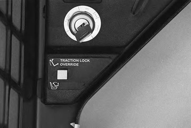
Front Panel [A]
1. TRACTION LOCK OVERRIDE BUTTON (Functions Only When Seat Bar Is Raised) – Allows you to use the steering levers to move the loader forward or backward when using the backhoe attachment or for loader service. (See Page 5.)
2. PRESS TO OPERATE BUTTON (Functions Only When The Seat Bar Is Down) – Activates BICS™ System when the Seat Bar is down and operator is seated in the operating position.
3. KEY SWITCH – For starting & stopping the engine.
4. TRANSMISSION WARNING LIGHT – Low transmission charge pressure, hydraulic filter needs replacement or high fluid temperature. Stop the engine if the light comes ON.
5. ENGINE WARNING LIGHT – Low engine oil pressure or high coolant temperature. Stop the engine if the light comes ON.
6. LIGHT SWITCH (Opt. / FA) – Controls the available work and travel lights.
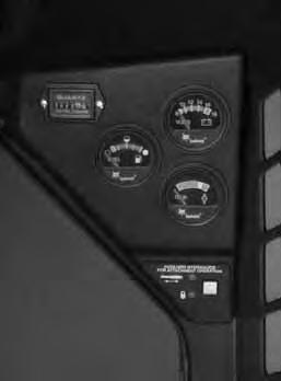
7. BUCKET LEVEL SWITCH (Opt. / FA) – Controls the ON / OFF function of the available Bucket Position Valve.
8. PREHEAT BUTTON – For preheating the engine (glow plugs) before starting the engine.
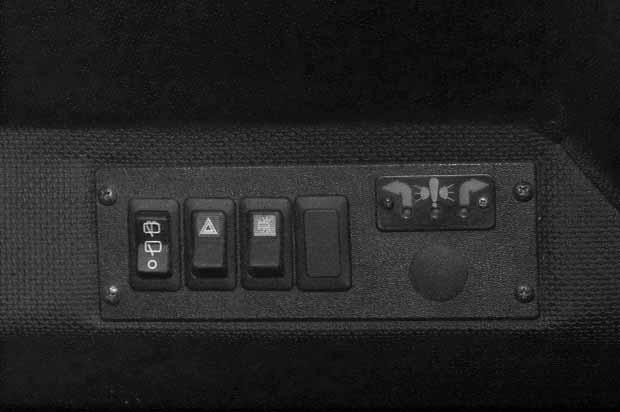
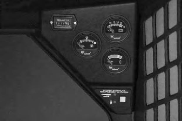
9. HOURMETER – Records the total operating hours of the loader.
10. FUEL GAUGE – Shows the amount of fuel in the fuel tank.
11. VOLTMETER – Shows the condition of the battery and the rate of charge.
12. ENGINE TEMPERATURE GAUGE – Shows the engine coolant temperature.
13. AUXILIARY HYDRAULICS SWITCH (Opt. / FA) – For engaging the available Auxiliary Hydraulics (front or rear).
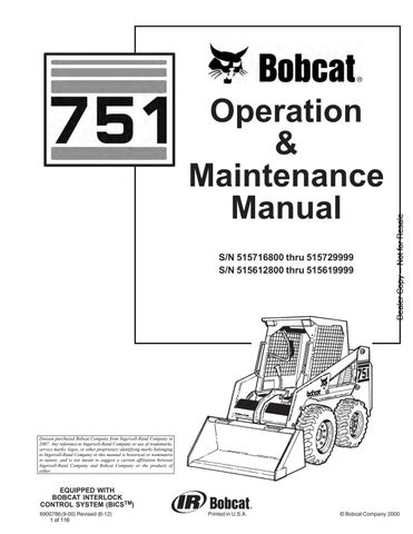
Side Console* [B]
1. REAR WIPER / WASHER (FA) – Controls operation of the available rear window wiper and washer.
2. HAZARD SWITCH / HAZARD INDICATORS (Opt. / FA) – Controls the available hazard lights. (Hazard Lights is a separate available accessory.) Both panel indicators blink for hazard condition when the hazard switch is ON. A red light indicates fuse out for taillights, headlights, work lights, etc.
3. BEACON OR STROBE SWITCH (Opt. / FA) –Controls the available flashing beacon or strobe light.
* Can be installed if you have a Deluxe Cab or a Cab Enclosure installed Opt . – Factory Installed Opt ion
FA – F ield Installed Accessory – See your Bobcatloader dealer about available Field Accessories.
BOBCAT INTERLOCK CONTROL SYSTEM (BICS™)
The Bobcat Interlock Control System (BICS ™) requires the operator to be seated in the operating position with the Seat Bar fully lowered and the green PRESS TO OPERATE Button [B] activated before the lift, tilt and traction functions can be operated. The Seat Belt must be fastened anytime you operate the loader.
NOTE:Press the green PRESS TO OPERATE Button (Item 1) [B] again if Seat Bar is raised and lowered or key is turned OFF.
Avoid Injury Or Death
The Bobcat Interlock Control System (BICS) must deactivate the lift, tilt and traction drive functions. If it does not, contact your dealer for service. DO NOT modify the system.
W–2151–0394
The lift, tilt and traction drive functions are interlockedwith the Seat Bar.
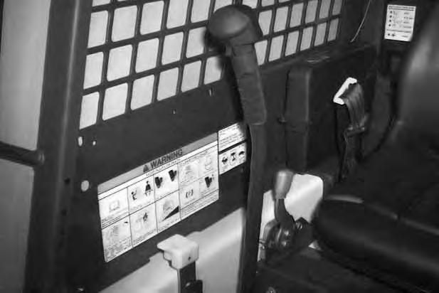
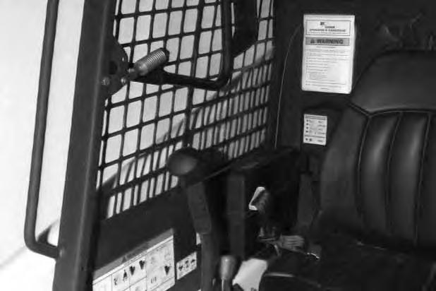
The BICS controller is located inside the cab; behind and to the right of the operator’s seat [A]
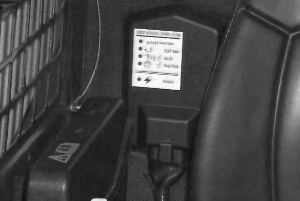
There are five green lights on the BICS controller and all lights must be ON to operate the loader. The light functions are as follows [A]:
1. SYSTEM ACTIVATED – ON when the green PRESS TO OPERATE Button is activated.
2. SEAT BAR – ON when the seat bar is in down position.
3. VALVE – ON when lift and tilt hydraulic functions can be used.
4. TRACTION – ON when loader can be moved forward or backward.
5. POWER – ON when the controller is operating correctly.
NOTE: If any of the lights are off or blinking, see SYSTEMS ANALYSIS, BICS Troubleshooting Chart, Page 75; or, see BICS Inspection and Maintenance Instructions, Page 46.
BOBCAT INTERLOCK CONTROL SYSTEM (BICS™) (Cont’d)
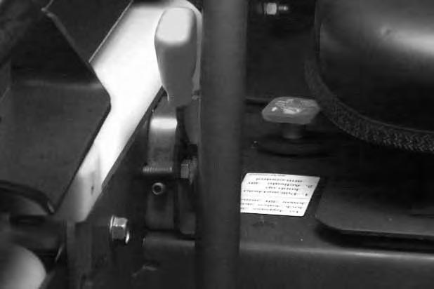
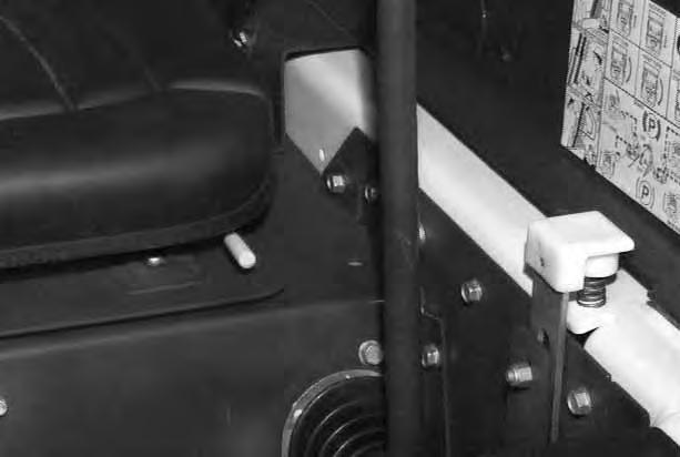
Lift Arm By–Pass Control
Use the lift arm by–pass control knob (Item 1)[A] to lower the lift arms if the lift arms can not be lowered during normal operation.
With the operator in the seat, seat belt fastened and the seat bar fully lowered, turn the lift arm by–pass control knob (Item 1) [A] clockwise 1/4 turn. Then, pull up and hold the lift arm by–pass control until the lift arms slowly lower.
Traction Lock Override
6.
(Functions Only When The Seat Bar Is Raised)
There is a traction lock override button (Item 1)[B] on the left hand instrument panel which will allow you to use the steering levers to move the loader forward & backward when using the backhoe attachment or for loaderservice.

Press the button once to unlock traction drive (green traction light on BICS controller will be ON).
Press the button a second time to lock the traction drive (green traction light on BICS controller will be OFF).
NOTE:The Traction Lock Override button will unlock the traction drive when the operator is NOT in the seat and the seat bar is raised.
The Traction Lock Override button will function if brake pedal is in the engaged or disengaged position.
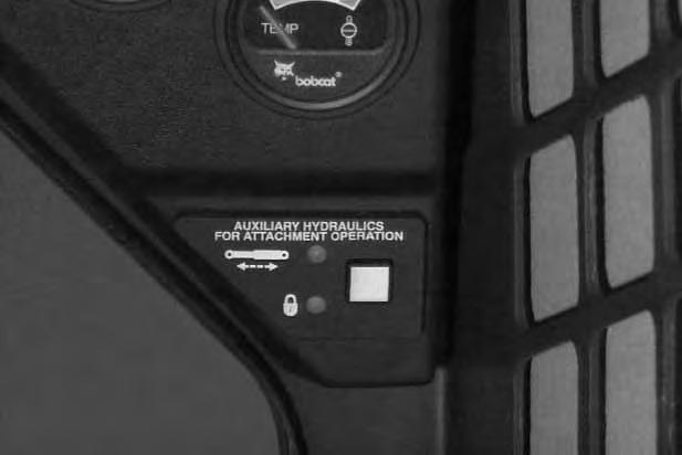
Auxiliary Hydraulic System
When the operator is seated and raises the seat bar, the Auxiliary Hydraulic System will deactivate. Press the Auxiliary Hydraulics Switch (Item 1) [C] to reselect operating mode.(See Auxiliary Hydraulics Page 13.)
Engine Speed Control
The speed control lever (Item 1) [A] is at the right side of the operator’s seat. Change the engine speed by moving the lever forward to increase the engine RPM and backward to decrease the engine RPM.
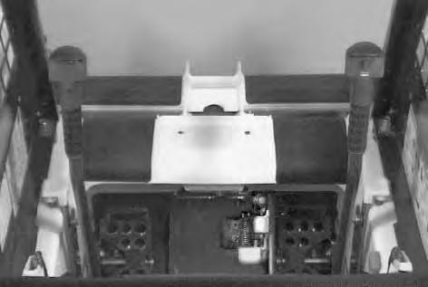
Parking Brake
Engage the parking brake by pushing down on the top of the pedal [B]. The traction drive system will be locked. (See Traction Lock Override, Page 5.)
Release the parking brake by pushing down on the bottom of the pedal [C].
NOTE:If the loader will not move when operator is in the operating position with brake pedal released or when Traction Lock Override button is pushed, move the steering levers either forward or backward a small amount to unlock the traction drive.
Avoid Injury Or Death
When operating the machine:
• Keep the seat belt fastened snugly.
• The seat bar must be lowered.
• Keep your feet on the pedal controls or footrests.
Failure to obey warnings can cause injury or death.
W–2261–0397
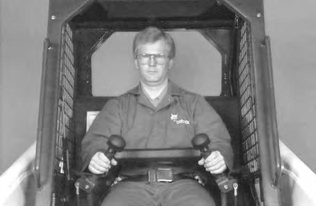
The steering levers (Item 1) [A] are on the right and left side in front of the seat.
Move the levers smoothly. Avoid sudden starting and stopping.
The steering levers control forward and reverse travel of the loader [B]
Forward Travel – Push both levers forward.
Reverse Travel – Pull both levers backward.
Normal Turning – Move one lever farther forward than the other.
Fast Turning – Push one lever forward and pull the other lever backward.
For slow travel speed, push the steering levers forward only a small amount.
To increase travel speed, push both levers farther forward.
For maximum pushing force, push the levers forward only a small amount with the engine at full RPM.
Stopping The Bobcat Loader
When the steering levers are moved to the NEUTRAL POSITION, the hydrostatic transmission will act as a service brake to stop the loader.
Reverse
RIGHT TURN 751 Bobcat Loader Operation & Maintenance Manual 7
Left Turn
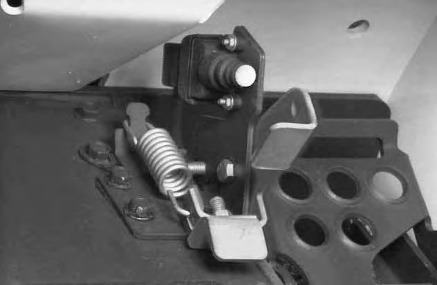
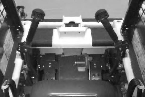
SEAT BAR RESTRAINT SYSTEM (FOOT PEDALS)
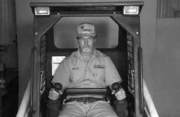
The seat bar restraint system has a pivoting , spring assist seat bar (Item 1) [A] with arm rests and has spring loaded interlocks for the lift and tilt control pedals.
The operator controls the use of the seat bar. The seat bar in the down position helps to keep the operator in the seat.
The interlocks require the operator to lower the seat bar in order to operate the foot pedals.
When the seat bar is up, the lift and tilt foot pedals are locked when returned to the NEUTRAL POSITION.
Avoid Injury Or Death
When operating the machine:
• Keep the seat belt fastened snugly.
• The seat bar must be lowered.
• Keep your feet on the pedal controls or footrests.
W–2261–0397
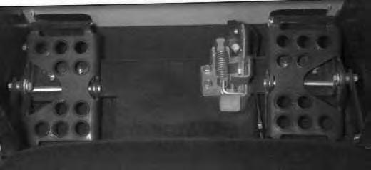
The spring loaded interlocks (Item 1) [B] control the locking and unlocking functions of the foot pedals.
The interlocks (Item 1) [B] require the operator to lower the seat bar (Item 2) [B] which allows the operator to move the foot pedals to control the lift and tilt functions.
When the seat bar is lowered, it pushes the interlock (Item 1) [B] down on both sides, releasing the pedal linkages (Item 3) [B] from the interlocks.
The foot pedals will pivot in both directions when the interlock is down.
Before you leave the operator’s seat:
• Lower the lift arms, put the attachment flat on the ground.
• Stop the engine.
• Engage the parking brake.
• Raise seat bar.
• (Foot Pedal Controls) Move pedals until both lock.
W–2328–0798
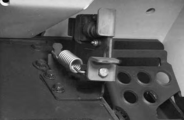
When the seat bar is raised, spring forces raise the interlocks [C].
The foot pedals will not pivot when the interlock is up. Refer to Seat Bar Restraint System Inspection & Maintenance Page 43.
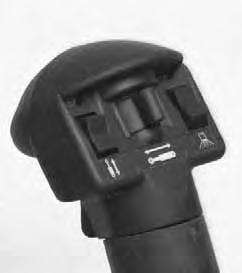
SEAT BAR RESTRAINT SYSTEM (MECHANICAL HAND CONTROLS)
The seat bar restraint system has a pivoting seat bar (Item 1) [A] with arm rests and has spring loaded interlocks for the lift and tilt control functions.
The operator controls the use of the seat bar. The seat bar in the down position helps to keep the operator in the seat.
The interlocks require the operator to lower the seat bar in order to operate the hand controls.
When the seat bar is up, the lift and tilt control functions are locked when returned to the NEUTRAL POSITION.
Avoid Injury Or Death
When operating the machine:
• Keep the seat belt fastened snugly.
• The seat bar must be lowered.
• Keep your feet on the footrests. W–2179–0694
The spring loaded interlocks (Item 1) [B] control the locking and unlocking functions of the hand controls.
The interlocks (Item 1) [B] require the operator to lower the seat bar (Item 2) [B] which allows the operator to move the hand controls to control the lift and tilt functions.
When the seat bar is lowered, it pushes the interlock (Item 1) [B] down on both sides, releasing the hand control linkages (Item 3) [B] from the interlocks.
The hand controls will pivot in both directions when the interlock is down.
Before you leave the operator’s seat:
• Lower the lift arms, put the attachment flat on the ground.
• Stop the engine.
• Engage the parking brake.
• Raise seat bar.
• (Mechanical Hand Controls) Move the hand controls until both lock. The seat bar system must lock the lift and tilt controls in neutral when the seat bar is up. Service the system if hand controls do not lock correctly.
W–2322–0698
When the seat bar is raised, spring forces raise the interlocks [C]
The hand controls will not function when the interlock is up.
Refer to SEAT BAR RESTRAINT SYSTEM Inspection And Maintaining The Seat Bar Page 44
SEAT BAR RESTRAINT SYSTEM (ADVANCED HAND CONTROLS)
The seat bar restraint system has a pivoting seat bar (Item 1) [A] with arm rests.
The operator controls the use of the seat bar. The seat bar in the down position helps to keep the operator in the seat.
When the seat bar is down, and the green PRESS TO OPERATE Button is activated, the lift, tilt, and traction drive functions can be operated.
When the seat bar is up, the lift, tilt, and traction drive functions are deactivated.
Avoid Injury Or Death
When operating the machine:
• Keep the seat belt fastened snugly.
• The seat bar must be lowered.
• Keep your feet on the foot rests.
W–2179–0694
Before you leave the operator’s seat:
• Lower the lift arms, put the attachment flat on the ground.
• Stop the engine.
• Engage the parking brake.
• Raise seat bar.
• (Advanced Hand Controls) Move the hand controls to the NEUTRAL POSITION to make sure that both lift and tilt functions are deactivated.
The seat bar system must deactivate the lift and tilt control functions when the seat bar is up. Service the system if hand controls do not deactivate.
W–2321–0698
Refer to SEAT BAR RESTRAINT SYSTEM Inspection
And Maintaining The Seat Bar Page 45
Hydraulic Controls
Foot Pedals
Keep both feet on pedals while operating machine. Failure to do so can cause serious injury.
W–2002–1285
Put your feet on the pedals and KEEP THEM THERE any time you operate the loader.
Two foot pedals (Item 1) [A] control the hydraulic cylinders for the lift and tilt functions.
Lift Arm Operation
The left pedal controls the lift arms.
Push on the bottom (heel) (Item 2) [A] of the pedal to raise the lift arms.
Push on the top (toe) (Item 3)[A] of the pedal to lower the lift arms.
Lift Arm Float Position
Push the top (toe) (Item 3) [A] of the pedal all the way forward until it locks into the float position
Use the float position of the lift arms to level loose material while driving backward.
Push the bottom (heel) of the lift pedal to unlock from the float position.
Tilt Operation
The right pedal controls the action of the bucket.
Push the top (toe) (Item 4) [A] of the pedal to tilt the bucket forward.
Push the bottom of the pedal (heel) (Item 5) [A] to tilt the bucket backward.
Bucket Position Valve Operation (If Equipped)
The function of the bucket position valve is to keep the bucket in the same approximate position it is placed in before beginning the upward lift cycle.
Bucket positioning functions during the upward lift cycle only.
The bucket positioning function can be turned OFF with the bucket level switch. (See Page 3.)
HYDRAULIC CONTROLS (Cont’d)
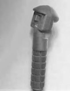
Hand Controls (Mechanical and Advanced Hand Controls)
Keep both feet on footrests while operating machine. Failure to do so can cause serious injury.
W–2152–0594
Put your feet on the footrests and KEEP THEM THERE for comfort and safety any time you operate the loader.
Two hand levers [A] control the hydraulic cylinders for the lift and tilt functions.
Lift Arm Operation
The left hand lever controls the lift arms. Move the left hand lever away (Item 1) [A] from the operator to raise the lift arms.
Move the left hand lever toward (Item 2) [A] the operator to lower the lift arms.
Lift Arm Float Position
Move the left hand lever all the way toward the operator (Item 2) [A] until it locks into thefloat position.
Later AHC Models With Float Button
– Press anbd hold the Float Button (Item 5) [A] before moving the lever. – Press again to disengage.
Use the float position of the lift arms to level loose material while driving backward.
Move the left hand lever upward to unlockfrom the float position.
Tilt Operation
The right hand lever controls the action of the bucket. Move the right hand lever away (Item 3) [A] from the operator to tilt the bucket forward.
Move the right hand lever toward (Item 4) [A] the operator to tilt the bucket backward.
Bucket Position Valve Operation (If Equipped)
The function of the bucket positioning valve is to keep the bucket in the same approximate position it is placed in before beginning the upward lift cycle.
Bucket positioning functions automatically during the upward lift cycle only.
The bucket positioning function (if equipped) can be turned OFF with the bucket level switch. (See Page 3).
Advanced Hand Controls (AHC) (If Equipped)
AHC operation is the same as mechanical hand controls above.
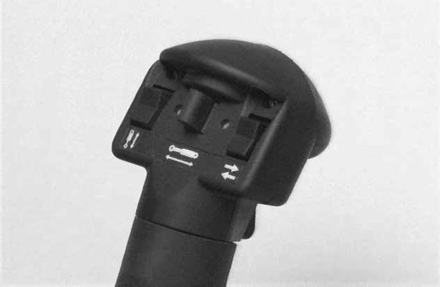
Two lights (Item 1) [B] on the left handle are always ON when the AHC is functioning correctly. If lights are blinking or do not come ON , see Advanced Hand Controls
Troubleshooting Chart Page 75.
HYDRAULIC CONTROLS (Cont’d)
Auxiliary Hydraulics (If Equipped) 7.
Avoid Burns
Hydraulic fluid, tubes, fittings and quick couplers can get hot when running machine and attachments. Be careful when connecting and disconnecting quick couplers.
W–2220–0396
NOTE:(Advanced Hand Controls Only) These loaders have auxiliary proportional control for front auxiliary hydraulics only. Proportional control allows for slow–to–fast movement of auxiliary functions. EXAMPLE: If you move the auxiliary switch half way, the auxiliary function will move at approximately one–half speed.
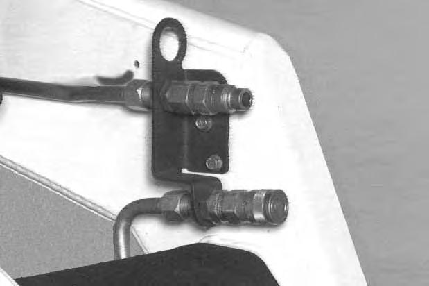
Quick Couplers
To Connect: Remove any dirt or debris from the surface of both the male and female coupler halves, and from the outside diameter of the male coupler. Visually check the couplers for corroding,cracking, damage, or excessive wear. If any of these conditions exist, the coupler(s) must be replaced [A].
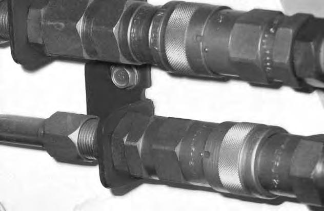
Install the male half coupler into the female half coupler. Full connection is made when the ball release sleeve slides forward on the female coupler and the sleeve is rotated so that the locking pins (Item 1) [B] and the groove (Item 2) [B] do NOT align (Locked Position). This will prevent accidental disconnection.
NOTE: If the locking pins and grooves (Item 3) [B] are aligned, accidental disconnection is possible.
To Disconnect: Rotate the ball release sleeve so that the grooves are aligned with thepins (Item 3) [B] in the female coupler.
Hold the male coupler. Retract the sleeve on the female coupler until the couplers disconnect.
HYDRAULIC CONTROLS (Cont’d)
Auxiliary Hydraulics (If Equipped) (Cont’d)
Auxiliary Hydraulics Switch
• Momentary Operation
Press the Auxiliary Hydraulics Switch (Item 1) [A] once.
The light (Item 2) [A] will be ON.
• Continuous Operation
Press the Auxiliary Hydraulics Switch (Item 1) [A] a second time.
Both lights (Items 2 & 3) [A] will be ON.
• Disengage
Press the Auxiliary Hydraulics Switch (Item 1) [A] a third time.
Both lights (Items 2 & 3) [A] will be OFF.
NOTE:When the operator is seated and raises the seat bar, the Auxiliary Hydraulic System (Front and Rear) will deactivate. Press the Auxiliary Hydraulics Switch to reselect operating mode.
FRONT Auxiliary Hydraulics Operation (RIGHT Steering Lever)
• Set the Auxiliary Hydraulics Switch for Momentary Operation. (See above.)
• Push the switch (Item 1) [B] or [C] to the right or left to change the fluid flow direction to the front quick couplers. (EXAMPLE: Open and close grapple teeth.)
FRONT Auxiliary Hydraulics Continuous Operation (RIGHT Steering Lever)
• Set the Auxiliary Hydraulics Switch for Continuous Operation (See above).
• Push the front switch (Item 2) [B] or [C] to give the front quick couplers a constant flow of fluid. (EXAMPLE: Operate a backhoe.)
• To release from continuous flow operation, press the front switch (Item 2) [B] or [C] a second time.
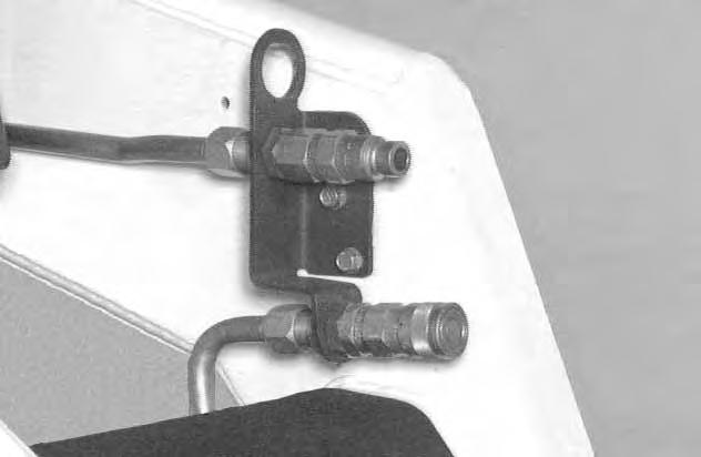
REAR Auxiliary Hydraulics Operation (LEFT Steering Lever)

• Set the Auxiliary Hydraulics Switch for Momentary or Continuous Operation. (See above.)

• Push the switch (Item 3) [B] or [C] to the right or left to change the fluid flow direction to the rear quick couplers [D]. (EXAMPLE: Raise and lower rear stabilizers.)
HYDRAULIC CONTROLS (Cont’d)
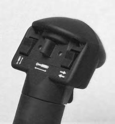
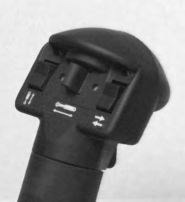
Attachment Functions Control
(Attachment Control Kit Required) (Item 1) [A]
When this kit is installed, you can use other switches on the right and left control handles (Deluxe Handles) for functions such as water spray, left/right turn signals (Europe only), raise/lower the left/right ends of the moldboard on a grader, etc.
The following are examples only, consult Attachment Operation & Maintenance Manual.
Switch (Item 1) [B] Left/Right Turn Signals . . .
Switch (Item 2) [B] Left Moldboard Up/Down . . .
Switch (Item 3) [B] Right Moldboard Up/Down Switch (Item 4) [B] Water Spray . . .
Diesel fuel or hydraulic fluid under pressure can penetrate skin or eyes, causing serious injury or death. Fluid leaks under pressure may not be visible. Use a piece or cardboard or wood to find leaks. Do not use your bare hand. Wear safety goggles. If fluid enters skin or eyes, get immediate medical attention from a physician familiar with this injury.
Relieving Hydraulic Pressure
8.
With the engine running, turn the key switch quickly to the left (counterclockwise) past the OFF position. Hold key for at least five seconds after the engine comes to a complete stop. This relieves pressure that can be trapped in the auxiliary circuit which would make it difficult to engage quick couplers from an attachment.
Daily Inspection
Maintenance work must be done at regular intervals. Failure to do so will result in excessivewear and early failures. The Service Schedule [A] is a guide for correct maintenance of the Bobcat loader. It is located inside the rear door of the loader and also in the Machine Sign Translation Section Page 77.
Daily Inspection and Maintenance:
• Engine Oil Level
• Hydraulic/Hydrostatic Fluid Level
• Engine Air Filter, Air System for Damage or Leaks
• Engine Coolant Level, System for Damage or Leaks
• Operator Cab, Seat Belt, Seat Bar, Pedal or Hand Control Interlocks & Mounting Hardware
• Grease Pivot Pins (Lift Arms, Bob–Tach, Cylinders, Bob–Tach Wedges
• Tires for Wear or Damage and Correct Air Pressure
• Fuel Filter, Remove Trapped Water
• Loose or Broken Parts
• Safety Treads and Safety Signs (Decals)
• Bobcat Interlock Control System (BICS ™)
• Lift Arm Support Device
NOTE:Fluids such as engine oil, hydraulic fluid, coolant, etc. must be disposed of in an environmentally safe manner. Some regulations require that certain spills and leaks on the ground must be cleaned in a specific manner. See local, state and federal regulations for correct disposal.
Instructions are necessary before operating or servicing machine. Read and understand Operation & Maintenance Manual, Handbook and signs (decals) on machine. Follow warnings and instructions in the manuals when making repairs, adjustments or servicing. Check for correct function after adjustments, repairs or service. Untrained operators and failure to follow instructions can cause injury or death.
W–2003–0199
Getting Ready For Operation
Read and understand the Operation & Maintenance Manual and the Operator’s Handbook (Item 1) [A] before operating the loader.
Operator must have instructions before running the machine. Untrained operators can cause injury or death.
W–2001–0596
The Operation & Maintenance Manual and other manuals can be kept in a box (Item 2)[A] provided at the right hand side of the operator seat.

Use the bucket or attachment steps, grab handles and safety treads (on top of the loader lift arms and frame) to get on and off the loader [B]
Safety treads are installed on the Bobcatloader to provide a slip resistant surface for getting on and off the loader. Keep safety treads clean and replace when damaged. See your Bobcat loader dealer for replacement treads.
Pull the seat lever (Item 1)[C] and adjust the seat position for comfortable operation of the loader controls.
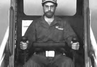
Fasten the seat belt snugly and adjust it so that the buckle is centered between your hips [D]
Avoid Injury Or Death
When operating the machine:
• Keep the seat belt fastened snugly.
• The seat bar must be lowered.
• Keep your feet on the pedal controls or footrests.
Failure to obey warnings can cause injury or death.
W–2261–0397
GETTING READY FOR OPERATION (Cont’d)
Lower the seat bar [A].
Be sure the parking brake is engaged.
Put all controls in the neutral positionbefore you start the engine.
After you start the engine, press the green PRESS TO OPERATE Button on the left instrument panel to operate lift, tilt and traction functions.
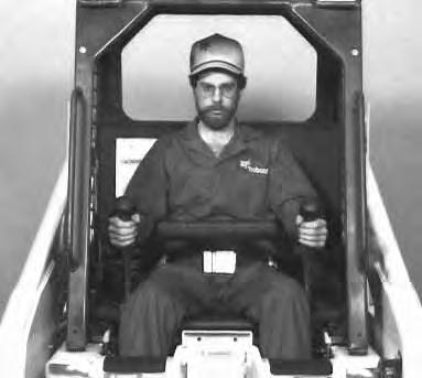
Foot Pedals: Keep your hands on the steering levers and feet on the foot pedals while seated in the loader [B]

Hand Controls: Keep your hands on the controls (Item 1) and feet on the footrests (Item 2) [C].
Starting The Engine
When an engine is running in an enclosed area, fresh air must be added to avoid concentration of exhaust fumes. If the engine is stationary, vent the exhaust outside. Exhaust fumes contain odorless, invisible gases which can kill without warning.
W–2050–1285
AVOID INJURY OR DEATH
• Engines can have hot parts and hot exhaust gas. Keep flammable material away.
• Do not use machines in atmosphere containing explosive gas.
W–2051–1086