10 minute read
MACHINE SIGNS (DECALS) (Cont’d)


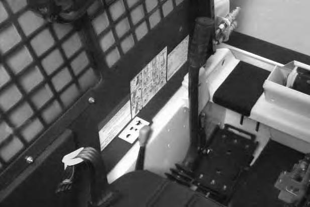
Instrument Panel
The following items are located on the instrument panel [A] and [B]:
1. TRACTION LOCK OVERRIDE BUTTON –(Functions Only When The Seat Bar Raised) Allows you to use the steering levers to move the loader forward or backward when using the backhoe attachment or for loader service. (See Page 5.)

2. SEAT SENSOR OVERRIDE BUTTON (If Equipped) (Functions Only When The Seat Bar Is Down) Allows operator, when seated with the seat bar lowered, to use lift, tilt, and traction functions if the seat sensor cannot be activated. (See Page 5.)
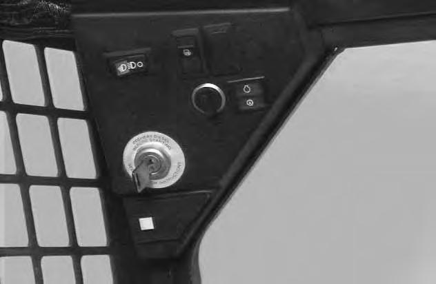
3. KEY SWITCH – For starting, stopping the engine.
4. BEACON SWITCH (Opt. or FA) – Controls the available flashing beacon light.
5. HAZARD SWITCH (FA) – Controls the available hazard indicators.
6. LIGHT SWITCH (Opt. or FA) – Controls the work and travel lights.
7. PREHEAT BUTTON – For preheating the glow plugs to aid cold temperature starting.
8. BUCKET LEVEL SWITCH (Opt. or FA) – Controls the ON/OFF function of the available bucket position valve.
9. ENGINE WARNING LIGHT – Light is ON when engine oil pressure is low or coolant temperature is high. Stop the engine if the light comes ON.
10. TRANSMISSION WARNING LIGHT – Low transmission charge pressure, hydraulic filter needs replacement or high fluid temperature. Stop the engine if the light comes ON.
11. HOURMETER – Records the total operating hours of the loader.
12. VOLTMETER – Shows the condition of the battery and the rate of charge.
13. ENGINE TEMPERATURE GAUGE – Shows the engine coolant temperature.
Opt . – Factory Installed Opt ion
FA – F ield Installed Accessory – See your Bobcat loader dealer about available Field Accessories.
BOBCAT INTERLOCK CONTROL SYSTEM (BICS™)
The Bobcat Interlock Control System (BICS ™) requires the operator to be seated in the operating position with the seat bar fully lowered before the lift, tilt and traction functions can be operated. The seat belt must be fastened any time you operate the loader.
The lift, tilt and traction drive functions are interlockedwith the seat bar. The lift and tilt functions are interlocked with the seat.
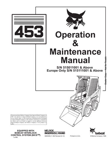
The BICS System Controller is located inside the cab behind and to the left of the operator’s seat [A].
There are five green lights on the BICS System Controller and all must be lighted to operate the loader [A].
The light functions are as follows [A]:
1. SEAT – ON when operator is in the seat.
2. SEAT BAR – ON when the seat bar is in down position.
3. VALVE – ON when lift and tilt hydraulic functions can be used.
4. TRACTION – ON when loader can be moved forward or backward.
5. POWER – ON when the Controller is operating correctly.
NOTE:If any of the lights are off or blinking, see the BICS Troubleshooting Chart Page 55 or see BICS Inspection and Maintenance Instructions Page 35.
Lift Arm By–Pass Control
The lift arm by–pass control knob (Item 1) [B] is used to lower the lift arms in the event that the lift arms can not be lowered during normal operating conditions.

With the operator in the seat, seat belt fastened and the seat bar fully lowered, pull and hold the by–pass control knob (Item 1) [B]. Push the top (toe) of theleft (lift) pedal. The lift arms will slowly lower.
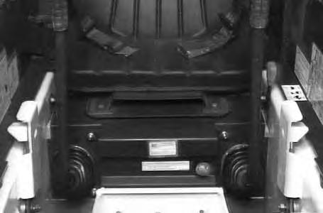
NOTE:The auxiliary hydraulic functions are not affected by the Bobcat Interlock Control System (BICS™).
AVOID INJURY OR DEATH
Before you leave the operator’s seat:
• Lower the lift arms, put the attachment flat on the ground.
• Stop the engine.
• Engage the parking brake.
• Raise seat bar, move pedals until both lock.
W–2045–1086
AVOID INJURY OR DEATH
The Bobcat Interlock Control System (BICS™) must deactivate the lift, tilt and traction drive functions. If it does not, contact your dealer for service. DO NOT modify the system.
W–2151–0394
BOBCAT INTERLOCK CONTROL SYSTEM (BICS™) (Cont’d)
Traction Lock Override
(Functions Only When The Seat Bar Is Raised) There is a traction lock override button (Item 1)[A] on the left hand instrument panel. It allows you to use the steering levers to move the loader forward & backward when using the backhoe attachment or for service.
Press the button once to unlock traction drive (green traction light on BICS Controller will be ON).
Press the button a second time to lock the traction drive (green traction light on BICS Controller will be OFF).
NOTE:The Traction Lock Override button will unlock the traction drive when the operator is NOT in the seat and the seat bar is raised.
The Traction Lock Override button will function if brake pedal is in the engaged or disengaged position.
Seat Sensor Override (If Equipped)
(Functions Only When The Seat Bar Is Down)
Seat Sensor Override button (Item 1)[A] allows operator, when seated with the seat bar lowered, to uselift, tilt, and traction functions if the seat sensor cannot be activated.
If seat indicator light on the BICS Controller does not go on, check for debris, dirt, or objects under or behind seat.
Engine Speed Control
The engine speed control (Item 1)[B] is at the left side of the operator’s seat. Engine speed is controlled bymoving the engine speed control forward to increase the engine RPM and backward to decrease the engine RPM.
Parking Brake
Engage the parking brake by pushing down on the top (toe) of the pedal [A]. The traction drive system will be locked.
To release the parking brake, push down on the bottom (heel) of the pedal [B].
NOTE:If the loader will not move when operator is in the operating position with brake pedal released or when traction lock override button is pushed, move the steering levers either forward or backward a small amount to unlock the traction drive.
Avoid Injury Or Death
When operating the machine:
• Keep the seat belt fastened snugly.
• The seat bar must be lowered.
• Keep your feet on the pedal controls.
W–2046–0595
The steering levers (Item 1) [A] are on the right and left side in front of the seat.
For safe control of the loader always move the levers slowly and smoothly. Only a small movement is necessary to move the loader.
The steering levers control forward and reverse travel of the loader [B]
Forward Travel – Push both levers forward.
Reverse Travel – Pull both levers backward.
Normal Turning – Move one leverfarther forward than the other.
Fast Turning – Push one lever forward and pull the other lever backward.
For slow travel speed, push the levers forward only a small amount.
To increase travel speed, push the levers farther forward.
For maximum pushing force, push the levers forward only a small amount with the engine at full RPM.
Forward
Reverse
Keep both feet on pedals while operating machine. Failure to do so can cause serious injury.
W–2002–1285
Stopping The Bobcat Loader
When the steering levers are moved to the neutral position, the hydrostatic transmission will act as aservice brake and stop the loader.
Left Turn
RIGHT TURN 453 Bobcat Loader Operation & Maintenance Manual –7–
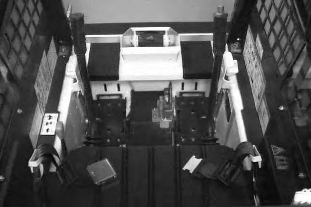
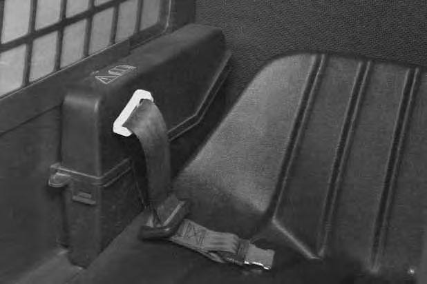
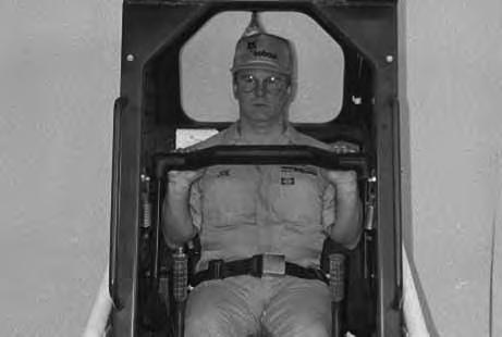
Seat Bar Restraint System
The seat bar restraint system has a pivoting seat bar (Item 1) [A] with arm rests and has spring loaded interlocks for the lift and tilt control pedals. The operator controls the use of the seat bar. The seat bar in the down position helps to keep the operator in the seat. The interlocks require the operator to lower the seat bar in order to operate the foot pedal controls. When the seat bar is up, the lift and tilt control pedals are locked when returned to the NEUTRAL POSITION
AVOID INJURY OR DEATH
When operating the machine:
• Keep the seat belt fastened snugly.
• The seat bar must be lowered.
• Keep your feet on the pedal controls.
W–2046–0595
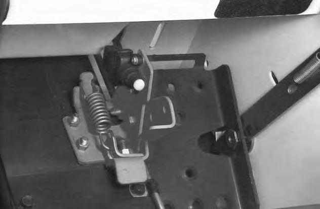
The spring loaded interlocks (Item 1) [B] control the locking and unlocking functions of the control pedals.
The interlocks (Item 1) [B] require the operator to lower the seat bar (Item 2) [B] which allows the operator to move the foot pedals to control the lift and tilt functions.
When the seat bar is lowered, it pushes the interlock (Item 1) [B] down on both sides, releasing the pedal linkages (Item 3) [B] from the interlocks.
The pedals will pivot in both directions when the interlock is down.
Before you leave the operator’s seat:
• Lower the lift arms, put the attachment flat on the ground.
• Stop the engine.
• Engage the parking brake.
• Raise the seat bar, move pedals until both lock.
• Move auxiliary control out of continuous operation position.
W–2164–1294
AVOID INJURY OR DEATH
The seat bar system must lock the lift and tilt control pedals in neutral when the seat bar is up. Service the system if pedals do not lock correctly.
W–2105–1285
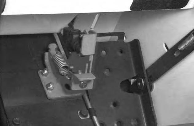
When the seat bar is raised, spring forces raise the interlocks [C]
The foot pedals will not pivot when the interlock is up.See Seat Bar Restraint System Inspection & Maintenance Page 35.

Hydraulic Controls
Foot Pedals
Keep both feet on pedals while operating machine. Failure to do so can cause serious injury.
Put your feet on the pedals and KEEP THEM THEREany time you operate the loader.
Two foot pedals (Item 1) [A] control the hydraulic cylinders for the lift and tilt functions.
Lift Arm Operation
The left pedal controls the lift arms. Push on the bottom (heel) (Item 2) [A] of the pedal to raise the lift arms.
Push on the top (toe) (Item 3) [A] of the pedal to lower the lift arms.
Lift Arm Float Position
Push the top (toe) (Item 3) [A] of the pedal all the way forward until it locks into float position.
Use the float position of the lift arms to level loose material while driving backward.
Push the bottom (heel) of the lift pedal to unlock from the float position.
Tilt Operation
The right pedal controls the action of the bucket.
Push the top (toe) (Item 4) [A] of the pedal to tilt the bucket forward.
Push the bottom of the pedal (heel) (Item 5) [A] to tilt the bucket backward.
Bucket Position Valve Operation (If Equipped)
The function of the bucket position valve is to keep the bucket in the same approximate position it is placed in, before beginning the upward lift cycle.
Bucket positioning functions automatically during the upward lift cycle only.
The bucket positioning function can be turned OFF with the bucket level switch. (See Page 3.)
HYDRAULIC CONTROLS (Cont’d)
Auxiliary Hydraulics (If Equipped)
Auxiliary hydraulics [A] are not standard, but can be a Factory Option or installed as a Field Accessory.

AVOID BURNS
Hydraulic fluid, tubes, fittings and quick couplers can get hot when running machine and attachments. Be careful when connecting and disconnecting quick couplers. W–2220–0396
Quick Couplers
Flush Face Couplers
To Connect: Remove any dirt or debris from the surface of both the male and female coupler halves, and from the outside diameter of the male coupler. Visually check the couplers for corroding, cracking, damage, or excessive wear, if any of these conditions exist, the coupler(s) must be replaced [A]

Install the male half coupler into the female half coupler. Full connection is established when the ball release sleeve slides forward on the female coupler and the sleeve is rotated so that the locking pins (Item 1)[B] and the groove (Item 2) [B] do NOT align (Locked Position).
NOTE:If the locking pins and groove (Item 3) [B] are aligned, accidental disconnection IS possible.
To Disconnect: Rotate the ball release sleeve so that the grooves are aligned with the pins (Item 3) [B] in the female coupler.
Hold the male coupler then retract the sleeve on the female coupler until the couplers disconnect.
HYDRAULIC CONTROLS (Cont’d)
Auxiliary Hydraulics (If Equipped) (Cont’d)
Avoid Burns
Hydraulic fluid, tubes, fittings and quick couplers can get hot when running machine and attachments. Be careful when connecting and disconnecting quick couplers.
W–2220–0396
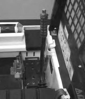
The auxiliary control has a lockbolt (Item 1)[A] that must be removed to use the auxiliary hydraulics.
Raise the operator cab (See Raising The Operator Cab Page 32).
Remove the nut and bolt from the righthand steering lever [A]
The right steering lever is also the control lever for the front auxiliary hydraulics [B]
Move the right steering lever to the left or to the right to activate the auxiliary hydraulics to operate an attachment. (Example: To open or close grapple teeth) [C]

Move the lever in the opposite direction to reverse the action of the attachment.
Auxiliary Hydraulic Continuous Operation
Move the steering lever all the way to the right (Item 1)[C] to put the control valve into the continuous operation position for a constant flow of hydraulic fluid under pressure to the quick couplers (Example: Backhoe operation).
Move the auxiliary control lever out of the continuous operation position before leaving the operator cab.
Relievng Hydraulic Pressure
Hydraulic pressure in the auxiliary hydraulic system can make it difficult to connect to the quick couplers.
To make connecting and disconnecting attachments easier, the hydraulic pressure can be relieved.
With the engine stopped and attachment flat on the ground, move the right steering lever to the leftand to the right several times [C]

Daily Inspection
The loader must be in good operating condition [A]
Check the following items before starting each day:
• Engine Oil
• Hydraulic/Hydrostatic Fluid
• Air Cleaner Condition Indicator
• Engine Cooling System
• Operator Cab, Seat Belt, Seat Bar & Pedal Interlocks
• Lift Arms & Cylinder Pivot Pins
• Tires & Tire Pressure
• Any Loose or Broken Parts
• Fuel Level
• Safety Tread & Safety Signs
• Bobcat Interlock Control System (BICS ™)
Follow the maintenance requirements on the Service Schedule Decal, located inside the rear door [B]
Fluids such as engine oil, hydraulic fluid, coolants, etc. must be disposed of in an environmentally safe manner. Some regulations require that certain spills and leaks on the ground must be cleaned in a specific manner. See local, state and federal regulations for correct disposal.
Instructions are necessary before operating or servicing machine. Read Operation & Maintenance Manual, Handbook and signs (decals) on machine. Follow warnings and instructions in the manuals when making repairs, adjustments or servicing. Check for correct function after adjustments, repairs or service. Failure to follow instructions can cause injury or death [A]. W–2003–0797
Getting Ready For Operation
Read the Operation & Maintenance Manual and the Operator’s Handbook before operating the loader (Item 1) [A].
Operator must have instructions before running the machine. Untrained operators can cause injury or death.
W–2001–0596
The Operation & Maintenance Manual and other manuals can be kept in a box provided at the right hand side of the operator seat (Item 1) [B]

Use the bucket or attachment steps, grab handles and safety treads (on top of the loader lift arm crossmember and main frame) to get on and off the loader [C]

Safety treads are installed on the Bobcatloader to provide a slip resistant surface for getting on and off the loader. Keep safety treads clean and replace when damaged. Replacement treads are available from your dealer.
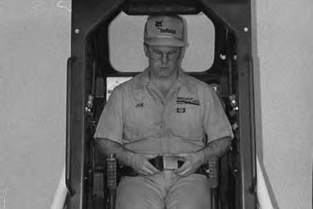
Fasten the seat belt snugly and adjust it so that the buckle is centered between your hips [D].
Avoid Injury Or Death
When operating the machine:
• Keep the seat belt fastened snugly.
• The seat bar must be lowered.
• Keep your feet on the pedal controls.
W–2046–0595
GETTING READY FOR OPERATION (Cont’d)
Lower the seat bar [A].
Be sure the parking brake is engaged. All controls must be in the NEUTRAL POSITION before you start the engine. (See Normal Starting Page 15.)