24 minute read
MAINTENANCE SAFETY


Instructions are necessary before operating or servicing machine. Read Operation & Maintenance Manual, Handbook and signs (decals) on machine. Follow warnings and instructions in the manuals when making repairs, adjustments or servicing. Check for correct function after adjustments, repairs or service. Failure to follow instructions can cause injury or death.
Safety Alert Symbol:This symbol with a warning statement, means: “Warning, be alert! Your safety is involved!” Carefully read the message that follows.
Correct
Correct
Correct
Never service the Bobcat® Skid Steer Loader without instructions.
Wrong
Use the correct procedure to lift or lower operator cab with lift arms down.
Cleaning and maintenance are required daily.
Wrong Wrong
Have good ventilation when welding or grinding painted parts. Wear dust mask when grinding painted parts. Toxic dust and gas can be produced.
Wrong
Stop, cool and clean engine of flammable materials before checking fluids.
Never service or adjust loader with the engine running unless instructed to do so in the manual. Avoid contact with leaking hydraulic fluid or diesel fuel under pressure. It can penetrate the skin or eyes.
Never fill fuel tank with engine running, while smoking or when near open flame.
Vent exhaust to outside when engine must be run for service. Avoid exhaust fume leaks which can kill without warning. Exhaust system must be tightly sealed.
Never work on loader with lift arms up unless lift arms are held by an approved lift arm support device. Replace if damaged. Never modify equipment or add attachments not approved by Melroe Company.
Wrong Wrong
Keep body, jewelry and clothing away from moving parts, electrical contacts, hot parts and exhaust.
Wear eye protection to guard from battery acid, compressed springs, fluids under pressure and flying debris when engines are running or tools are used. Use eye protection approved for type of welding. Keep rear door closed except for service. Close and latch door before operating the loader.
Lead–acid batteries produce flammable and explosive gases. Keep arcs, sparks, flames and lighted tobacco away from batteries. Batteries contain acid which burns eyes or skin on contact. Wear protective clothing. If acid contacts body, flush well with water. For eye contact flush well and get immediate medical attention.
Maintenance procedures which are given in the Operation & Maintenance Manual can be performed by the owner/operator without any specific technical training. Maintenance procedures which arenot in the Operation & Maintenance Manual must be performed ONLY BY QUALIFIED BOBCAT SERVICE PERSONNEL. Always use genuine Bobcat replacement parts.
Service Schedule
Maintenance work must be done at regular intervals. Failure to do so will result in excessive wear and early failures. The service schedule is a guide for correct maintenance of the Bobcat loader.
Instructions are necessary before operating or servicing machine. Read Operation & Maintenance Manual, Handbook and signs (decals) on machine. Follow warnings and instructions in the manuals when making repairs, adjustments or servicing. Check for correct function after adjustments, repairs or service. Failure to follow instructions can cause injury or death.
Engine Air Cleaner Empty the dust cup & replace the filter element as needed.
Engine Oil Check the oil level & add oil as needed.
Engine Cooling SystemClean debris from oil cooler and radiator. Check coolant level in recovery tank and add as needed.
Tires Check the air pressure & for damaged tires.
Indicators, Gauges Check for correct operation of all indicators, gauges & & Lights (Opt.) lights (Opt.).
Seat Belt and Seat Bar
Check the condition of seat belt. Check the seat bar & pedal interlocks for correct operation. Clean dirt and debris from moving parts.
Safety Signs (Decals) andCheck for damaged signs and safety treads. Replace any Safety Tread signs or safety treads that are damaged or worn.
Lift Arm and Bob–TachLubricate with multi–purpose lithium based grease.
Pivot Pin and Wedges
Engine Fuel Filter
Remove the water from the filter.
Hyd. Fluid, Hoses & Check fluid level & add as needed. Check for damage & Tubelines leaks. Repair & replace as needed.
Bobcat Interlock ControlCheck BICS™ System Controller functions. Clean dirt, System (BICS™) debris or objects from under or behind seat as required.
Battery Check cables, connections & electrolyte level. Add distilled water as needed
Control Pedals & SteeringCheck for correct operation repair or adjust as needed.
Bob–Tach Check locking levers & wedges for condition & operation.
Wheel Nuts Check for loose wheel nuts & tighten to 40–45 ft.–lbs. (54–61 Nm) torque.
Parking Brake Check operation.
Alternator Belt Check tension & adjust as needed.
Engine Oil & Filter Replace oil & filter. See engine Oil Chart.
Hydraulic Filter ElementReplace filter element.
Spark Arrestor MufflerClean the spark chamber.
Drive Belt Check drive belt for condition and tension.
Steering Lever PivotsLubricate grease fittings and oil hole in the steering shaft.
Engine Fuel Filter Replace filter element.
Hydraulic Reservoir BreatherReplace the breather cap.
Final Drive Trans (Chaincase) Replace the fluid.
Hydraulic/Hydrostatic Reservoir Replace the fluid.
Bobcat Interlock ControlCheck the lift arm by–pass control System (BICS™)
Check wheel nut torque every 8 hours for the first 24 hours. Also replace hydraulic/hydrostatic filter element when the transmission warning light stays on for five minutes after the fluid is at operating temperature. Or every 12 months.
Never work on a machine with the lift arms up unless the lift arms are secured by an approved lift arm support device. Failure to use an approved lift arm support device can allow the lift arms or attachment to fall and cause injury or death.

W–2059–0598
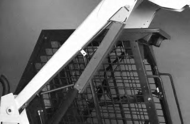
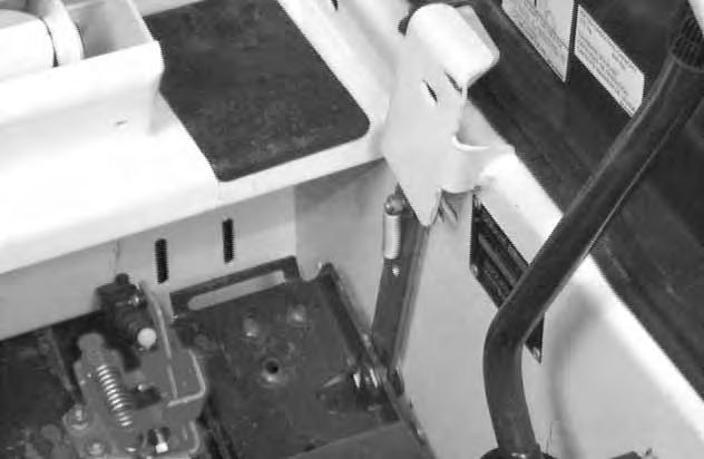
Installing The Lift Arm Support Device
Put jackstands under the rear corners of the loader (Inset) [A].
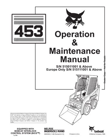
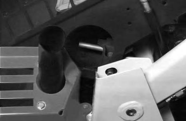
Disconnect the spring from the lift arm support device retaining pin (Item 1) [A], hold the support device and remove the retaining pin.
Lower the lift arm support device on top of the lift cylinder. Fasten the free end of the spring (Item 1)[B] to the lift arm support device so there will be no interference with the support device engagement.
With the operator in the seat, seat belt fastened, seat bar lowered and parking brrake engaged, start the engine.
Raise the lift arms until the lift arm support device drops onto the lift cylinder rod [C]
Lower the lift arms slowly until the support device is held between the lift arm and the lift cylinder. Stop the engine. Raise the seat bar and move pedals until both pedals lock.
Install the retaining pin (Item 1) [D] into the rear of the lift arm support device below the cylinder rod.
Service lift arm support device if damaged or if parts are missing. Using a damaged lift arm support or with missing parts can cause lift arms to drop causing injury or death.
W–2271–1197
LIFT ARM SUPPORT DEVICE (Cont’d)
Removing The Lift Arm Support Device
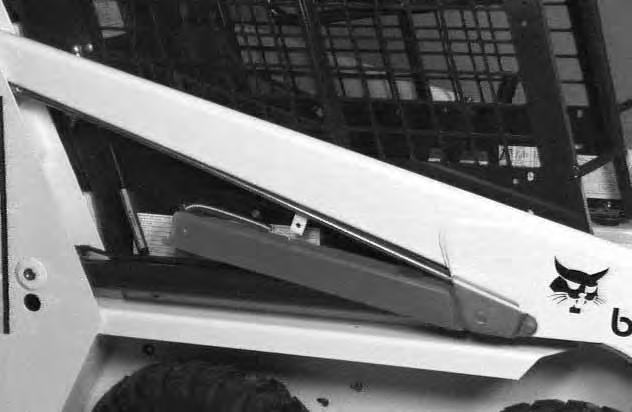
Remove the retaining pin (Item 1) [A] from the lift arm support device.
Connect the spring from the lift arm support device to the tubeline bracket (Item 1) [B] on the lift arms.
With the operator in the seat, seat belt fastened, seat bar lowered and parking brake engeaged, start the engine.
Raise the lift arms a small amount and the spring will lift the support device off the lift cylinder rod. Lower the lift arms. Stop the engine.
Raise the seat bar and move pedals until both pedals lock.
Disconnect the spring from the bracket.
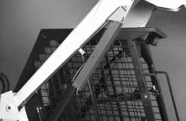
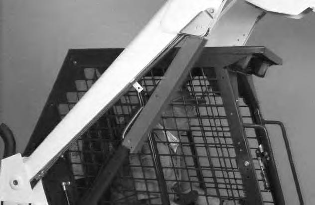
Raise the support device into storage position and insert pin through lift arm support device and bracket (Item 1) [C]
Connect spring to pin [C]
Operator Cab
The Bobcat loader has an operator cab (ROPS and FOPS) as standard equipment to protect the operator from rollover and falling objects. Check with your dealer if the operator cab has been damaged. The seat belt must be worn for roll over protection.
ROPS/FOPS Roll Over Protective Structure per SAE J1040 and ISO 3471, and Falling Object Protective Structure per SAE J1043 and ISO 3449, Level l
Level l – Protection from falling bricks, small concrete blocks and hand tools encountered in operations such as highway maintenance, landscaping, and other construction site services.
Check with your dealer if the operator cab has been changed.
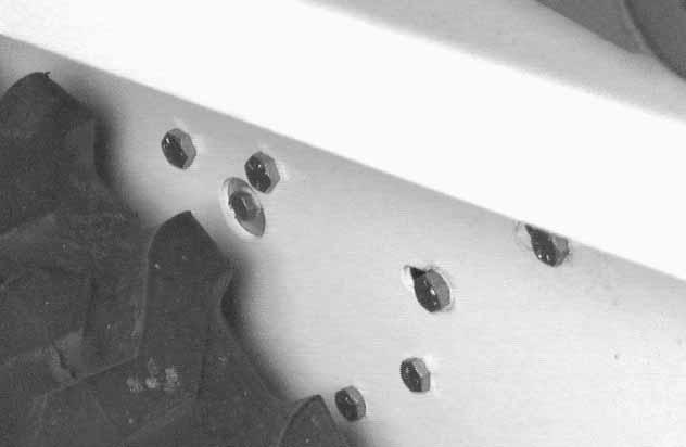
The operator cab fastening nuts (Item 1) [A] must be tightened to 40–50 ft.–lbs. (54–68 Nm) torque.
Before the cab or the lift arms are raised for service, jackstands must be put under the rear corners of the frame. Failure to use jackstands can allow the machine to tip backward causing injury or death.
W–2014–0895
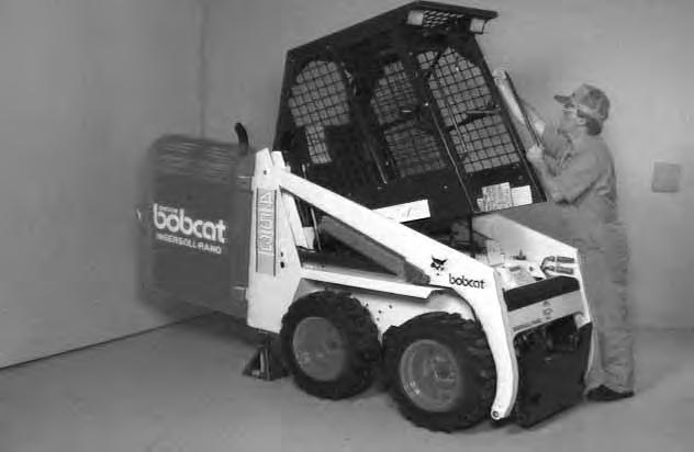
Raising The Operator Cab
Stop the loader on a level surface. Put the lift arms all the way down.
Open the rear door. (See REAR DOOR Page 37.)
If the lift arms must be up while raising the cab, install the lift arm support device. (See Installing The Lift Arm Support Device Page 30.)
Remove the two fasteners (Item 1) [A] at the front (both sides) of the operator cab.
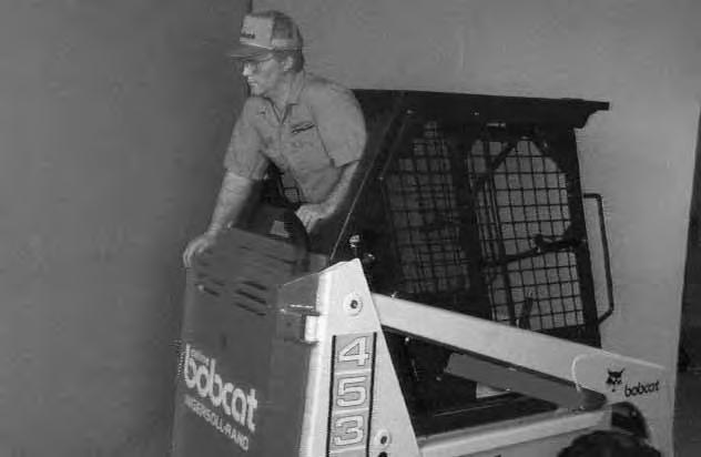
Stand on the ground. Lift slowly until operator cab is all the way up [B].
The operator cab will lock in the raised position.
Never modify operator cab by welding, grinding, drilling holes or adding attachments unless instructed to do so by Melroe Company. Changes to the cab can cause loss of operator protection from rollover and falling objects, and result in injury or death.
OPERATOR CAB (Cont’d)
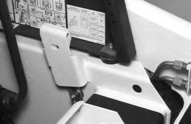
Lowering The Operator Cab
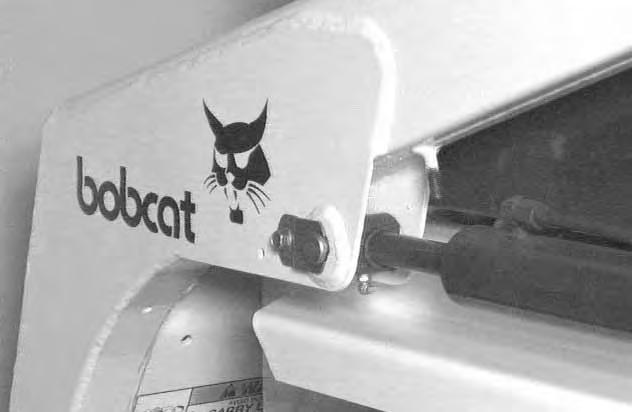
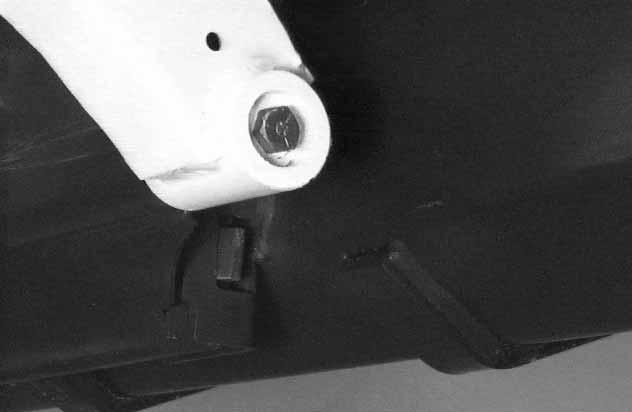
Hold the operator cab. Release the locking mechanismby pushing the lever (Item 1) [A] inward from the locked position (Item 2) [A] and turning the lever until it stays in the unlocked position [B]
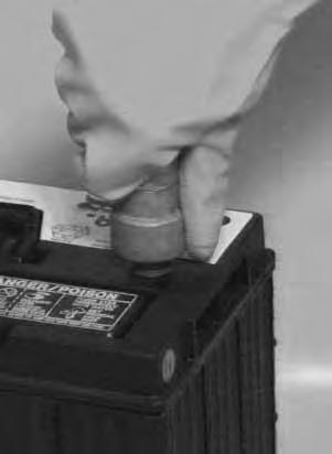
The cab must be held to prevent falling while hand is in access hole.
REMOVE YOUR HAND FROM THE HOLE BEFORE LOWERING THE OPERATOR CAB
Stand on the ground and pull down on the operator cab. Avoid slippery surfaces when lowering the cab.
NOTE:Guide the operator cab over the fastening bolts to prevent thread damage.
Install the cab washers and nuts. Tighten the nuts (Item 1) [C] (both sides) to 40–50 ft.–lbs. (54–68 Nm) torque.
OPERATOR CAB (Cont’d)
Emergency Exit
The front opening on the operator cab and rear window provide exits.

Pull on the tag at the top of the rear window to remove the rubber cord [A]
Push the rear window out of the rear of the operator cab.
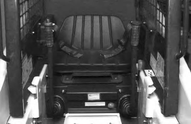
Seat Bar Restraint System
The seat bar restraint system hasa pivoting seat bar with arm rests and has spring loaded interlocks forthe lift and tilt control pedals. The operator controls the use of the seat bar. The seat bar in the down position helps to keep the operator in the seat. The interlocks require the operator to lower the seat bar in order to operate thefoot pedal controls. When the seat bar is up, the lift and tilt pedals are locked when returned to the neutral position.
Avoid Injury Or Death
The seat bar system must lock the lift and tilt control pedals in neutral when the seat bar is up. Service the system if pedals do not lock correctly.
Seat Bar Inspection
Sit in the seat and fasten the seat belt. Engage the parking brake. Pull the seat bar all the way down. Start the engine.
Operate each foot pedal to check both the lift and tilt functions.
Raise the lift arms until the bucket is about 2 feet (600 mm) off the ground. Raise the seat bar, try to move each pedal. The pedals must be firmly locked in neutral position. There must be no motion of the tilt(bucket) or the lift arms when the pedals are pushed.
Pull the seat bar down, lower the lift arms. Operate the lift pedal. While the lift arms are going up, raise the seat bar and the lift arms should stop.
Lower the seat bar, lower the lift arms and place the bucket flat on the ground. Stop the engine. Raise the seat bar and operate the foot pedals to be sure that the pedals are firmly locked in the neutral position. Unbuckle the seat belt.
Seat Bar Maintenance
See the SERVICE SCHEDULE Page 29 and on the loader for correct service interval.
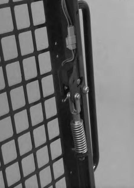
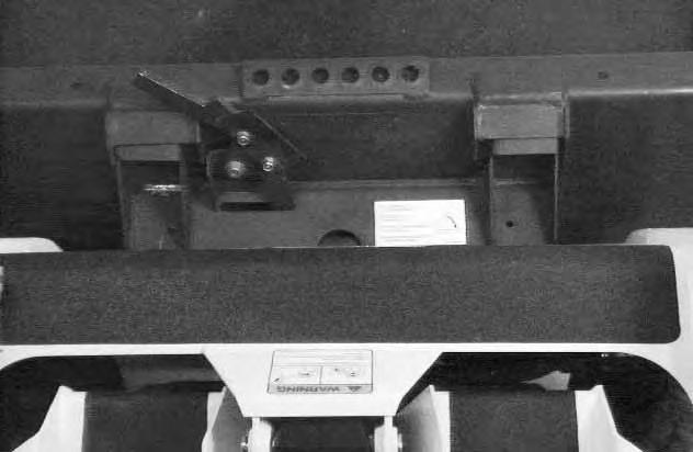
Clean any debris or dirt from the moving parts [A] & [B].
Inspect the linkage bolts and nuts for tightness. The correct torque is 25–28 ft.–lbs. (34–38 Nm).
If the seat bar system does not function correctly, check for free movement of each linkage part. Check for excessive wear. Adjust pedal control linkage. Replace parts that are worn or damaged. Use only genuine Melroe replacement parts.
Foot Pedal Clean Out
Clean any debris from around the foot pedals. Debris will fall out through the holes under the pedals (Item 1) [C].
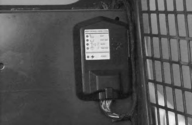
BOBCAT INTERLOCK CONTROL SYSTEM (BICS™)
Inspecting The BICS™ System Controller (Engine STOPPED – Key ON)
Sit in the operator’s seat. Turn key ON, lower the seat bar and disengage the parking brake. All five (5) BICS ™ System Controller lights should be ON (Items 1, 2, 3, 4 & 5) [A].
Engage the parking brake, raise the seat bar fully. Seat bar light (Item 2) [A], valve light (Item 3) [A] and traction light (Item 4) [A] should be OFF.
Raise up slightly off the seat. Seat light (Item 1)[A] should be OFF.
NOTE:Record what lights are blinking (if any) and number of blinks. Refer to Page 60.
Exit the loader and press traction lock override button. Traction light (Item 4) [A] should be ON. Press override button again and traction light (Item 4)[A] should be OFF.
Inspecting The Seat And Seat Bar Sensors (Engine RUNNING)
Sit in the operator’s seat, lower the seat bar and engage the parking brake. Fasten the seat belt.
Start the engine and operate at low idle. While raising the lift arms, raise the seat bar fully. The lift arms should stop. Repeat using the tilt function.
NOTE:The auxiliary hydraulic functions are not affected by the Bobcat Interlock Control System (BICS™).
Inspecting The Traction Lock (Engine RUNNING)
Sit in the operator’s seat.
Fasten the seat belt, disengage the parking brake, and raise the seat bar fully. Move the steering levers slowly forward and backward. The traction lock should be engaged. Lower the seat bar.
Engage the parking brake pedal and move the steering levers slowly forward and backward. The traction lock should be engaged.
Inspecting
The Lift Arm By–Pass Control
Raise the lift arms six feet (2 m) off the ground. Stop the engine, pull and hold the by–pass controlknob. Push the toe of the left foot pedal and the lift arms should lower slowly.
Maintenance
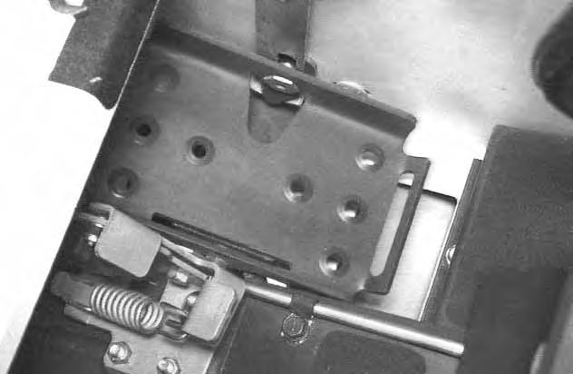
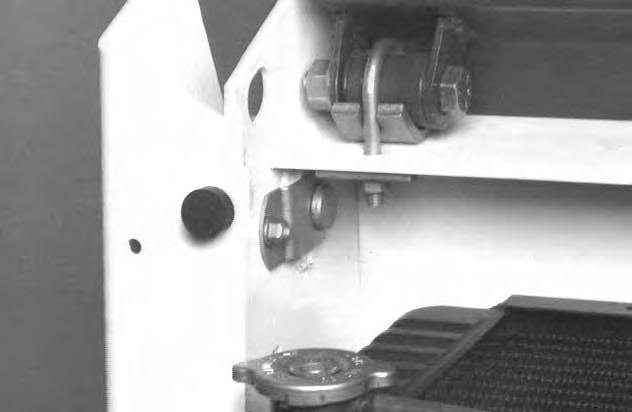
Clean any debris, dirt or objects from under or behind the operators seat [B] & [C]. The right side of the seat must move up and down.
Inspect both seat rail covers [C] for wear or damage. Replace if necessary.
Clearance is necessary between the seat mount (Item 1) [C] and the seat pan, to allow the seat to move up and down freely. With adequate clearance, the seat sensor will be allowed to function properly.
Inspect seat bar pivot area for tightness of linkage bolts.
Replace parts that are damaged. Use only genuine Melroe replacement parts.
AVOID INJURY OR DEATH
The Bobcat Interlock Control System (BICS™) must deactivate the lift, tilt and traction drive functions. If it does not, contact your dealer for service. DO NOT modify the system.
W–2151–0394
Avoid Injury
Never service or adjust the machine when the engine is running unless instructed to do so in this manual.
W–2012–0290
Open the rear door to service the engine. Pull the latch pin (rotate clockwise) on the left side of the rear door [A]. Open the rear door.
Keep the rear door closed when operating the machine. Failure to do so could seriously injure a bystander.
W–2020–1285

Air Cleaner Service
See the SERVICE SCHEDULE Page 29 for the interval to service the air cleaner system.
Check the air intake hose for damage.
Check the air cleaner housing for damage.
Check to make sure all connections are tight.
Loosen the wing nut (Item 1) [A]
Remove the cover (Item 1) [B].
Remove the dust cup (Item 2) [B].
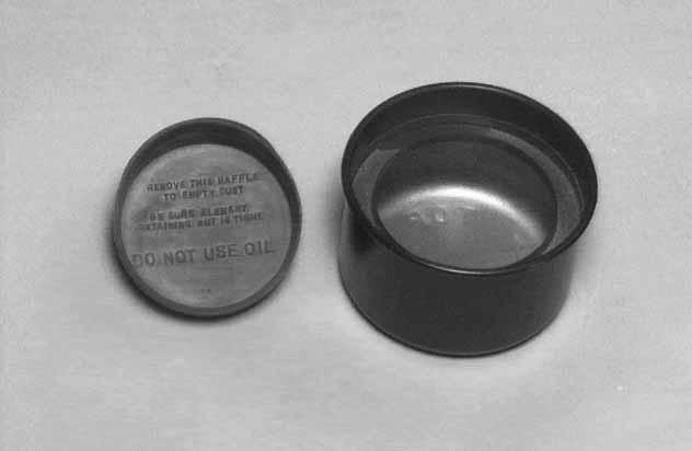
Empty the debris from the dust cover.
Remove the wing nut (Item 1) [C] from the air filter.
Remove the air filter (Item 1) [D]
NOTE:Make sure all sealing surfaces are free of dirt and debris.
Install a new air filter using the wing nut.
Install the dust cup and cover.
Fuel System
Fuel Specifications
Use only clean, high quality diesel fuel, Grade No. 2 or Grade No. 1.
The following is one suggested blending guideline which should prevent fuel gelling problems:
Temp. F°/C° No. 2No. 1
+15o(–9o) 100% 0%
Down to –20o/–29o 50% 50% Below –20o/–29o 0% 100%
We recommend an operator contact their fuel supplier for local recommendations.
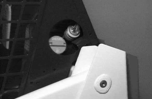
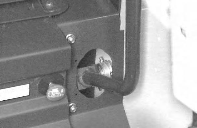
The fuel gauge (Item 1) [A] and the fuel shut off valve (Item 2) [A] are located on the right side of the loader.
Stop and cool the engine before adding fuel. NO SMOKING! Failure to obey warnings can cause an explosion or fire.
Filling The Fuel Tank
Remove the fuel fill cap[B] from the left side of the loader. Use a clean, approved safety container to add fuel of the correct specifications. Add fuel only in an area that has free movement of air and no open flames or sparks. NO SMOKING [C]
Install and tighten the fuel fill cap [B].
Always clean up spilled fuel or oil. Keep heat, flames, sparks or lighted tobacco away from fuel and oil. Failure to use care around combustibles can cause explosion or fire which can result in injury or death.W–2103–1285
Always clean up spilled fuel or oil. Keep heat, flames, sparks or lighted tobacco away from fuel and oil. Failure to use care around combustibles can cause explosion or fire which can result in injury or death.W–2103–1285
Fuel Filter
Drain Water:
See the SERVICE SCHEDULE Page 29 for the service interval when to remove the water from the fuel filter.
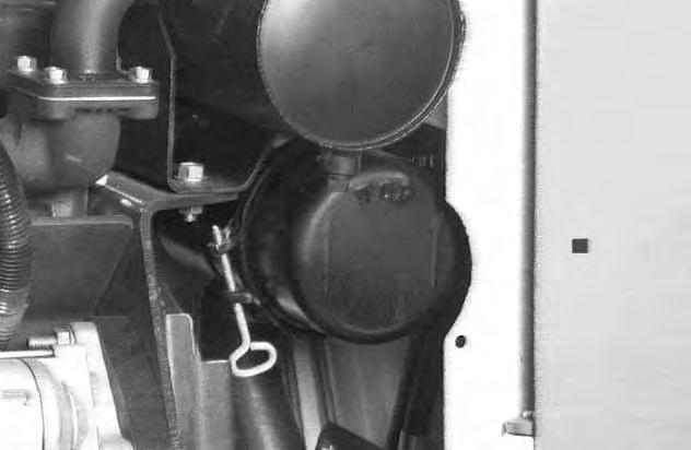
Turn the fuel shut–off valve (Item 1) [A] clockwise to shut off the fuel supply.
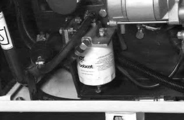
Loosen the drain (Item 1) [B] at the bottom of the filter element to drain the water from the filter. Close the drain.
Open the shut–off valve (Item 1) [A] to turn on the fuel supply.
Replace Fuel Filter:
See the SERVICE SCHEDULE Page 29 for the service interval when to replace the fuel filter.
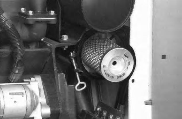
Clean the area around the fuel filter.
Close the shut–off valve (Item 1) [A].
Remove the fuel filter [B].
NOTE:Be sure the filter gasket is removed with the old fuel filter.
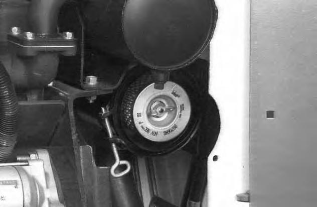
Install the new filter element hand tight. Open the shut–off valve (Item 1) [A].
FUEL SYSTEM (Cont’d)
Removing Air From The Fuel System
After replacing the fuel filter element or when the fueltank has run out of fuel, the air must be removed from the fuel system before starting the engine.
Be sure the engine is cool.
Open the rear door.
Open the vent plug (Item 1) [A]
Operate the hand pump priming bulb (Item 2)[A] until fuel flows from the vent plug with no air bubbles.
Close the vent plug (Item 1) [A]
With the operator in the seat, seat belt fastened, seat bar lowered and parking brake engaged, start the engine.
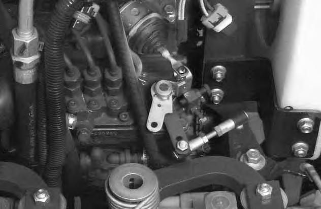
NOTE:If the engine fails to start, remove air from the fuel injection pump as follows.
Put jackstands under the rear of the frame and raise the operator cab. (See Raising The Operator Cab Page 32.)
Open the valve (Item 1) [B] on the injector pump and squeeze the hand pump (Item 2) [A] several times until fuel comes from the valve.
Close the valve (Item 1) [B]
Lower the operator cab. (SeeLowering The Operator Cab Page 33.)
Always clean up spilled fuel or oil. Keep heat, flames, sparks or lighted tobacco away from fuel and oil. Failure to use care around combustibles can cause explosion or fire which can result in injury or death.W–2103–1285
Engine Lubrication System
Check the oil level every day.
Stop the engine and remove the dipstick (Item 1) [A]
Keep the oil level between the marks on thedipstick.Use a good quality motor oil that meets API Service Classification of CD or better. (See Oil Chart below.)
Replacing Oil And Filter
See the SERVICE SCHEDULE Page 29 for the service interval for replacing the engine oil and filter.
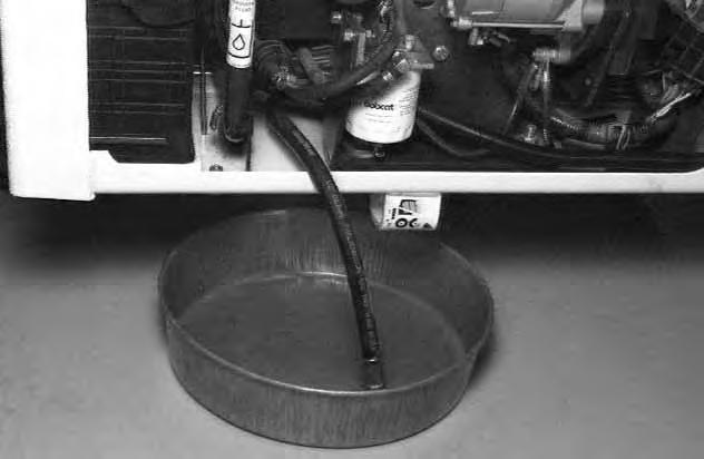
Run the engine until it is at operating temperature. Stop the engine.
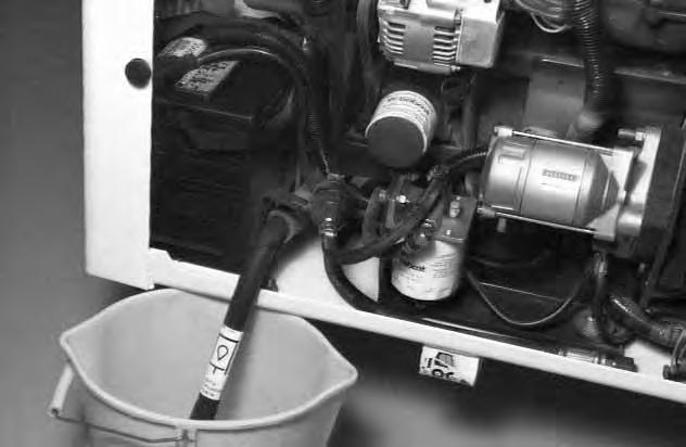
Open the rear door and remove the cap from the hose. Drain the oil into a container [B]. Install the cap on the drain hose.
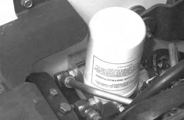
Remove the filter (Item 2) [A]
Clean the filter housing surface. Put clean oil on the gasket of the new filter. Install the filter and hand tighten. Remove the oil fill cap (Item 1) [C]
Oil Chart
RECOMMENDED SAE VISCOSITY NUMBER (LUBRICATION OILS FOR DIESEL ENGINE CRANKCASE)
C° –34–29–23–18–13–7–1+4+10+15+21+27+32+38+43+49
SAE 10W–30
* SAE 5W–30
SAE 15W–40
SAE 40W or 20W–50
SAE 30W
–40
SAE 20W–20
SAE 10W
SYNTHETIC OIL Use recommendation from Synthetic Oil Mfgr.
F° –30–20–100+10+20+30+40+50+60+70+80+90+100+110+120
TEMPERATURE RANGE ANTICIPATED BEFORE NEXT OIL CHANGE (DIESEL ENGINES MUST USE API CLASSIFICATION CD, CF4, CG4 ) * Can be used ONLY when available with appropriate diesel rating.
Fill to capacity. (See SPECIFICATIONS Page 69.)
Start the engine and let it run for about 5 minutes. Check for leaks at the filter. Check the oil level. Add oil until the level is at the FULL mark on the dipstick. Install the oil fill cap (Item 1) [C]
NOTE:DO NOT overfill the crankcase.
Cooling System
Check the cooling system every day to prevent overheating, loss of performance or engine damage.
Checking The Coolant Level
Open the rear door.
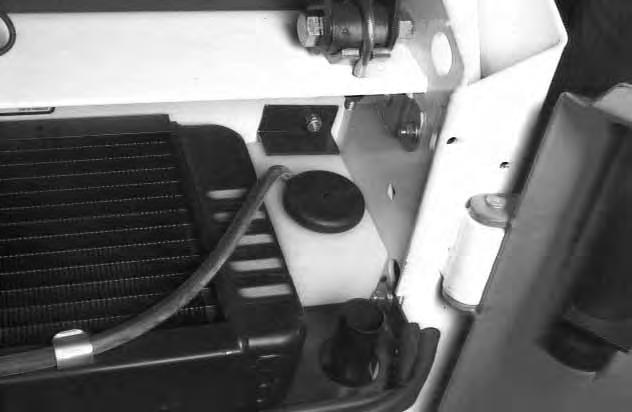
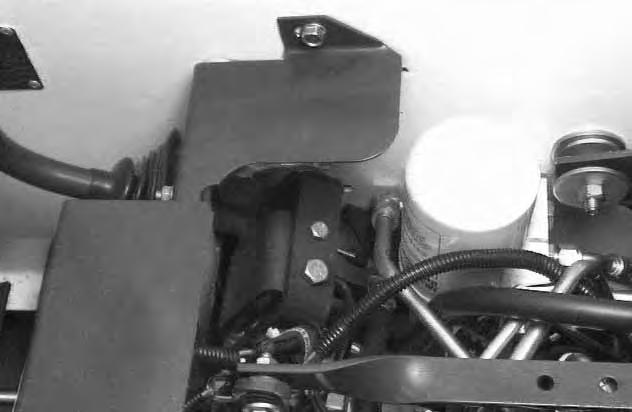
The coolant recovery tank (Item 1)[A] is located between the radiator and the right upright.
The coolant level in the recovery tank must be between the maximum and minimum mark when engine is cool [A].
NOTE:The loader is factory filled with propylene glycol coolant. DO NOT mix propylene glycol with ethylene glycol.
Propylene Glycol
Add premixed coolant; 47% water and 53% propylene glycol to the recovery tank if the coolant level is low.
One gallon and one pint of propylene glycol mixed with one gallon of water is the correct mixture of coolant to provide a –34°F (–37°C) freeze protection.
Use a refractometer to check the condition of propylene glycol in your cooling system.
Use safety goggles when using air or water under pressure. Do not use cold water to clean a hot engine. Failure to obey warnings can cause serious injury.
Cleaning The Cooling System
Open the rear door.
Use air pressure or water pressure to remove the debris in the area of the radiator and oil cooler.
Removing Coolant From The Cooling System
Open the rear door.
Put the drain hose (Item 1) [B] into a clean container.
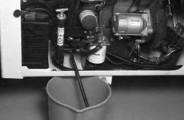
Raise the operator cab. (See Raising The Operator Cab Page 32.)
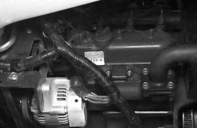
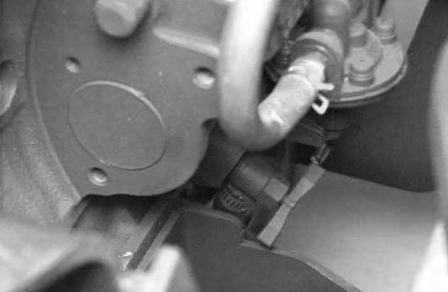
Open the drain valve (Item 1) [C]. (Located on front of engine, near the fuel lift pump.)
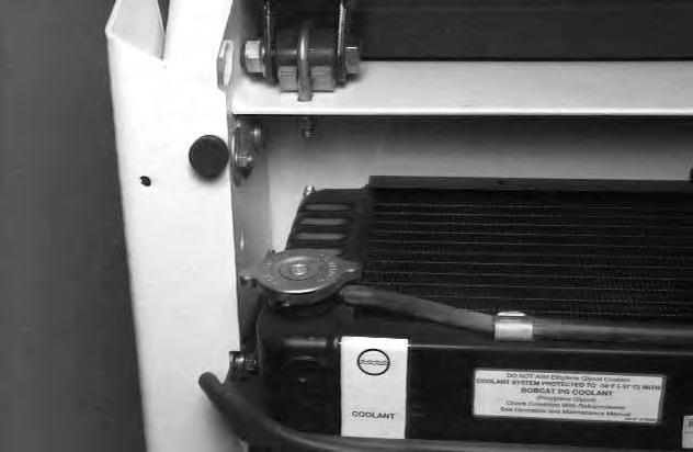
Remove the radiator cap [D]
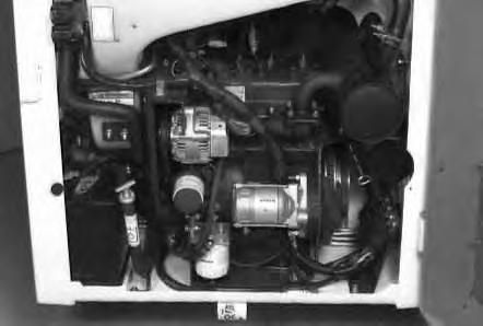
Alternator Belt Adjustment
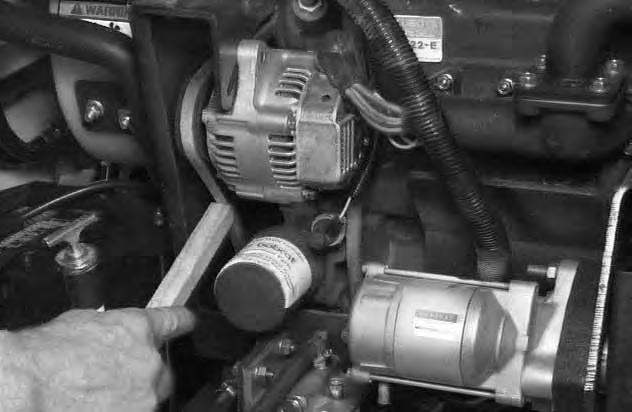
Stop the engine.
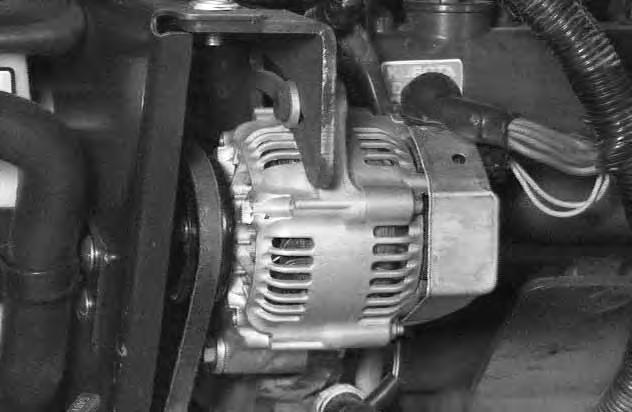
Loosen the mounting bolts (Item 1) [A] and move the alternator.
Set the belt tension to 1/4 inch (6 mm) movement between pulleys with 15 pounds (67 N) of force [B] Tighten the mounting bolts.
Electrical System
Description
The loader has a 12 volt, negative ground alternator charging system.
The electrical system is protected by 6 fuses.
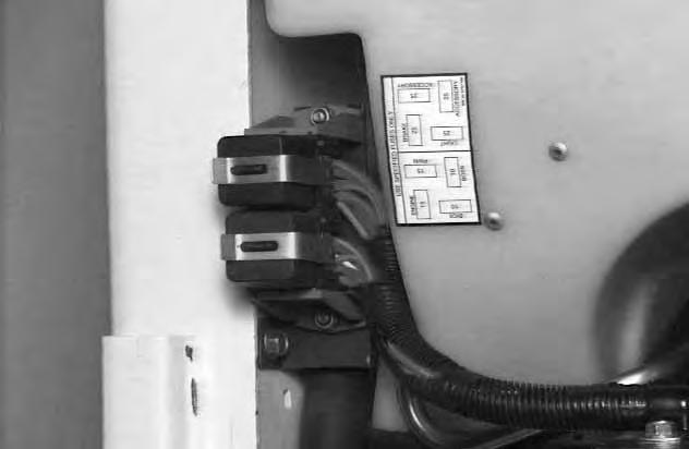
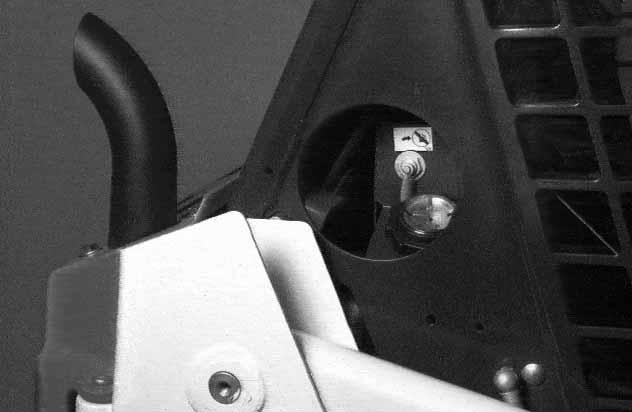
Fuse Location
The fuses are located under the fuse covers (Item 1) [C] located in the engine compartment.
Electrical System Service
The battery cables must be clean and tight. Remove any acid or corrosion from the battery and cables with a baking soda and water solution. Cover the terminals of the battery with Melroe Battery Saver (P/N 886398) to prevent corrosion.
Install the terminal covers.
ELECTRICAL SYSTEM (Cont’d)
Battery Removal And Installation
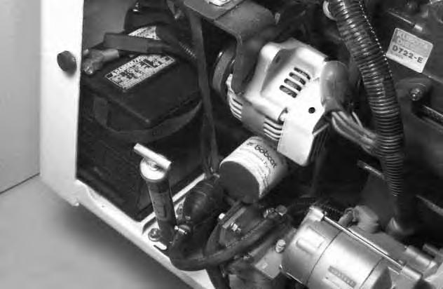
Open the rear door. Disconnect the negative (–) battery cable first (Item 1) [A]
Remove the battery holddown clamp (Item 2) [A]
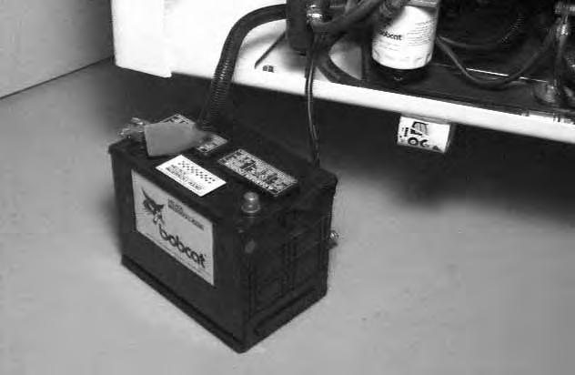
Remove the battery from the loader [B]
Disconnect the positive (+) cable (Item 1) [B]
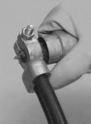
Always clean the terminals and cable ends when installing a new battery [C]
When installing the battery in the loader, do not touch any metal parts with the battery terminals.
Connect and tighten the battery cables. Connect the negative (–) cable last to prevent sparks.
Batteries contain acid which burns eyes and skin on contact. Wear goggles, protective clothing and rubber gloves to keep acid off body.
In case of acid contact, wash immediately with water. In case of eye contact get prompt medical attention and wash eye with clean, cool water for at least 15 minutes.
If electrolyte is taken internally drink large quantities of water or milk! DO NOT induce vomiting. Get prompt medical attention.
W–2065–1296
Keep arcs, sparks, flames and lighted tobacco away from batteries. When jumping from booster battery make final connection (negative) at engine frame.
Do not jump start or charge a frozen or damaged battery. Warm battery to 60°F. (16°C.) before connecting to a charger. Unplug charger before connecting or disconnecting cables to battery. Never lean over battery while boosting, testing or charging.
Battery gas can explode and cause serious injury.
W–2066–1296
ELECTRICAL SYSTEM (Cont’d)
• Engine is operated with battery cables disconnected.
• Battery cables are connected when using a fast charger or when welding on the loader (Remove both cables from the battery)
• Extra battery cables (booster cables) are connected wrong.
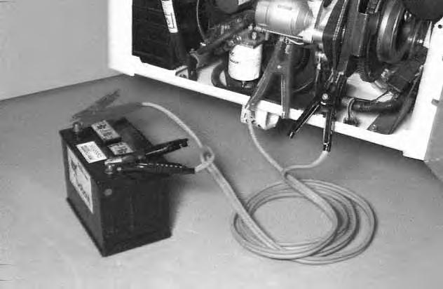
If it is necessary to use an extra battery to start theengine, BE CAREFUL! There must be one person in the operator’s seat and one person to connect and disconnect the battery cables.
The ignition must be in the OFF position.
The battery must be 12 volt.
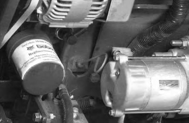
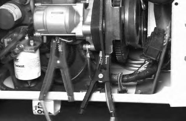
Connect one end of the first cable (Item 1) [A] to the positive terminal (+) of the booster battery. Connect the other end of the same cable (Item 2)[A] to the positive (+) terminal on the starter.
Connect one end of the second cable (Item 3) [A] to the negative terminal (–) of the booster battery. Connect the other end of same cable (Item 4) [A] to the engine mounting frame.
Keep the cables away from moving parts. Start the engine.
After the engine has started, remove the ground cable connected to the engine first.
Remove the cable connected to the loader battery.
HYDRAULIC/HYDROSTATIC SYSTEM
The hydraulic and hydrostatic systems use the same hydraulic fluid reservoir.
The system has an engine driven gear pump that supplies fluid to the control valve, lift and tilt cylinders.
Fluid also goes from the control valve to the hydrostatic transmission pumps to provide charge pressure and cooling.
A hydraulic filter element is installed under the cab near the right side. This filter is used to clean the fluid for the hydrostatic transmission pumps.
The location of the oil cooler is above the engine. The oil cooler is used for cooling the hydraulic fluid before it returns to the hydrostatic transmission pumps.
Checking And Adding Fluid
Put the Bobcat loader on a level surface. Lower the lift arms and tilt the bucket fully backward.
Open the rear door. Remove the dipstick (Item 1) [A]
The fluid level is correct if the fluid level is between the marks on the dipstick.
NOTE:The dipstick may indicate an incorrect level of fluid when first removed because of expansion or contraction of oil in the fill tube. Always (1) remove the dipstick, (2) wipe the dipstick, (3) insert the dipstick again and (4) re–check the fluid level.
Add fluid until it is at the correct level.
Diesel fuel or hydraulic fluid under pressure can penetrate skin or eyes, causing serious injury or death. Fluid leaks under pressure may not be visible. Use a piece of cardboard or wood to find leaks. Do not use your bare hand. Wear safety goggles. If fluid enters skin or eyes, get immediate medical attention from a physician familiar with this injury.
W–2072–0496
HYDRAULIC/HYDROSTATIC SYSTEM (Cont’d)
Replacing The Hydraulic/Hydrostatic Filter Element
See the SERVICE SCHEDULE Page 29 for the correct service interval.
Stop the engine. Open the rear door. Raise the operator cab. (See Raising The Operator Cab Page 32.) Clean the area around the filter housing. Remove the plug (Item 1) [A] from the filter housing (located on the outside of the loader at the right side).
After the fluid is drained from the filter, install the plug (Item 1) [A] and tighten.
Remove the filter element (Item 1) [B]
Clean the surface of the filter housing where the filter element seal contacts the filter housing.
Put grease on the seal of the filter element, install the element and hand tighten only.
Lower the operator cab.
Start the engine and operate the loader through the hydraulic and hydrostatic functions. Stop the engine. Check the fluid level and add fluid to the reservoir as needed.
Removing The Hydraulic/Hydrostatic Fluid
See the SERVICE SCHEDULE Page 29 for the service interval to replace the fluid. The fluid must also be replaced if it becomes contaminated and after any major repairs.
Stop the engine. Open the rear door.
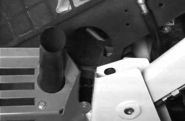
Remove the fill cap/dipstick.
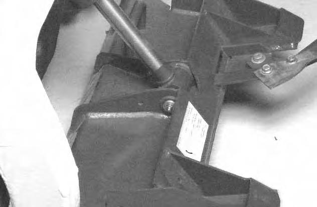
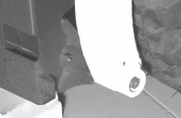
Loosen the nut (Item 1) [C] which fastens the fill tube to the loader frame.
Loosen the clamp at the fill tube, turn the fill tube down to drain the fluid from the reservoir [C]
After the fluid is removed, put the fill tube in the correct position, tighten the hose clamp and tighten the bolt.
Replace the hydraulic filter element.
Add hydraulic/hydrostatic fluid to the reservoir. (See SPECIFICATIONS Page 69 for the correct fluid.)
Do Not over–fill the reservoir.
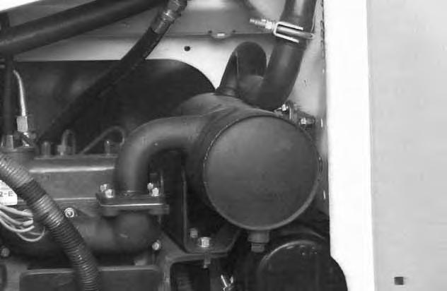
Spark Arrestor Muffler
See the SERVICE SCHEDULE Page 29 for correct service interval. Do not operate the loaderwith a defective exhaust system.
Stop engine and allow the muffler to cool before cleaning the spark chamber. Wear safety goggles. Failure to obey can cause serious injury.
W–2011–1285
When an engine is running in an enclosed area, fresh air must be added to avoid concentration of exhaust fumes. If the engine is stationary, vent the exhaust outside. Exhaust fumes contain odorless, invisible gases which can kill without warning.
W–2050–1285
Stop the engine. Open the rear door.
Remove the plug (Item 1) [A] from the bottom of the muffler.
This loader is factory equipped with a U.S.D.A. Forestry Service approved spark arrestor muffler. It is necessary to do maintenance on this spark arrestor muffler to keep it in working condition. The spark arrestor muffler must be serviced by dumping the spark chamber every 100 hours of operation.
If this machine is operated on flammable forest, brush or grass covered land, it must be equipped with a spark arrestor attached to the exhaust system and maintained in working order. Failure to do so will be in violation of California State Law, Section 4442 PRC.
Never use machine in atmosphere with explosive dust or gases or where exhaust can contact flammable material. Failure to obey warnings can cause injury or death.
W–2068–1285
Start the engine.
Have a second person (wearing safety goggles) hold a block of wood over the outlet of the muffler (with the engine running) for about 10 seconds.
This will force contaminants out through the cleanout hole.
Stop the engine and install the plug. Close the rear door.
Make reference to local laws and regulations for spark arrestor requirements.
I–2022–0595
When the engine is running during service, the steering levers must be in neutral and the parking brake engaged. Failure to do so can cause injury or death.
W–2006–0284
Tire Maintenance
Wheel Nuts
See the SERVICE SCHEDULE Page 29 for the service interval to check the wheel nuts. The correct torque is 40–45 ft.–lbs. (54–61 Nm).
Tire Rotation
Check the tires regularly for wear, damage and pressure (See SPECIFICATIONS Page 69 for the correct tire pressure).
Rear tires usually wear faster than front tires. To keep tire wear even, move the front tires to the rear and rear tires to the front [A].
It is important to keep the same size tires on each side of the loader to avoid excessive wear. If different sizes are used, each tire will be turning at a different rate and cause excessive wear. The tread bars of all the tires must face the same direction.
Recommended tire pressure must be maintained to avoid excessive tire wear and loss of stability and handling capability. Check for the correct pressure before operating the loader.
Do not inflate tires above specified pressure. Failure to use correct tire mounting procedure can cause an explosion which can result in injury or death.
Tire Inflation
Tires are to be repaired only by an authorized person using the proper procedures and safety equipment. Tires and rims must always be checked for correct size before mounting. Check rim and tire bead for damage.
The rim flange must be cleaned and free of rust. The tire bead and rim flange must be lubricated with a rubber lubricant before mounting the tire, avoid excess pressure which can rupture the tire and cause serious injury or death. During inflation of the tire, check the tire pressure frequently to avoid over inflation.
FINAL DRIVE TRANSMISSION (CHAINCASE)
The chaincase contains the final drive sprockets and the chains and is filled with the same type of fluid as is used in the hydraulic system. (See SPECIFICATIONS Page 69.)
Checking And Adding Oil
Put the loader on a level surface.Remove the plug at the front of the chaincase (Item 1) [A]. If the fluid can be reached with the tip of your finger through the hole, the level is correct.
Add fluid through the check plug hole until the fluid flows from the hole. Install and tighten the plug.
Auxiliary Control Lockbolt
The Auxiliary control has a lockbolt (Item 1)[B] that must be removed to use the optional auxiliary hydraulics.
Raise the operator cab. (See Raising The Operator Cab Page 32.)
Remove the nut and bolt (Item 1) [B] from the right hand steering lever.
Lubricating The Loader
Lubricate the loader as specified in the SERVICE SCHEDULE Page 29 for the best performance of the loader.
Record the operating hours each time you lubricate the Bobcat loader.
Always use a good quality lithium based multi–purpose grease when you lubricate the loader. Apply the lubricant until extra grease shows.
Lubricate the following locations on the loader:
Base End Lift Cylinder (Item 1–Both sides) [A].

Rod End Lift Cylinder (Item 1–Both sides) [B]
Lift Arm Pivot Pin (Item 1–Both sides) [C].
Rod End Tilt Cylinder (Item 1) [D]
LUBRICATING THE LOADER (Cont’d)
Base End Tilt Cylinder (Item 1) [A]
Bob–Tach pivot pins (Item 1) [B] (Both sides).
Steering shaft pivot bearings (Item 1) [C] (Both sides).
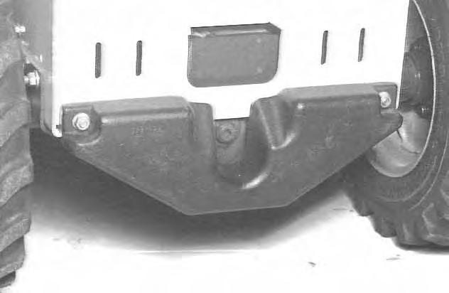
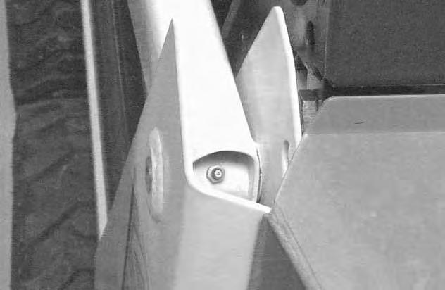
Pivot Pins
All pivot pins, lift arms and cylinders have a large pin held in position with lockbolts and retainer (Item 1) [A] & [B]
Check that the lockbolts are tightened to 8–10 ft.–lbs. (11–13 Nm) torque.
Do not over–tighten.
BOB–TACH
Inspection And Maintenance
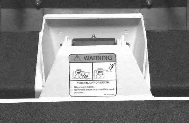
Move the Bob–Tach lever to engage the wedges[C]. The levers and wedges must move freely.
The wedges must extend through the holes in the attachment mounting frame (Item 1) [D].
Bob–Tach wedges must extend through the holes in attachment. Lever(s) must be fully down and locked. Failure to secure wedges can allow attachment to come off and cause injury or death.
W–2102–0497
Inspect the mounting frame on the attachment and the Bpb–Tach, linkages and wedges for excessive wear or damage. Replace anyu parts that are damaged, bent, or missing. Keep all fasteners tight.
Look for cracked welds. Contact your Bobcat dealer for repair or replacement parts.
Lubricate the wedges (See SERVICE SCHEDULE,Page 29 and LUBRICATION OF THE BOBCAT LOADER, Page 52.)