10 minute read
STARTING THE ENGINE


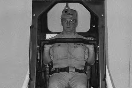
WRONG
When an engine is running in an enclosed area, fresh air must be added to avoid concentration of exhaust fumes. If the engine is stationary, vent the exhaust outside. Exhaust fumes contain odorless, invisible gases which can kill without warning.
W–2050–1285
AVOID INJURY OR DEATH
• Engines can have hot parts and hot exhaust gas. Keep flammable material away.
• Do not use machines in atmosphere containing explosive gas.
W–2051–1086
Normal Starting
Adjust the seat position for comfortable operation of the foot pedals and steering levers.
Fasten the seat belt snugly and adjust it so the buckle is centered between your hips.
Lower the seat bar [C].
Be sure the parking brake is engaged.
STARTING THE ENGINE (Cont’d)
Normal Starting (Cont’d)
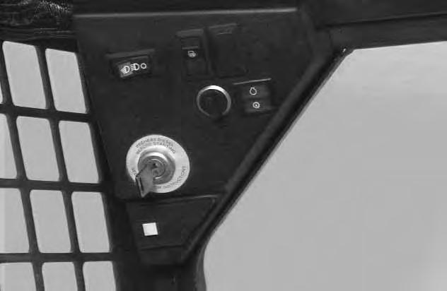
Put the foot pedals and steering levers in NEUTRAL POSITION (center) (Item 1) [A]
Set the engine speed control to 1/2 SPEED position(Item 2) [A]
Turn the key to the ON POSITION. The engine and transmission warning light will be ON when the key is on and the engine is stopped (Item 3) [A]
Turn the key to START POSITION (Item 4) [A] and release it when the engine starts. The key will return to the RUN POSITION (Item 5) [A].
Do not engage the starter for longer than 15 seconds at a time. Longer use can damage the starter by overheating. Cool the starter for one minute between uses.
I–2034–0284
STOP THE ENGINE IF THE WARNING LIGHTS DO NOT GO OFF.
NOTE:Upon failed start, if the key is turned OFF, wait for at least three seconds before turning the key ON to reset the fuel timer module.
Keep your hands on the steering levers and feet on the pedals while seated in the loader.
Do not use ether with glow plug (preheat) systems. Explosion can result which can cause injury or death.
Cold Temperature Starting
See Normal Starting Page 15. Turn the key switch to the RUN POSITION.
Push the preheat button (Item 1)[A] on the left side of the instrument panel to preheat the glow plugs.
Refer to the decal on the left side of the operator cab for operation of the preheat system [B]
Follow the steps under Normal Starting and repeat the preheating procedure until the engine starts.
If the temperature is below 32oF (0oC), use the following procedure to make starting the engine easier:
• Replace the engine oil with the correct type and viscosity for the anticipated starting temperature. (See Oil Chart Page 42.)
• Make sure the battery is at full charge.
• Install engine heater.
Warming The Hydraulic/Hydrostatic System
Let the engine run for a minimum of 5 minutes to warm the engine and hydrostatic transmission fluid before operating the loader.
If the warning light comes ON when operating the loader (cold), more warm up time is needed.
Stopping The Engine
Pull the engine speed control fully backward to decrease the engine RPM.
Turn the key switch to the OFF position.
Attachments And Buckets
Never use attachments or buckets which are not approved by Melroe Company. Buckets and attachments for safe loads of specified densities are approved for each model. Unapproved attachments can cause injury or death.
The dealer can identify, for each model loader, the attachments and buckets approved by Melroe Company. The buckets and attachments are approved for rated operating capacity and for secure fastening to the Bob–Tach.
The rated operating capacity for this loader is shown on a label in the operator cab. (SeeSPECIFICATIONS Page 69.)
Rated operating capacity is determined by using a standard dirt bucket, and material of normal density, such as dirt or dry gravel. If longer buckets are used the load center moves forward and reduces the rated operating capacity. If very dense material is loaded, the volume must be reduced.
Exceeding the rated operating capacity can cause the following problems [A]:
1.Steering the loader may be difficult.
2.Tires may wear faster.
3.There will be a loss of stability.
4.The life of the Bobcat loader will be reduced.
Use the correct size bucket for the type and density of material being handled. For safe handling of materials and avoiding machine damage, the attachment (or bucket) should handle a full load without going over the rated operating capacity for the loader. Partial loads make steering more difficult.
Installation And Removal (Without Bob–Tach)
The Bobcat is standard equipped with pin–type installation of attachments.
Install the pivot pins into the lower pivot holes in the bucket (Item 1) [B]. Align pins with holes in lift arms.
Use long bolt to pull the pins into the lift arms. Remove long bolts and install correct bolt. Tighten to 65–70 ft.–lbs. (88–94 Nm) torque (Item 2) [B]
Install the pin into the upper pivot hole in the bucket and the rod end of the tilt cylinder (Item 1) [C]
Install the retainer and bolt (Item 2) [C]. Tighten bolt to 8–10 ft.–lbs. (10–13 Nm) torque.
Reverse procedure to remove attachment.
Avoid Injury Or Death
Do not exceed rated operating capacity. Excessive load can cause tipping or loss of control.
ATTACHMENTS AND BUCKETS (Cont’d)
Installation And Removal (With Bob–Tach)
The Bob–Tach is used for fast changing of buckets and attachments. See the Attachment Operation & Maintenance Manual to install other attachments.
Bob–Tach levers have spring tension. Hold lever tightly and release slowly. Failure to obey warning can cause injury.
W–2054–1285
Pull the Bob–Tach levers all the way up (Item 1) [A]. Enter the loader.
Fasten the seat belt, lower the seat bar and start the engine.
Release the parking brake.
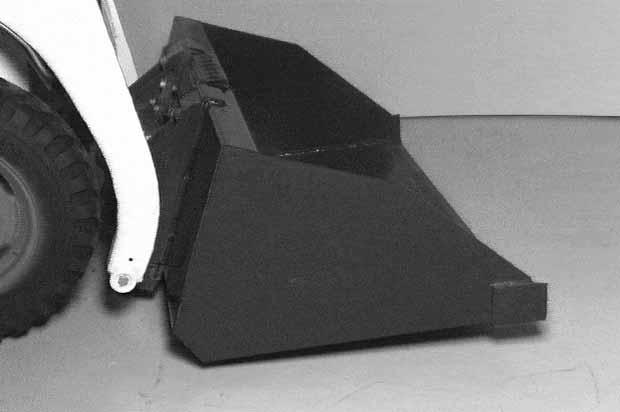
Lower the lift arms and tilt the Bob–Tach forward.
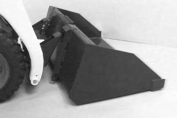
Drive the loader forward until the top edge of the Bob–Tach is completely under the top flange of the bucket [A] (or other attachments).
Be sure the Bob–Tach levers do not hit the bucket.
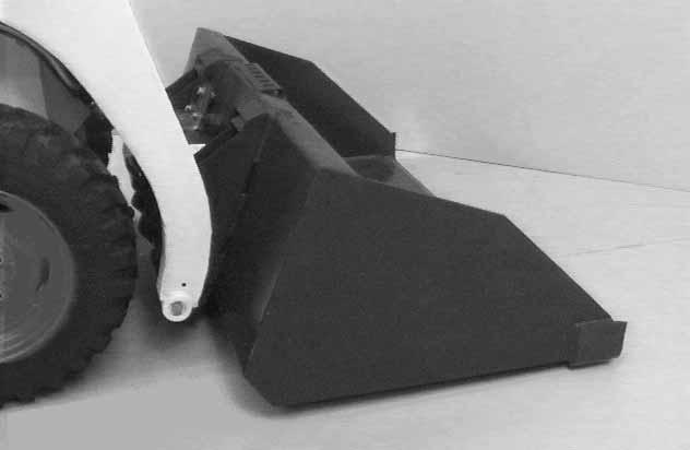
Tilt the Bob–Tach backward until the cutting edge of the bucket (or other attachment) is slightly off the ground [B]
Stop the engine and exit the loader.
Avoid Injury Or Death
Before you leave the operator’s seat:
• Lower the lift arms, put the attachment flat on the ground.
• Stop the engine.
• Engage the parking brake.
• Raise seat bar, move pedals until both locked.
W–2045–1086
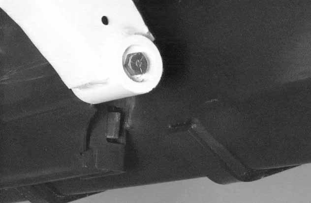
Push down on the Bob–Tach lever until it is fully engaged in the locked position [C]
If the levers do not engage in the locked position, see your Bobcat loader dealer for maintenance.
ATTACHMENTS AND BUCKETS (Cont’d)
The wedges (Item 1) [A] must extend through the holes in the mounting frame of the bucket (or attachment), securely fastening the bucket to the Bob–Tach. The wedge is shown extending through the hole in the bucket [A]
Bob–Tach wedges must extend through the holes in attachment. Levers must be fully down and locked. Failure to secure wedges can allow attachment to come off and cause injury or death.
Put the attachment flat on the ground and lower or close the hydraulic equipment. If the attachment is hydraulically controlled (ie: combination bucket, backhoe, etc.), stop the engine and relieve hydraulic pressure in the auxiliary circuit. (See Relieving Hydraulic Pressure, Page 11).
Raise the seat bar, unfasten the seat belt, set theparking brake and exit the loader.
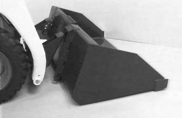
Pull the Bob–Tach levers [C] all the way up.
Disconnect the hydraulic hoses, if necessary. Enter the loader.
Fasten the seat belt, lower the seat bar and start the engine
Release the parking brake.
Lower the lift arms and tilt the Bob–Tach forward. Move the loader backward, away from the bucket or attachment [C]
Operating Procedure
When operating on a public road or highway, always follow local regulations. For example: Slow Moving Vehicle Sign or directional signals may be required. Always warm up the engine and hydrostatic system before operating the loader.
WITH BUCKET FULL
Machines warmed up with moderate engine speed and light load have longer life.
I–2015–0284
Operate the loader with the engine at full speed for maximum horsepower. Move the steering levers only a small amount to operate the loader.
New operators must operate the loader in an open area without bystanders. Operate the controls until the loader can be handled at an efficient and safe rate for all conditions of the work area.
With a full bucket, go up or downthe slope with the heavy end toward the top of the slope [A] & [B]
Going Down Slope
WITH BUCKET FULL
B–14306
With empty bucket, go down or up the slope with the heavy end toward the top of the slope [C] & [D].
Going Up Slope
WITH BUCKET EMPTY
B–09043
AVOID INJURY OR DEATH
• Keep the lift arms as low as possible.
• Do not travel or turn with the lift arms up.
• Turn on level ground.
• Go up and down slopes, not across them.
• Keep the heavy end of the machine uphill.
• Do not overload the machine.
Failure to obey warnings can cause the machine to tip or roll over and cause injury or death.
W–2018–1187
Raise the bucket only high enough to avoid obstructions on rough ground.
Going Down Slope
WITH BUCKET EMPTY
B–09042
Going Up Slope
B–09042
OPERATING PROCEDURE (Cont’d)
Filling The Bucket
Push down on the top of the lift pedal until the lift arms are all the way down. Push the top of the tilt pedal to put the cutting edge of the bucket on the ground [A].
Drive slowly forward into the material. Push the bottom of the tilt pedal to raise the front of the bucket [B]
Load, unload and turn on flat level ground. Do not exceed rated operating capacity shown on sign (decal) in cab. Failure to obey warnings can cause the machine to tip or roll over and cause injury or death.
W–2056–1187
Drive backward away from the material.
Emptying The Bucket
Push down on the bottom of the lift pedal to raise the lift arms. Push the top of the tilt pedal while raising the lift arms to level the bucket or attachment and help prevent material from falling off the back of the bucket or attachment.
Drive forward slowly until the bucket is over the top of the truck box or bin. Push the top of the tilt pedal until the bucket is empty [C]. If all the material is near the side of the truck or bin, push it to the other side with the bucket.
Never dump over an obstruction, such as a post, that can enter the operator cab. The machine could tip forward and cause injury or death.
W–2057–0694
OPERATING PROCEDURES (Cont’d)
Digging Into The Ground
Put the lift arms all the way down. Push the top of the tilt pedal until the cutting edge of the bucket is on theground. Drive forward slowly and continue to tilt the bucket down until it enters the ground [A]
Push the bottom of the tilt pedal a small amount to increase traction and keep an even digging depth [B]
Continue to drive forward until the bucket is full. Whenthe ground is hard, raise and lower the cutting edge of the bucket with the tilt pedal while driving forward slowly.
Push the bottom of the tilt pedal to tiltthe bucket backward as far as it will go when the bucket is full [C]
OPERATING PROCEDURES (Cont’d)
Leveling The Ground (Using Lift Arms In Float Position)
Push the top (toe) of the lift pedal all the way forwarduntil the pedal is in the locked position to put the liftarms in float position [A]
Push the tilt pedal to change the position of the cutting edge on the bucket. With the bucket tilted farther forward, there is more force on the cutting edge and more loose material can be moved.
Never drive forward when the hydraulic control for lift arms is in float position.
I–2005–1285
Drive backward to level loose material.
Push the bottom of the lift pedal to unlock from the float position.
Backfilling
Lower the lift arms and put the cutting edge of the bucket on the ground.
Drive forward to the edge of the hole to push the material into the hole [B].
Tilt the bucket forward as soon as it is past the edge of the hole [B].
If necessary, raise the lift arms to empty the bucket.
PARKING THE BOBCAT LOADER
Stop the Bobcat loader on level ground.
Lower the lift arms fully and put the edge of the bucket on the ground.
Pull the throttle all the way backward. Turn the key switch to the OFF POSITION.
Engage the parking brake.
Lift the seat bar and make sure the foot pedals are in the locked position.
Unbuckle the seat belt. Remove the key from the switch to prevent operation of the loader by unauthorized personnel.
Avoid Injury Or Death
Before you leave the operator’s seat:
• Lower the lift arms, put the attachment flat on the ground.
• Stop the engine.
• Engage the parking brake.
• Raise seat bar, move pedals until both lock. W–2045–1086
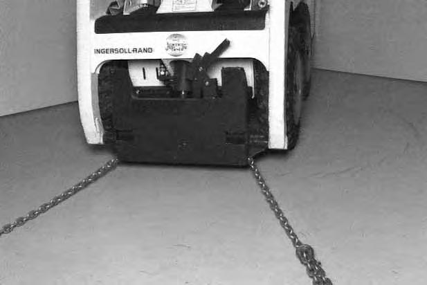
Transporting The Bobcat Loader
A loader with an empty bucket or no attachment must be loaded backward onto the transport vehicle [A]
The rear of the trailer must be blocked or supported [A] when loading or unloading the loader to prevent the front end of the trailer from raising up.
Use the following procedure to fasten the Bobcat loader to the transport vehicle to prevent the loader from moving during sudden stops or when going up and down slopes.
Fully lower any bucket or attachment. Stop the engine. Engage the parking brake.
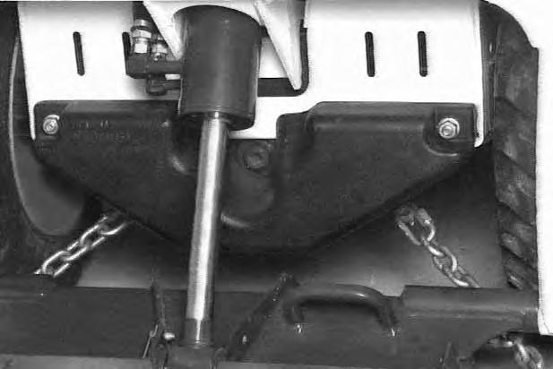
Fasten chains at the front using the slots in the axle gussets [B]. Counterweight is removed (Inset) to show clarity. DO NOT operate with counterweight removed.
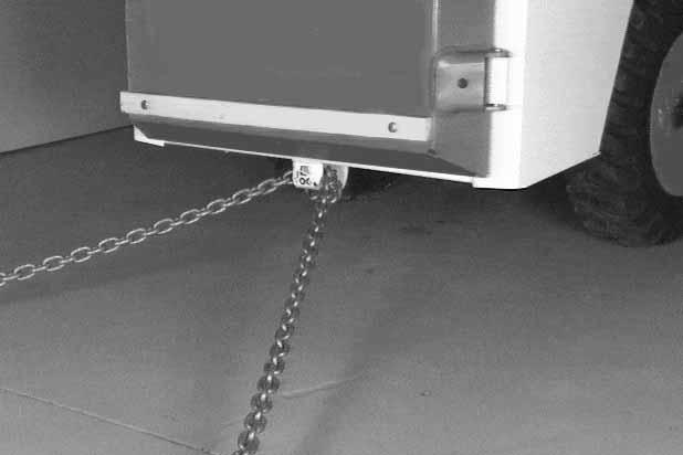
Fasten the rear of the loader as shown with a loop of chain through the tie down provided [C]
Stopping The Bobcat Loader
When the steering levers are moved to the neutral position, the hydrostatic transmission will act as aservice brake and stop the loader.
Avoid Injury Or Death
• Before lifting, check fasteners on single point lift and operator cab.
• Assemble front cab fasteners as shown in this manual.
• Never allow riders in the cab or bystanders within 15 feet (5 meters) while lifting the machine.
The loader can be lifted with the single point lift which is available as a kit from your Bobcat loader dealer.
Install the kit and lift the loader as shown [A]
The single point lift, supplied by Melroe Company is designed to safely lift and support the Bobcat loader without affecting roll over and falling object protection features of the operator cab.
Towing The Loader
To prevent damage to the loaders hydrostatic system, the loader must be towed only a short distance at slow speed. (Example: Moving the loader onto a transport vehicle).
Relief valve release tool set MEL1220 is available from your dealer. Tool must be installed before towing.
Raise the operator cab. (See Page 32 for the correct procedure.)
Clean the area around the hydrostatic pumps. Remove the high pressure relief valve from one side of each hydrostatic pump [B] and install the relief valve tubes. Install the plugs and tighten.
The towing chain (or cable) must be rated at 1–1/2 times the weight of the loader. (See SPECIFICATIONS Page 69.)
Turn the key switch to ON and press the traction lock override button.
Tow the Bobcat at 2 MPH (3,2 km/hr) or less for not more than 25 feet (7,6 meters).
If the electrical system is not functioning, contact your Bobcat loader dealer. (Part of the brake system must be disassembled to move the loader.)
Do not push or pull the machine at more than 2 MPH (3,2 km/h) or for a distance of more than 25 feet (7,6 meters) with the towing tool in place.