5 minute read
Connectors and Terminals


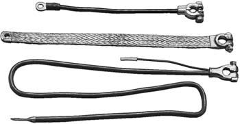
Figure 6-11. Assorted battery cables.
years, however, high-resistance, non-metallic cables have replaced metallic conductor cables as original equipment on cars and light trucks. Although metallicconductor ignition cables arestill made, they are sold for special high-performance or industrial applications and are not recommended for highway use. The conductors used in high-resistance, nonmetallic ignition cables are made of carbon, or of linen or fiberglass impregnated with carbon. These cables evolved for the following reasons: • High-voltage ignition pulses emit high-frequency electrical impulses or radio frequency interference (RFI) that interfere with radio and television transmission, as described in
Chapter 2. The principal method used to limit this interference is the use of high-resistance ignition cables, often referred to as suppression cables. • The extra resistance in the cable decreases the current flow and thus reduces the burning of spark plug electrodes. The higher resistance also helps take advantage of the high-voltage capabilities of the ignition system, as shown in Part Five of this manual.
The high-voltage current carried by ignition cables requires that they have much thicker insulation than low-voltage primary wires. Ignition cables are 7 or 8 millimeters in diameter, but the conductor in the center of the cable is only a small core. The rest of the cable diameter is the heavy insulation used to contain the high voltage and protect the core from oil, dirt, heat, and moisture. One type of cable insulation material is known by its trade name, Hypalon, but the type most commonly used today is silicone rubber. Silicone is generally thought to provide greater high-voltage insulation while resisting heat and moisture better than other materials. However, silicone insulation is softer and more pliable than other materials and thus more likely to be torn or damaged by rough handling. Cables often have several layers of insulation over the conductor to provide the best insulating qualities with strength and flexibility.
Electrical circuits can be broken by the smallest gap between conductors. The gaps can be caused by corrosion, weathering, or mechanical breaks. One of the most common wear points in an automobile electrical system is where two conductors have been joined. Their insulation coats have been opened and the conductive material exposed. Special connectors are used to provide strong, permanent connections and to protect these points from wear.
These simple connectors are usually called wiring terminals. They are metal pieces that canbe crimped or soldered onto the end of a wire. Terminals are made in many shapes andsizes for the many different types of connections required. They can be wrapped with plastic electrical tape or covered with special pieces of insulation. The simplest wire terminalsjoin a single wire to a device, to another single wire, or to a few other wires (Figure 6-12). Terminals for connecting to a device often havea lug ring, a spade, or a hook, which can bebolted onto thedevice. Male and female spade terminals or bullet connectors are often used to connect two individual wires
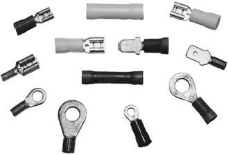
Figure 6-12. Some common single-wire terminals (connectors).
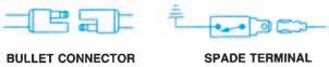
Figure 6-13. Male and female bullet connectors and spade terminals are common automotive connectors.
(DaimlerChrysler Corporation)
(Figure 6-13). For more information about the use of different types of connectors, see the “Connector Repair” section in Chapter 6 of the Shop Manual.
Multiple Wire Connectors
Although the simple wiring terminals just described are really wire connectors, the term connector is normally used to describe multiple-wire connector plugs. This type of plug is used to connect wiring to switches, as shown in Figure 6-14, or to other components. It also is used to join wiring harnesses.
Multiple-wire connectors are sometimes called junction blocks. On older vehicles, a junction block was a stationary plastic connector with terminals set into it, in which individual wires were plugged or screwed in place. Because of the time required to connect this type of junction block on the assembly line, it has been replaced by a modem version that accepts several plugs from different harnesses (Figure 6-15).
Some multiple-connector plugs have as many as 40 separate connections in a single plug. They provide a compact, efficient way to connect wiresfor individual circuits while still grouping them together in harnesses. Wiring connections can be made quickly and accurately with multiple connectors, an important consideration in assembly-line manufacturing.
Figure 6-14. Multiple connectors are used to make
complex switch connections. (DaimlerChrysler Corporation)
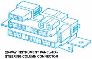
Figure 6-15. This junction block accepts individual wires on one side and connectors on the other.
(DaimlerChrysler Corporation)
Figure 6-16. Connectors have some form of lock to prevent accidental separation. Individual terminals and wires can be removed from some connectors; other connectors are replaced as an entire assembly.
(GM Service and Parts Operations)
Such connector plugs generally have hard plastic shells, with one half of the connector containing the male terminals or pins, and the other half containing the female terminals or sockets. Probing the rear of the individual connections without separating the connector can test circuit operation. Alocking tab of some type is used to prevent the connector halves from separating. Separation or removal of the plug may require the locking tab to be lifted or depressed (Figure 6-16).
Although many hard-shell connector designs allow removal of the individual wires or their terminals for repair, as shown in Figure 6-17, manufacturers are now using plugs that are serviced as an assembly. If a wire or terminal is defective, the entire plug is cut from the harness. The replacement plug is furnished with 2 or 3 inches of wires extending from the rear of the plug. These plugs are designed to be replaced by matching and soldering their wire leads to the harness.
Bulkhead Connectors
A special multiple connector, called a bulkhead connector or bulkhead disconnect, is used where a
Figure 6-17. A bulkhead connector, or disconnect, is mounted on many firewalls. Multiple-wire connectors plug
into both sides. (DaimlerChrysler Corporation)


