12 minute read
Heating and Air-Conditioning Systems


Although heating and air-conditioning systems rely heavily on mechanical and vacuum controls, a gooddeal of electrical circuitry also is involved. Since the late 1970s, air-conditioning systems havebecome increasingly “smart,” relying on solidstate modules or microprocessors for their operation. This also has complicated the job of servicing such systems.
Heater Fan
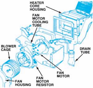
Heating systems use a heater fan attached to a permanent-magnet, variable-speed blower motor to force warm air into the passenger compartment (Figure 15-1). The higher the voltage applied to the motor, the faster it runs. Aswitch mounted on the instrument panel controls the blower operation (Figure 15-2). In most heating systems, the switch controls blower speed by directing the motor ground circuit current through or around the coils of a resistor block (Figure 15-3) mounted near the motor.
When the switch is off, the ground circuit is open and the blower motor does not run. (Some systems used in the 1970s, however, were wired so that the blower motor operated on low speed whenever the ignition was on). When the switch is turned to its low position, voltage is applied across all of the resistor coils and the motor runs at a low speed. Moving the switch to the next position bypasses one of the resistor coils. This allows more current to the blower motor, increasing its speed. When the switch is set to the highest position, all of the resistors are bypassed and
Figure 15-1. An electric motor drives the heater fan. Figure 15-2. The fan control switch routes current through paths of varying resistance to control motor
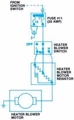
speed. (DaimlerChrysler Corporation)
Figure 15-3. Blower motor resistors are installed on a “block” near the motor. Some resistor blocks have a thermal limiter.
full current flows to the motor, which then operates at full speed.
In some GM systems, a relay is used between the high switch position and the blower motor. Ford incorporates a thermal limiter in its resistor block, as shown in Figure 15-3. Current flows through the limiter at all blower speeds. If current passing through the limiter heats it to 212 F (100 C), the limiter opens and turns off the blower motor. When this happens, the entire resistor block must be replaced.
Air-Conditioning Fan andCompressor Clutch
Air-conditioning fan controls are similar to heater controls. In most cars that have both heating and air-conditioning systems, the same blower motor is shared by both systems (Figure 15-4). One or more switches route current through different resistors to control the blower motor speed.
In addition to the fan switch, the control assembly in the passenger compartment contains a driver-controlled air-conditioning clutch switch and an integral clutch switch activated when the function selector lever is set to the defrost position. These switches are used to operate the belt-driven compressor. Acompressor that operates constantly wastes energy. To use energy more efficiently, the compressor has anelectromagnetic clutch (Figure 15-5). This clutch locks and unlocks the compressor pulley with the compressor shaft. The compressor will operate only when the clutch switch is closed and the electromagnetic clutch is engaged.
Most recent air-conditioning systems use a clutch-cycling pressure switch or a pressurecycling switch to control compressor clutch operation. This pressure-operated electric switch generally is wired in series with the clutch field
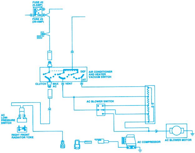
Figure 15-4. The AC system and heater system share the same fan. (DaimlerChrysler Corporation)
coil. The switch closes when the pressure on thelow side of the refrigerant system rises to a specified value, engaging the clutch. When system pressure drops to a predetermined value, the switch opens to shut off the compressor. Theswitch operates to control evaporator core pressure and prevent icing of the evaporator cooling coils.
Air-conditioning systems may also use lowand high-pressure switches as safety devices, asfollows: • The low-pressure switch is closed during normal compressor operation and opens only when refrigerant is lost or ambient temperature is below freezing. • The high-pressure switch is normally closed to permit compressor operation.
However, if system pressure becomes excessive (generally 360–400 psi or 2,480–2,760 kPa), the switch acts as a relief valve and opens to shut off the compressor.
Once pressure drops to a safe level, the switch will close again and permit the compressor to operate.
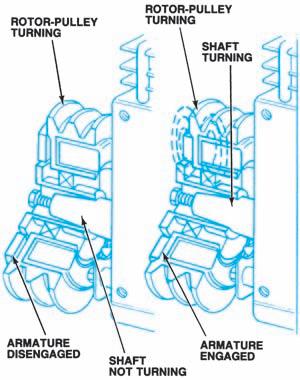
Figure 15-5. The electromagnetic clutch in this airconditioning compressor prevents the compressor from wasting energy. • A pressure relief valve on the compressor high-pressure side may be used instead of a high-pressure switch. Some systems have a diode installed inside the compressor clutch connector to suppress any voltage spikes that might be produced by clutch circuit interruption.
Other compressor clutch controls may include the following:
• A power-steering pressure or cutout switch to shut the compressor off whenever high power-steering loads are encountered, as during parking. The switch senses line pressure and opens or closes the circuit to the compressor clutch accordingly. • A wide-open throttle (WOT) switch on the throttle body or accelerator pedal to open the circuit to the compressor clutch during full acceleration. • A pressure-sensing switch in the transmission to override the WOTswitch when the transmission is in high gear.
Temperature Control
The basic electrical components of most airconditioning systems have already been described. As we have seen, they provide input to, and protection for, the refrigeration system.

Figure 15-6. Manual air conditioning system block
diagram. (GM Service and Parts Operations)
All input to the air-conditioning system begins with the control assembly mounted in the instrument panel. Temperature control can take the following forms:
• Manual control • Semiautomatic control (programmer controlled) • Fully automatic control (microprocessor or body computer controlled)
A manual temperature control system does notprovide a method by which the system can function on its own to maintain a preset temperature. The user, through the mechanical control assembly, must make system input. Once the air-conditioning switch is turned on, the temperature selection made, and the blower speed set, the system functions with vacuum-operated mode door actuators and a cable-actuated airmix door. Figure 15-6is a block diagram of such a system.
Automatic Temperature Control (ATC)
With a semiautomatic temperature control system, the user still selects the mode but the actuators are electrically operated. Selecting themode does not directly control the actuator; itcreates an electrical input to an independentmodule or programmer (Figure 15-7). OnChrysler vehicles, the electronic servomotor performs the programmer function (Figure 15-8). Two sensors are added to informthe programmer of ambient temperature and in-car temperature (Figure 15-9). The programmer calculates the resistance values provided by the temperature dial setting and the two additional sensors
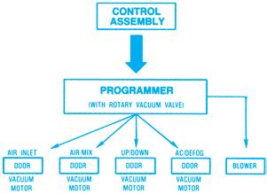
Figure 15-7. Semiautomatic AC systems use an electronic programmer to translate mechanical control movement into actuator signals. (GM Service and Parts
Operations)
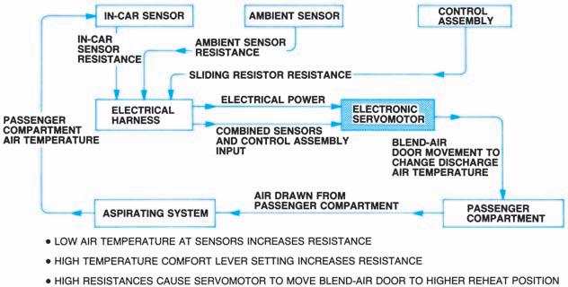
Figure 15-8. An electronic servomotor takes the place of a programmer in DaimlerChrysler’s semiautomatic AC
system. (DaimlerChrysler Corporation)
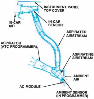
Figure 15-9. Resistance values from in-car and ambient temperature sensors are coupled with the resistance provided by the control assembly temperature dial to
direct the programmer. (GM Service and Parts Operations)
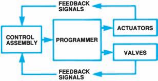
Figure 15-10. The actuators used in fully automatic AC systems provide feedback signals that allow the control assembly to monitor system operation. (GM
Service and Parts Operations)
and adjusts cables or vacuum selector valves to maintain the preset temperature. Thesemiautomatic temperature control systemdiffers from a manual system primarily intheuse of the programmer; actuators and doorsare still moved by mechanical linkage andcables.
In a fully automatic temperature control system, the control assembly is electronic instead of manual. The user selects the mode and the temperature. The control assembly microprocessor sends the appropriate signals to the programmer to operate the system. Electric servomotors are used as actuators to send a feedback signal to the electronic control assembly (Figure 15-10). This lets the control assembly monitor the system and make whatever adjustments are required to maintain the desired system temperature.
Since the control assembly is constantly monitoring the system, it knows when a malfunction occurs and can transmit this information to the service technician.
Semiautomatic Control (Programmer Controlled)
The GM C61 system is representative of a semiautomatic control system. Once the user hasselected the mode and temperature, the system automatically controls blower speed, air temperature, air delivery, system turn-on, and compressor operation. It does this with a programmer inserted between the control assembly and the actuators (Figure 15-7), as well as two temperature sensors. The ambient sensor installed in the programmer is exposed to ambient airflow through a hole in the module wall; the in-car sensor is located under the instrument panel top cover. Figure 15-9shows the sensor locations. Both sensors are disc-type thermistors that provide a return voltage signal to theprogrammer based on variable resistance. Theprogrammer is built into the air-conditioning control assembly (Figure 15-11) and contains the following: • A DC amplifier that receives a weak electrical signal from the sensors and control assembly and sends a strong output signal proportional to the input signal it receives • A transducer that converts the amplifier signal to a vacuum signal that actuates the vacuum motor • A vacuum checking relay that has a check valve to maintain a constant vacuum signal to the vacuum motor and the rotary vacuum valve • A vacuum motor to actuate the rotary shaft that drives the air-mix door link • A rotary vacuum valve to route vacuum to control the mode doors and operate the heater water valve; this valve does the same job as a vacuum selector valve in a manual system
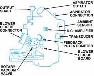
Figure 15-11. Components of the programmer used in GM’s C61 AC system. (GM Service and Parts
Operations)
• A feedback potentiometer to inform the programmer of system corrections required by changing temperature demands A circuit board electrical switch is mounted on the base of the control assembly. The rotary switch contacts are positioned by the mode-select lever to provide the correct electrical path to the compressor clutch. The temperature dial varies the resistance of a wire-wound rheostat installed directly above it. The programmer uses the total resistance provided by the temperature dial and temperature sensors to calculate how the system should function.
To use this type of system, the driver need only set the control assembly in the auto mode and select a temperature. From this point on, the programmer controls the system operation by automatically setting the mode and blower speed and adjusting the air-mix doors to maintain the desired air temperature. Note that we have added nothing to the underhood portion of the air-conditioning system; we have only modified the operation of the control system by adding a device to maintain temperature within a selected narrow range.
Fully Automatic Control (BCM Controlled)
The electronic climate control (ECC) system used by Cadillac (Figure 15-12) is similar to the ETCC system just described. When used with a body control computer (BCM), the control assembly contains an electronic circuit board, but the BCM acts as the microprocessor. The BCM is constantly in touch with the climate control panel on the control assembly through a data link, or digital signal path (serial data line) provided for communication. The panel transfers user requests to the BCM, which sends the correct data to the panel for display.
Like the other semiautomatic and fully automatic systems we have looked at, the user selects the mode and temperature. The system automatically controls blower speed, air temperature, air delivery, system turn-on, and compressor operation. Although the ECC system functions similarly to the ETCC system, there are differences in compressor cycling methods. In a system without BCM control, the compressor clutch is grounded through the low-pressure switch. The power module thus cycles power tothe compressor clutch (Figure 15-14A). In a BCM-controlled system, the compressor clutch current is received through a fuse and the power steering cutout switch or diode; the power module cycles the ground circuit for the compressor, Figure 15-14B.
The electronic comfort control (ECC) system used by Oldsmobile is BCM controlled and canbe used as either a fully automatic or a manual system. When used manually, the driver can control blower speed and air delivery mode,but the system will continue to control temperature automatically. In addition to the BCM, power module, programmer, and control panel assembly used in other BCM-controlled systems, the ECC system uses inputs from the engine (electronic) control module (ECM). This allows the BCM to check several engine andcompressor conditions before it turns the compressor on.
The BCM communicates with the ECM, the ECC panel, and the programmer on the serial data line to transmit data serially (one piece after another). The serial data line acts like a party telephone line; while the BCM is communicating with the ECM, the programmer and the ECC panel can “hear” and understand the conversation. They also can process and use the information communicated, but they cannot cut in on the transmission. For example, suppose the ECM is sending engine data to the BCM. The ECC panel computer, which needs to display engine rpm to the driver, “listens” in on the conversation, picks
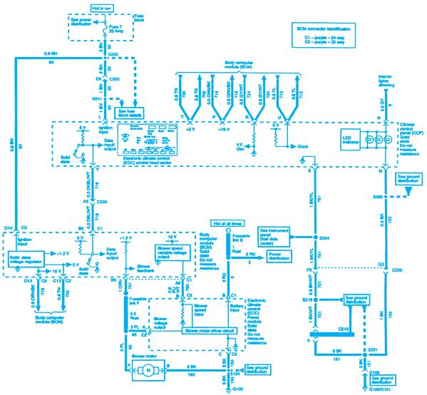
Figure 15-12. BCM-controlled HBAC system schematic. (GM Service and Parts Operations)
up the data it needs, and displays it on its panel. When the ECM is finished, it momentarily transmits a 5-volt signal to declare the line idle and the BCM opens a conversation with the next device it needs to talk with.
The programmer controls air delivery and temperature on instructions from the BCM, using a series of vacuum solenoids that control the mode door operation. The programmer also has a motor that controls the air-mix door position to regulate temperature. When directed to change blower speed by the BCM, the programmer sends a variable voltage signal to the power module, which sends the required voltage to the blower motor.
The ECC system is the most complex of the ones we’ve discussed, and this is reflected in the diagnostic sequence designed into the overall system network. When any subsystem exceeds its programmed limits, the system sets a trouble code andin some cases provides a backup function. Theinstrument panel cluster and the ECC panel (Figure 15-13) are used to access and control the self-diagnostic features. When the technician accesses the diagnostic mode, any stored BCM and ECM codes are displayed, along withvarious BCM and ECM parameters, discrete inputs and outputs, and any BCM outputoverride information.


