
6 minute read
Radios and Entertainment Systems


temperature is reached, the blower will stay on high speed and the air temperature actuators will stay in the full heat position. When the coldest position is selected in automatic operation, the blower will stay on high and the air temperature actuators will stay in the full cold position.
In cold temperatures, the automatic HVAC system will provide heat in the most efficient manner. The vehicle operator can select an extreme temperature setting but the system will not warm the vehicle any faster. In warm temperatures, theautomatic HVAC system will also provide airconditioning in the most efficient manner. Selecting an extreme cool temperature will not cool the vehicle any faster.
Entertainment radios (Figure 15-15) are available in a wide variety of models. The complexity of systems varies from the basic AM radio to the compact disc (CD) player with high power amplifiers and multiple speakers. However, the overall operation of the radio itself, electrically, is basically the same. The major components in a basic AM system are a radio receiver and speaker. In the more complex stereo systems, the major components are an AM/FM radio receiver, a stereo amplifier, a sound amplifier switch, several speakers, and possibly a power antenna system.
In addition, many of the newer designs utilize a control module to aid in system diagnostics, memory presets, and other advanced features. The use of a scan tool and the appropriate service manual will enable the technician to determine the correct repair.
The inner circuitry of radios, tape players, CD players, power amplifiers, and graphic equalizers is beyond the scope of this text. However, a technician must understand the external circuitry of sound systems in order to troubleshoot them. Most sound units and speakers are grounded. In a few four-speaker systems, the speakers are insulated from their mountings. Current flows from the sound unit, through all of the speakers, and back to ground.
Figure 15-15. Radio face panel.
Entertainment System Diagnostics
Internal diagnostic examination of the radio should be left to the authorized radio service center. However, the automotive technician should be able to analyze and isolate radio reception conditions to the area of the component causing the condition. All radio conditions can be isolated to one of five general areas: • Antenna system • Radio chassis (receiver) • Speaker system • Radio noise suppression equipment • Sound system
Radio Operation
Operation of the AM radio requires only that power from the fuse panel be available at the radio. The radio intercepts the broadcast signals with its antenna and produces a corresponding input to the system speaker. In addition, some radios have built-in memory circuits to ensure that the radio returns to the previously selected station when the radio or ignition switch is turned off and back on again. Some of these memory circuits require an additional power input from the fuse panel that remains hot at all times. The current draw is very small and requires no more power than a clock. However, if battery power is removed, the memory circuit has to be reset.
The service manual and owner’s guide for the vehicle contain detailed information concerning radio operation. If the radio system is not working, check the fuse. If the fuses are okay, refer tothe service manual. Remember, the radio chassis (receiver) itself should only be serviced by
a qualified radio technician or specialty radio service shop. If you determine that the radio itself is the problem, remove the radio and send it to a qualified radio technician.
Antitheft Audio Systems
Most radio systems have built-in devices that make the audio system soundless if stolen. If the power source for the audio system is cut, the antitheft system operates so that even if the power source is reconnected, the audio system will not produce any sound. Some systems require an ID number selected by the customer to be entered. When performing repairs on vehicles equipped with this system, the customer should be asked for the ID number prior to disconnecting the battery terminals or removing the audio system. After the repairs, the technician or customer must input the ID number to regain audio system operation.
Other systems sense a specific code from the control module to allow the audio system to operate. This means the radio will not operate unless it is installed in the correct vehicle. Always refer to the vehicle service manual before removing a stereo to determine if it is equipped with any antitheft devices and the procedures for removal.
Noise Suppression
The vehicle’s ignition system is a source of radio interference. This high-voltage switching system produces a radio frequency electromagnetic field that radiates at AM, FM, and CB frequencies. Although components have been designed into the vehicle to minimize this concern, the noise is more noticeable if the radio is turned slightly off channel when listening to FM programs. Vehicle electrical accessories and owner add-on accessories may also contribute to radio interference. Furthermore, many noise sources are external to the vehicle, such as power lines, communication systems, ignition systems of other vehicles, and neon signs.
In addition to resistance-type spark plugs and cables, automobiles use capacitors and ground straps to suppress radio static or interference caused by the ignition and charging systems. Capacitors may be mounted as follows: • Inside the alternator (Figure 15-16) • Behind the instrument panel, near the radio (Figure 15-17) • At the ignition coil with the lead connectedto the coil primary positive terminal (Figure 15-18A) • In a module mounted at the wiper motor and connected in series between the motor and wiring harness (Figure 15-18B)
Ground straps are installed to conduct small, high-frequency electrical signals to ground. They require a large, clean, surface-contact area. Such ground straps are installed in various locations depending upon the vehicle. Some common locations are as follows:
• Radio chassis to cowl • Engine to cowl • Across the engine mounts • From air-conditioning evaporator valve to cowl
The small bulb that lights the sound unit controls may be part of the instrument panel

Figure 15-16. RFI capacitors can be installed inside
the alternator. (DaimlerChrysler Corporation)
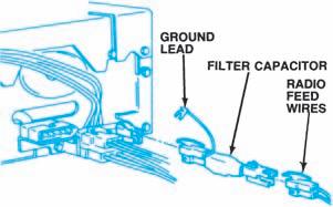
Figure 15-17. An RFI capacitor may be installed
near the radio. (GM Service and Parts Operations)
Figure 15-18. RFI capacitors may be installed onthe ignition coil or wiper motor. (DaimlerChrysler
Corporation)

Figure 15-19. The radio illumination bulb is controlled by the IP light circuit. (DaimlerChrysler
Corporation) Figure 15-20. The motor of an electrically extended radio antenna is usually installed inside the wheel well under a protective cover. (GM Service and Parts

Operations)
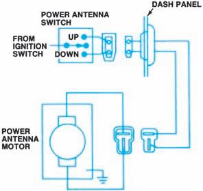
Figure 15-21. A separate switch can control power
antennas. (DaimlerChrysler Corporation)
circuitry (Figure 15-19) or part of the sound unit’s internal circuitry. Some cars use electrically extended radio antennas (Figure 15-20). The antenna motor may be automaticalIy activated when the radio is turned on, or a separate switch (Figure 15-21) may control it. Arelay may control current to the antenna motor.


