1 minute read
Replacing the LCD Module


1. Carefully align the LCD module over the hinge sockets and lower the module into the chassis, taking care not to trap the LCD cables.
2. Replace the two securing screws on the right hinge as shown.

Step
Size
LCD Module M2.5*5 2
Quantity Screw Type
4. Replace the two securing screws on the left hinge as shown.
Step
Size
LCD Module M2.5*5 2
Quantity Screw Type
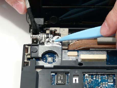
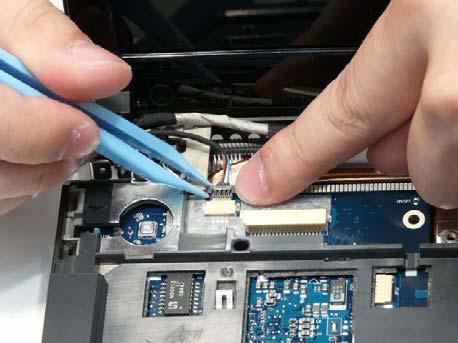
5. Reconnect the Microphone cable to the Mainboard as shown.

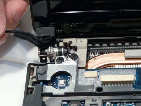
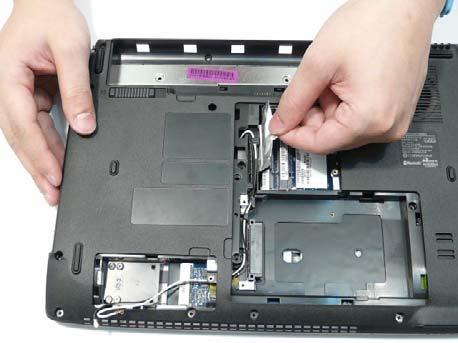
7. Insert the Antenna cables through the casing, as shown, and pull through from the underside.

NOTE: Ensure the cable is pulled completely through the casing. 8. Run the Antenna cables along the cable channel as shown, using all available cable clips.

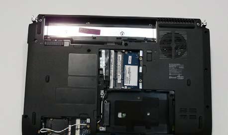
IMPORTANT: Run the cables as shown to avoid trapping when the Switch Cover is replaced.
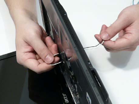
10. Pull the Antenna through the casing into the WLAN bay as shown.

11. Turn the computer over. Replace the two securing screws.
Step
Size
LCD Module M2.5*5 2