9 minute read
INTRODUCTION . . . . . . . . . . . . . . . . . . . . . . . . . . . . . . . . . . . . . .7


Figure 1–3. 2000 Product Family—Cross Section (with Park Pawl)
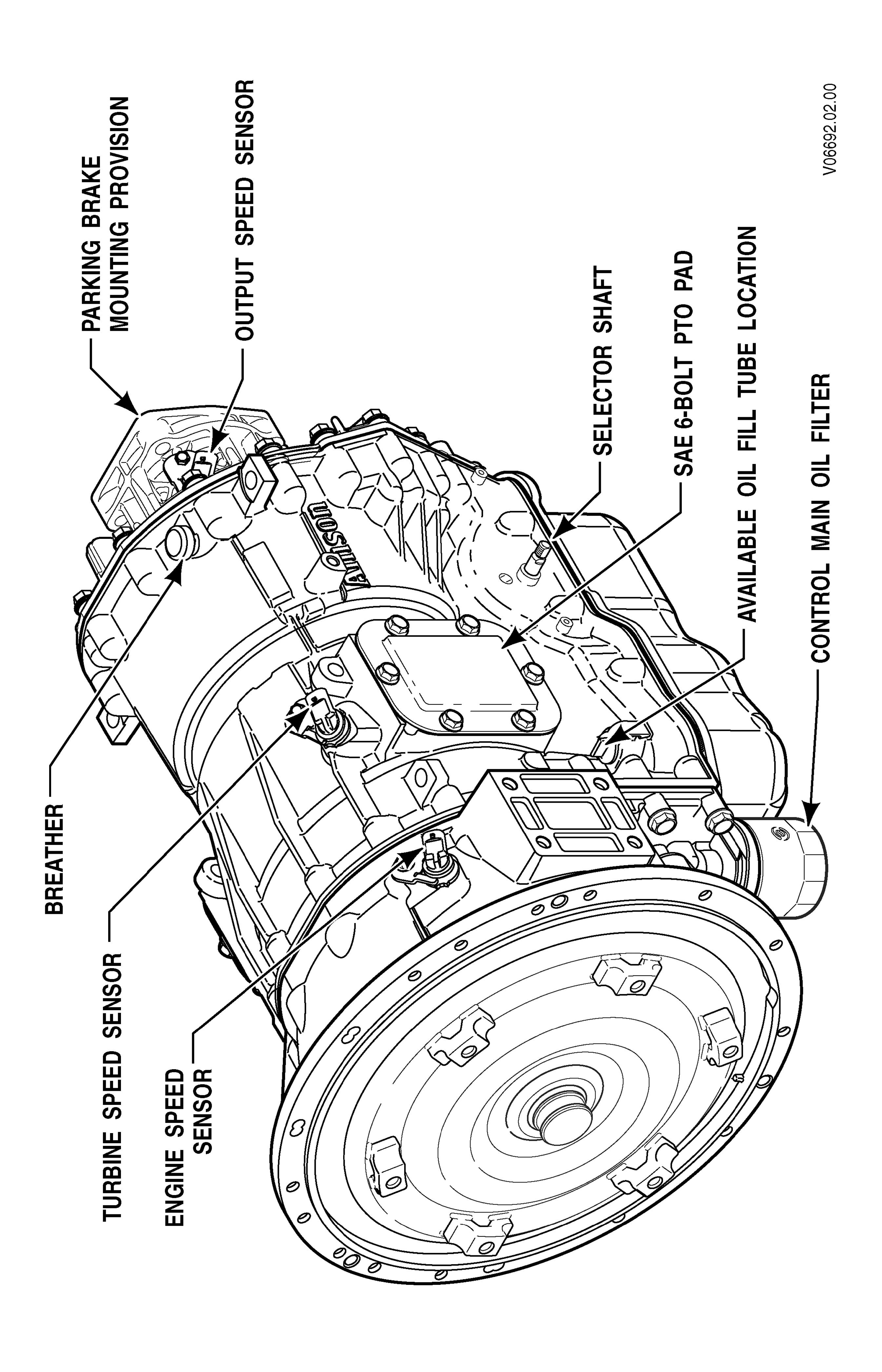
Figure 1–4. 1000 and 2000 Product Families—LeftFront V iew

Figure 1–5. 1000 and 2000 Product Families—RightRear V iew
PREVENTIVE MAINTENANCE Section
2–1. PERIODIC INSPECTION AND CARE
T ransmission Inspection.
CAUTION: When cleaning the transmission, not spray steam, water , cleaning solution directly the electrical connectors. Spraying steam, water , cleaning solution the electrical connectors can cause codes and cross talk.
CAUTION: When cleaning the transmission, not spray steam, water , cleaning solution directly the breather . Spraying steam, water , cleaning solution the breather can force water cleaning solution into the transmission and contaminate the transmission fluid.
Clean and inspect the exterior the transmission regular intervals. Severity service and operating conditions determine the frequency these inspections. Inspect the transmission for: • Loose bolts—transmission and mounting components. • Fluid leaks—repair immediately . • Loose, dirty , improperly adjusted throttle sensor • Damaged loose hoses. • W orn, frayed, improperly routed electrical harnesses. • W orn frayed electrical connectors. • W orn outofphase driveline Ujoints and slip fittings. • Clogged dirty breather (vent assembly).
V ehicle Inspection. Check the vehicle cooling system occasionally for evidence transmission fluid. T ransmission fluid in the vehicle cooling system indicates a faulty oil cooler .
W elding.
CAUTION: When welding the vehicle: • NOT WELD the vehicle without disconnecting from the
TCM all control system wiring harness connectors. • NOT WELD the vehicle without disconnecting TCM battery power and ground leads. • NOT WELD any control components. • NOT CONNECT welding cables any control components.
A label describing onvehicle welding precautions ST2067EN is available from your authorized Allison service dealer and should installed in a conspicuous place. A vehicle used in a vocation that requires frequent modifications repairs involving welding must have onvehicle welding label.
2–2. PROGNOSTICS
1000 and 2000 Product Families Service Prognostics. Service prognostics will available beginning with MY09 vehicles and is only fered a package the option the OEM (refer the caution for vehicles not equipped for Prognostics). The Service Prognostics package requires the use
Allisonapproved TES 295 fluids and P/N 29539579 Control Main filter . Prognostics are used predict the need for transmission maintenance. T ransmission operating parameters monitored the prognostics feature are:
Oil Life Monitor
Filter Life Monitor
T ransmission Health Monitor
NOTE: To determine if your vehicle has Prognostics enabled, observe operation the OEMinstalled service indicator light. This light will illuminate for five seconds during start in all equipped vehicles. When prognostics are enabled, the service indicator light will illuminate again for three seconds after the initial five second bulb check. you are still unable determine whether your vehicle has Prognostics enabled, consult with your OEM service department authorized Allison distributor dealer .
When a specified service threshold is detected for one these parameters, the TRANS SER VICE indicator is illuminated alert the operator the need for action. Failure attend the service condition and reset the
TRANS SER VICE indicator within a defined operating period will result in the illumination the CHECK TRANS light (in addition the TRANS SER VICE light), indicating the increased probability that the service condition may/will develop into a more serious condition. The process for resetting the TRANS SER VICE indicator varies for each feature and is described in each the following sections. The Allison DOC TM For PC–Service T ool may used review the current status any these features and a history indicator resets.
CAUTION: T ransmission Prognostics features may turned
OFF a special transmission calibration and REQUIRES the use Allisonapproved TES 295 fluids. any other fluids filters are used, prognostic features must turned OFF . Prognostics information will not accurate with any the use any other transmission fluids and could result in improper maintenance activities resulting in transmission damage. Prognostics is not programmed is turned OFF , refer the miles/hours/months fluid and filter change interval charts in the section this book, visit www .allisontransmission.com for a list Allisonapproved TES 295 fluids, read Service Tips 1099H for details.
Oil Life Monitor . The TRANS SER VICE indicator will illuminated, denoting a required change the transmission fluid, when the remaining fluid life reaches approximately 2 percent (the parameter begins 100 percent moving downward towards the lowest threshold). The TRANS SER VICE indicator will lit steadily upon each initialization the TCM, and will remain steady for approximately two minutes after the initial selection a drive range, until service is performed and the indicator is reset. The TRANS SER VICE indicator can reset with the Allison DOC TM For PC–Service T ool. may also reset selecting NDNDNRN the shift selector , pausing briefly (less than 3 seconds) between each selector movement, with the ignition and the engine not running. More details are provided in applicable Allison service literature for your specific transmission model. Failure perform maintenance and reset the TRANS SER VICE indicator within the next 100 hours transmission operation will result in the illumination the TRANS SER VICE light (in addition the TRANS SER VICE light). Any time this light is illuminated, the TCM will register a diagnostic code, which will require the use Allison DOC TM For PC–Service T ool clear the code.
addition viewing diagnostic codes, the Allison DOC TM For PC–Service T ool may also used display the amount transmission operation from the initial service indication until the service reset.
Filter Life Monitor . The TRANS SER VICE indicator will flash beginning with the first TCM initialization after reaching the time and mileage parameters, indicating that the filter has reached the end its designed life. The indicator will continue flash for two minutes after D (Drive) has been selected. Thereafter , the indicator will illuminate and flash upon each TCM initialization, continuing flash for two minutes after the selection D (Drive) each time, until service is performed and the indicator is reset. The TRANS SER VICE indicator can reset with the Allison DOC TM For PC–Service T ool. may also reset selecting NRNRNDN the shift selector , pausing briefly (less than 3 seconds) between each selector movement, with the ignition and the engine not running. More details are provided in applicable Allison service literature for your specific transmission model. Failure perform maintenance and reset the TRANS SER VICE indicator after additional 100 hours transmission operation will result in the illumination the CHECK TRANS light (in addition the TRANS SER VICE light). Any time this light is illuminated, the TCM will register a diagnostic code, which will require the use Allison DOC TM For PC–Service T ool clear the code. addition viewing diagnostic codes, the Allison DOC TM For PC–Service T ool may also used display the amount transmission operation from the initial service indication until the service reset.
T ransmission Health Monitor . The TRANS SER VICE indicator will illuminated, indicating the need for clutch maintenance, when the remaining clutch life reaches approximately percent, if the running clearance exceeds a maximum value which may indicate a nonwearrelated issue. The indicator will lit steadily upon initialization the TCM, and will remain steady all times, continuing operate in this manner until service is performed and the indicator is reset. reset does not occur within 100 hours, the CHECK TRANS light will illuminated (in addition the TRANS SER VICE light) and the TCM will register a diagnostic code. The indicator will reset automatically upon elimination the clutch clearance condition which initiated it. The indicator can also reset using the Allison DOC TM For PC–Service T ool if necessary . The Allison DOC TM For PC–Service T ool may used display the amount transmission operation from the initial service indication until the service reset.
2–3. IMPORT ANCE PROPER TRANSMISSION FLUID LEVEL
T ransmission fluid cools, lubricates, and transmits hydraulic power . Always maintain proper fluid level. fluid level is too low , the torque converter and clutches not receive adequate supply fluid and the transmission overheats. the level is too high, the fluid aerates—causing the transmission shift erratically and overheat. Fluid may expelled through the breather dipstick tube when the fluid level is too high.
2–4. TRANSMISSION FLUID CHECK
W ARNING: For vehicles containing 1000 and 2000 Product Families transmissions with park pawl, each time you park the vehicle leave the operator ’s station with the engine running, the following:
Bring the vehicle a complete stop using the service brake.
Make sure that the engine is low idle rpm.
Put the transmission in P (Park) .
Engage the P (Park) range slowly releasing the service brake.
Apply the emergency brake and/or parking brake, if present, and make sure it is properly engaged. the operator ’s station will unoccupied with the engine running, chock the wheels and take any other steps necessary keep the vehicle from moving. this procedure is not followed, the vehicle can move suddenly and you others could injured.
W ARNING: For vehicles containing 2000 Product Family transmissions with autoapply parking brakes, each time you park the vehicle leave the operator ’s station with the engine running, the following:
Bring the vehicle a complete stop using the service brake.
Make sure that the engine is low idle rpm.
Put the transmission in PB (AutoApply Parking Brake) , and make sure that the parking brake is properly engaged.
Engage the P (Park) range slowly releasing the service brake.
Apply the emergency brake, if present, and make sure it is properly engaged. the operator ’s station will unoccupied with the engine running, chock the wheels and take any other steps necessary keep the vehicle from moving. this procedure is not followed, the vehicle can move suddenly and you others could injured.
W ARNING: For vehicles containing 2000 Product Family transmissions without autoapply parking brakes, each time you park the vehicle leave the operator ’s station with the engine running, the following:
Bring the vehicle a complete stop using the service brake.
Make sure that the engine is low idle rpm.
Put the transmission in N (Neutral) .
Apply the emergency brake and/or parking brake, and make sure it is properly engaged. the operator ’s station will unoccupied with the engine running, chock the wheels and take any other steps necessary keep the vehicle from moving. this procedure is not followed, the vehicle can move suddenly and you others could injured.
NOTE: For accurate fluid level checks, sure that the fill tube and dipstick meet Allison T ransmission specifications. Requirements for the short and medium fill tube and dipstick are shown in Figure 2–1; the long fill tube and dipstick are shown in Figure 2–2. When checking a short medium dipstick calibration:
Remove the oil pan.
T ake measurements from the oil pan splitline. When checking a long dipstick calibration:
Be sure the dipstick contacts the oil pan surface shown in Figure 2–2.
T ake measurements from the end the dipstick.