8 minute read
3.3 Emergency pump operation


3.3 Emergency pump operation
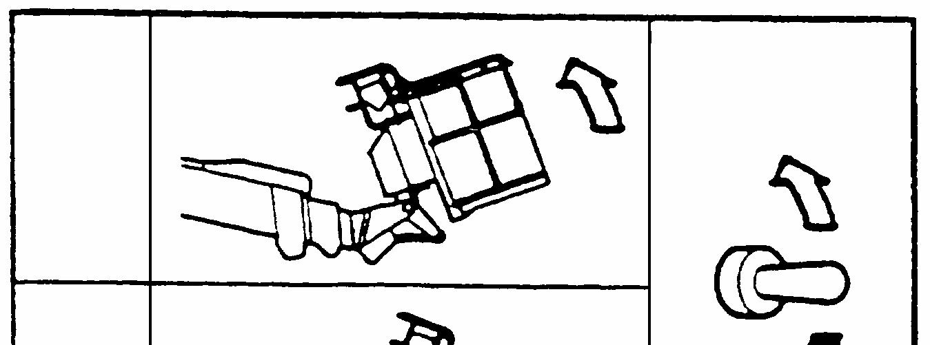
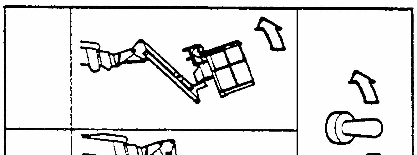
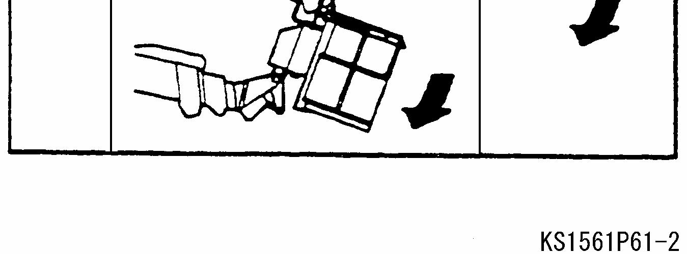
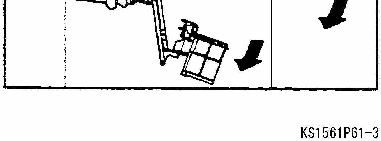
If the machine does not work due to engine or main pump failure, use the emergency pump to lower the platform. To operate the boom and the fly jib using the emergency pump, operate each boom function or fly jib switch with the emergency pump switch held in its ON position. Advice: It is not necessary to hold the dead-man switch in its ON position when operating the boom and the fly jib using the emergency pump.
Emergency pump switch
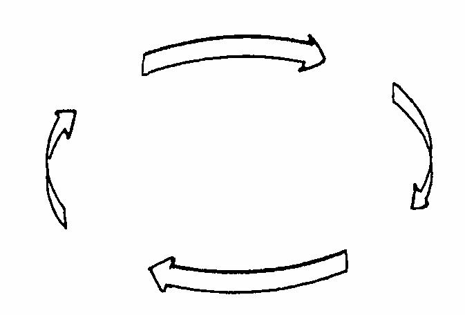
30 seconds Operate Rest 30 seconds
Emergency pump operation cycle diagram
Caution:
Rest 30 seconds Operate 30 seconds
l Operate the emergency pump every other 30 seconds. Continuous operation in excess of 30 seconds may damage the emergency pump. l Do not impose heavy load to the emergency pump, e.g. by attempting travel operation.
Advice:
l In the event that the emergency stop switch has been pressed at the upper control with no operator on the platform and it is necessary to lower the platform, you can lower the platform using the emergency pump from the lower control. l The engine automatically stops as you operate the emergency pump from the lower control while the engine key switch is in its UPPER control position.
3.4 Platform level adjustment
Danger: Do not allow any person or object on the platform when adjusting the platform level from the lower control.
Dead-man switch Platform level adjust switch
Hold the dead-man switch in its ON position and operate the platform level adjust switch to adjust the platform level.
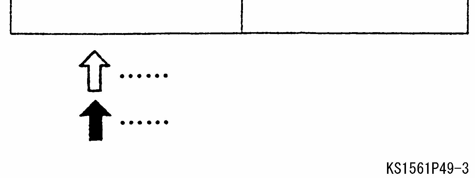
UP
UP
UP
UP
DO WN
DOWN
SR12B/ISR40B
DO WN
DOWN
SR12BJ/ISR40BJ
3.5 Indicator lights
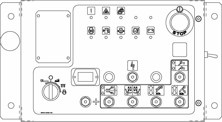
The following indicator lights are equipped on the lower control panel
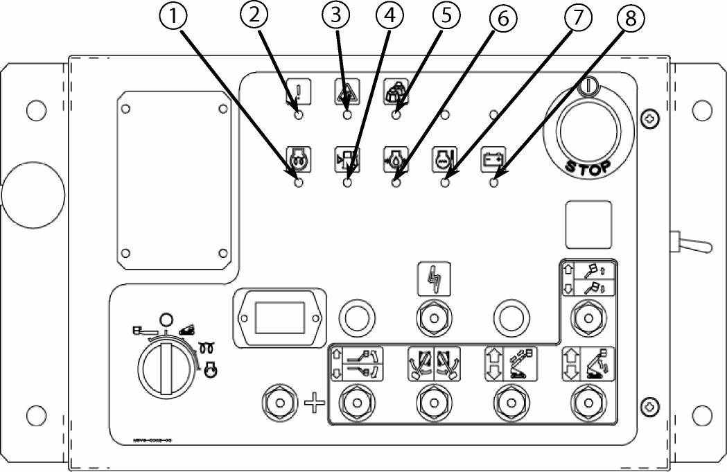
1 Pre-heat light 5 Overload warning light 2 System failure light 6 Oil pressure light 3 Tilt warning light 7 Overheat warning light 4 Fuel level light 8 Charge light
(1) Pre-heat light
This light goes on when the engine key switch is turned to its PRE-HEAT position. Pre-heat the engine for about 5 seconds when you start the engine in cold weather.
(2) System failure light
This light blinks, in the event of a computer control system failure. Stop using the machine and contact Aichi service shop for inspections, if this light blinks.
(3) Tilt warning light
This light goes on and the tilt alarm buzzer sounds when the machine tilts more than 5 degrees.
Do not elevate the platform when this light goes on.
(4) Fuel level light
This light goes on when the fuel level is low. Refill the fuel tank with diesel fuel when this light goes on. This light goes on when the remaining fuel reaches 23 liters (6 gallons).
(5) Overload warning light
This light blinks, the alarm buzzer sounds and all of the functions are disabled when the platform is overloaded.
(6) Oil pressure light
After starting the engine, this light goes off. The engine stops and this light goes on in the event that the engine oil pressure lowers abnormally. Check the engine lubrication system, e.g. shortage of engine oil, if this light goes on.
(7) Overheat warning light
In the event that the engine cooling water temperature rises abnormally, the engine stops and this light goes on to protect the engine from overheat. Check the engine cooling system, e.g. coolant level and fan belt, if this light goes on.
(8) Charge light
After starting the engine this light goes off, check the charging system, e.g. alternator and fan belt, if this light goes on while the engine is in motion.
3.6 Limit cancel switch
In the event that the “System failure light” blinks and the machine does not work due to computer control system failure, hold this limit cancel switch in its ON position and lower the platform, and then stop using the machine. The alarm buzzer sounds when the limit cancel switch is operated.
Caution:
l Do not use this switch except when emergency.
System failure light
Limit cancel switch
Advice:
l This limit cancel switch also cancels the functions of the overload sensing system. In the event that the overload sensing system disables all of the functions and it is necessary to lower the platform, hold this limit cancel switch in its ON position, retract the boom fully, and then lower the platform.
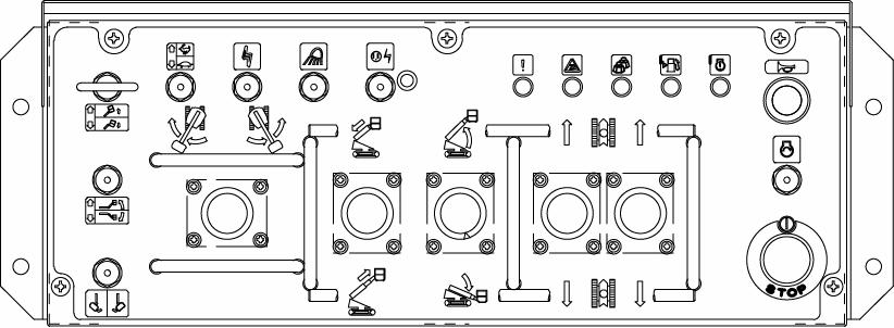
4. Upper control (Operation from Platform)
Be sure to set the engine key switch in its UPPER control position to operate the machine from the platform
Danger:
l Always wear an authorized safety harness and hook its lanyard to the specified anchor while you are on the platform. l Always stand on the platform floor firmly and maintain a safe posture while you are on the platform. l Do not reach out of the platform.
Caution:
l Prior to operate the machine on the platform, check that the platform is level and adjust the platform level, if necessary. l When using the machine for paintwork, first move the platform to the working position, and then be sure to close the cover of the upper control to protect the decals, joystick controllers, control switches and indicator lights. l Wipe off oil and water spilt on the platform floor so that personnel do not slip and fall on the platform. l Check the surroundings and make sure that no person or obstacle is around you or around the machine before operating the machine. l Especially be careful before rotating the boom. Check that no person or obstacle is around the turntable.
l Do not leave anything around the joystick controllers and the switches, which may be caught in, causing unintended movements.
UPPER control
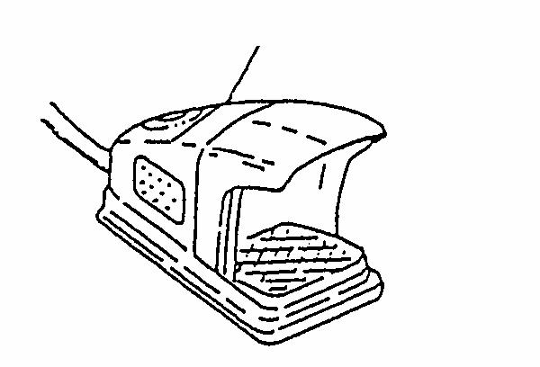
4.1 Foot switch
Depress the foot switch to operate the machine on the platform. However, the following functions are available without depressing the foot switch. l Engine start operation Foot switch
l Emergency stop operation l Horn operation
l Work light operation (Option)
Caution: Do not disable the foot switch in any way e.g. by binding.
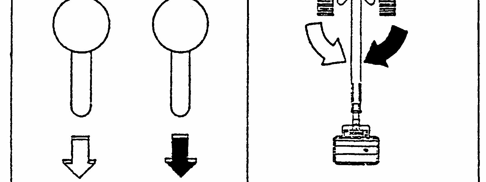
4.2 Travel operation
Use the travel joystick controllers and the travel speed select switch to perform the travel operations.
Caution:
When the turntable is rotated 180 degrees, the traveling direction becomes the opposite of the joystick controllers operating directions. Before traveling, always check the arrows located on the chassis to make sure the traveling direction.
Travel speed select switch
Travel joystick controllers
Arrows
Forward Reverse
Caution:
l Before traveling, make sure that no persons or obstacles are in the traveling direction.
l When traveling on rough terrain or on slope, retract the boom fully and set the boom under the horizontal.
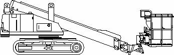
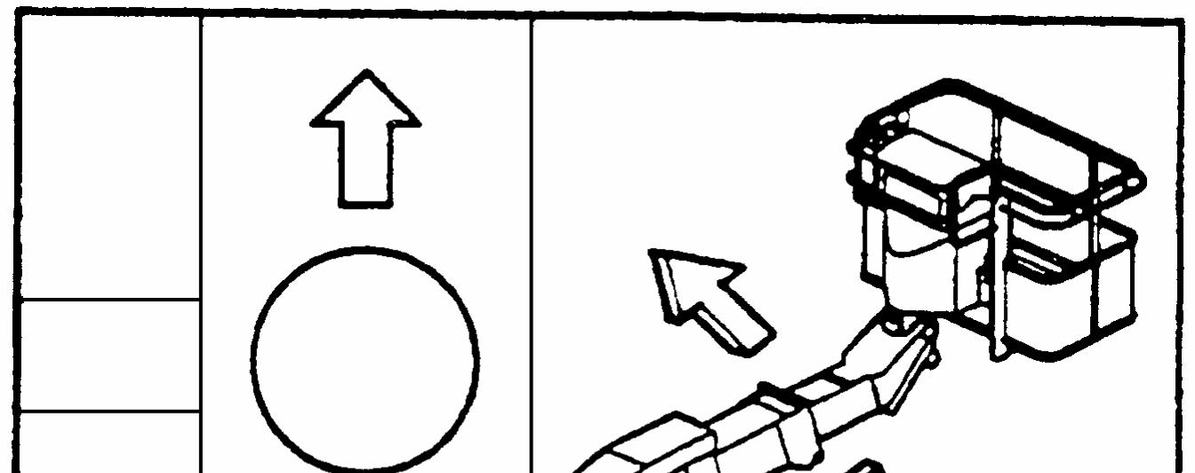
Danger:
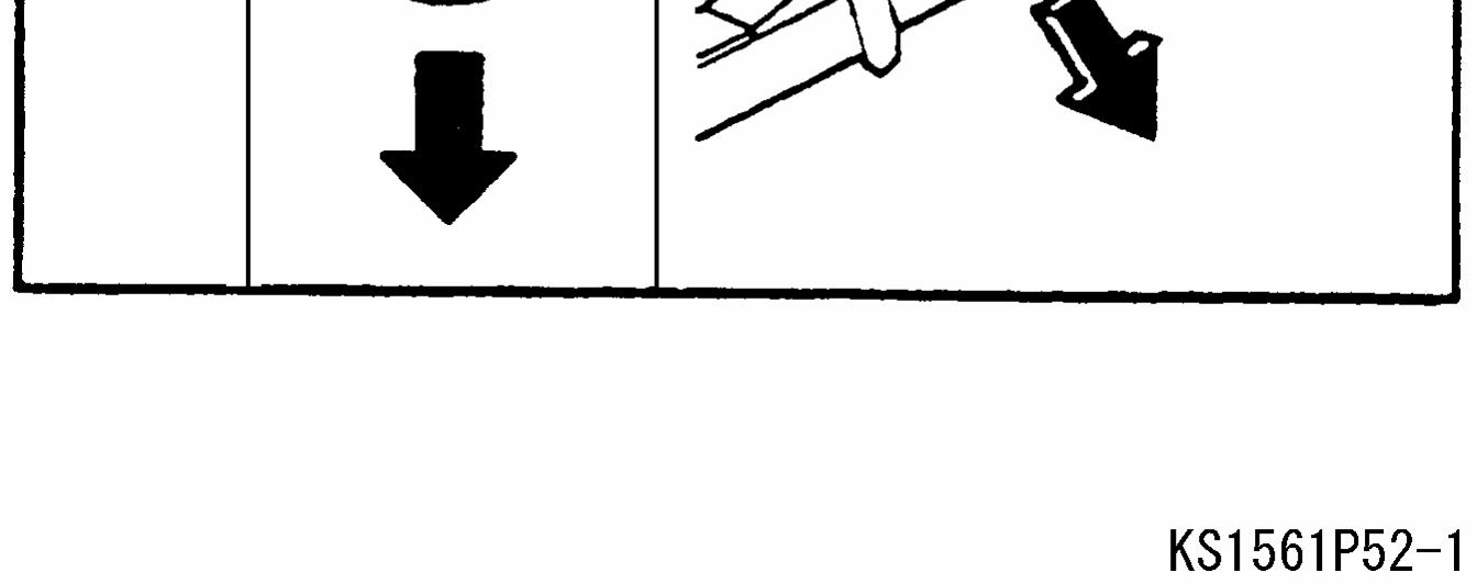
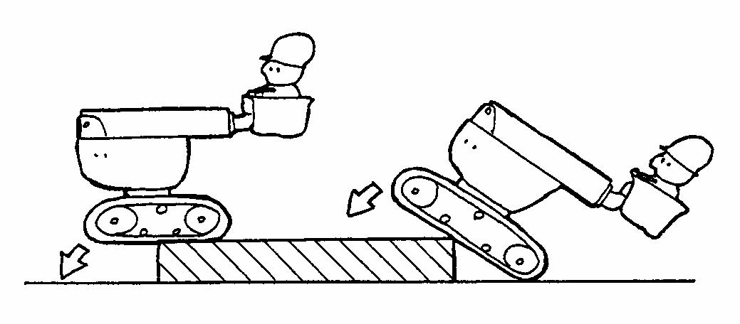
When traveling over a curb, retract the boom fully and set it under the horizontal, then travel the machine very slowly and carefully. The machine suddenly inclines and the platform jumps up or down roughly just after the gravity center of the machine pass the curb as shown in the figure below.
Check the overhead obstacles as well as the clearance between the platform and the ground, and then travel very slowly and carefully. If not, it may results in serious injury or death. For further detail, see the chapter “VI For Safety ” , section “2. During operation” of this manual.
Traveling direction
4.2.1 Travel speed select switch
The high and low traveling speeds are available. Set the travel speed select switch to select the high or low travel speed.
Danger:
l Do not set the travel speed select switch to its High-speed position and travel in the high speed when traveling over a curb.
Advice:
l The travel speed and travel functions are automatically limited by the functions of the travel speed limit and travel function limit systems. See “Chapter VIII” , “Sections 2 and 3” for the detail of the systems.
Travel speed select switch
Travel joystick controllers
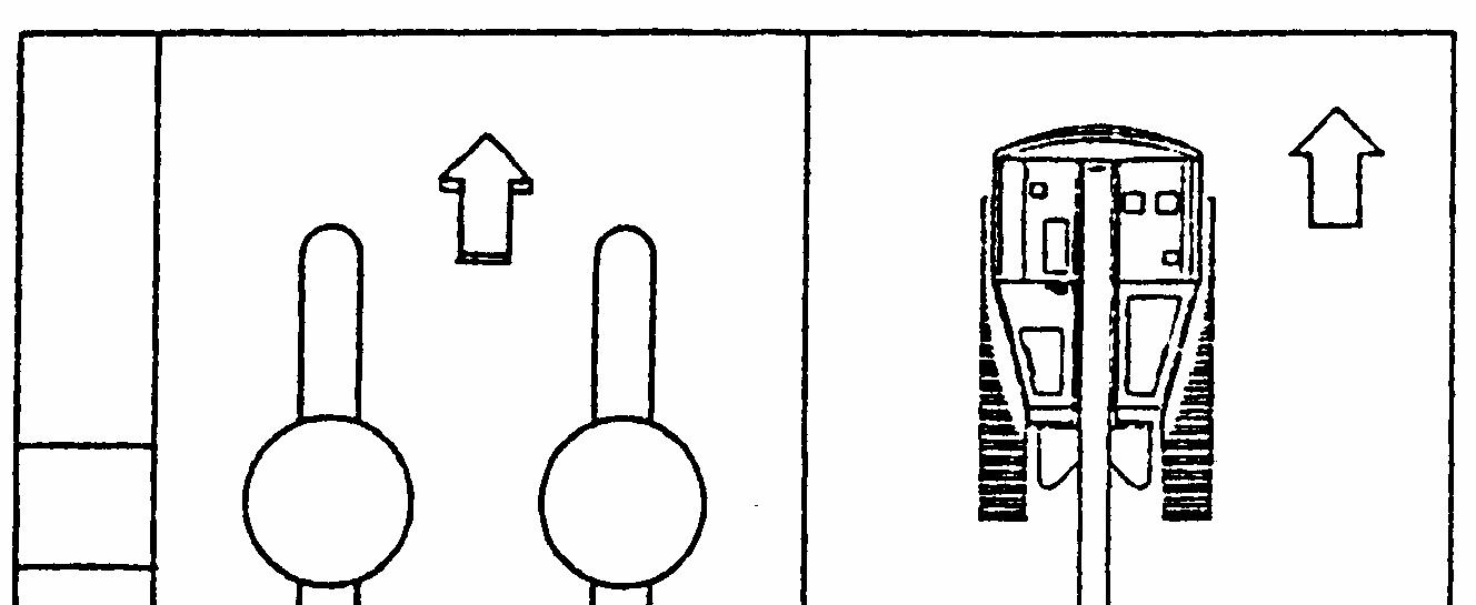
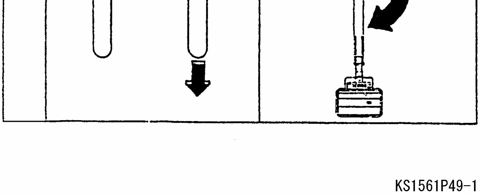
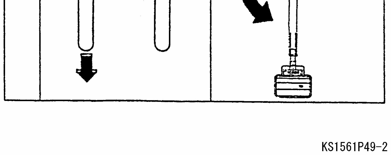
4.2.2 Straight forward and reverse
Depress the foot switch and operate both the travel joystick controllers to the traveling direction.
rd F or w a
e r se v R e
Caution: Before traveling, always check the arrows located on the chassis to make sure the traveling direction.
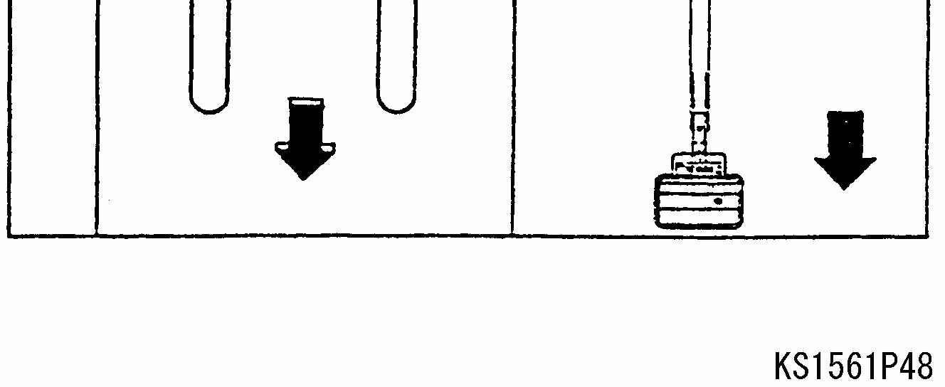
4.2.3 Pivot turn
Depress the foot switch and operate one of the travel joystick controllers as shown in the figures below. (a) Forward / Reverse turn to the left
rd F or w a
v e r se R e
(b) Forward / Reverse turn to the right
rd F orw a
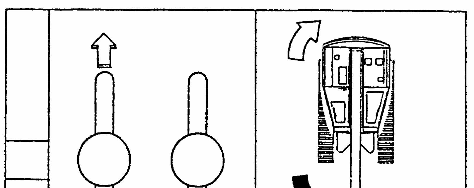
v e r se e R
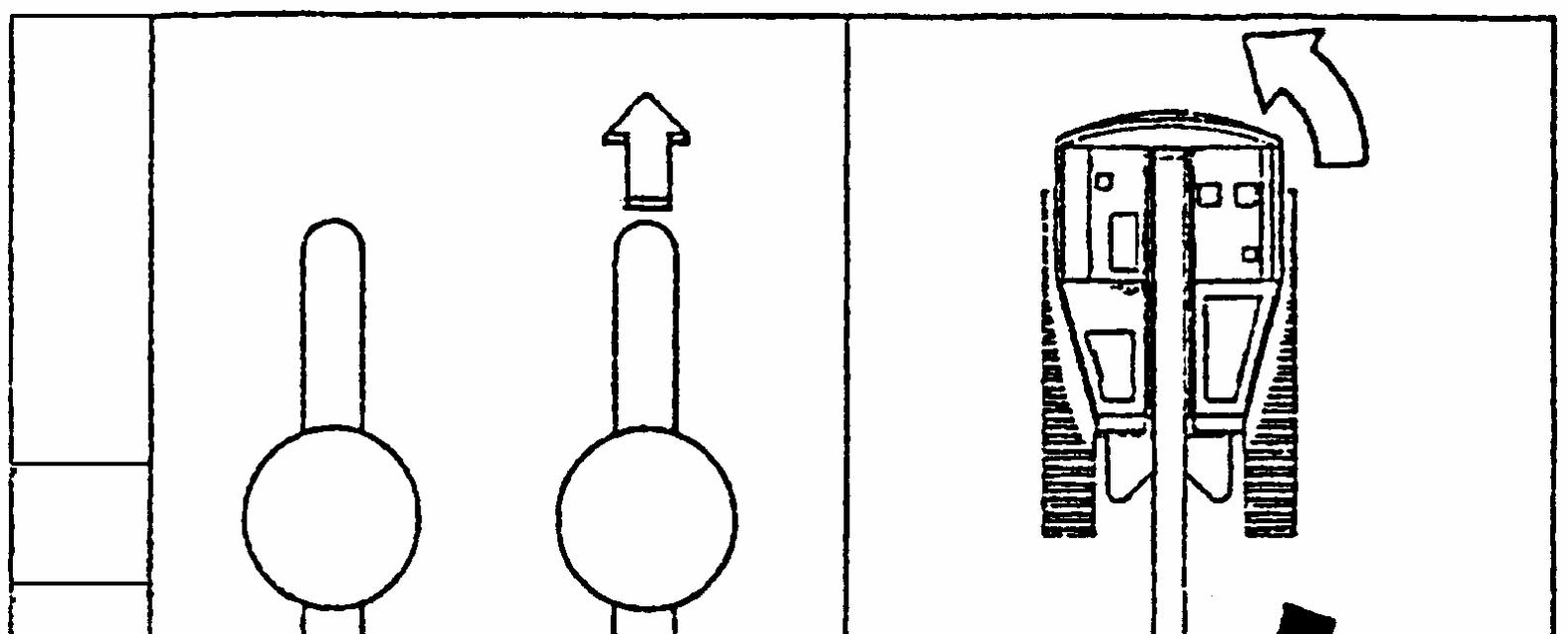
4.2.4 Spin turn
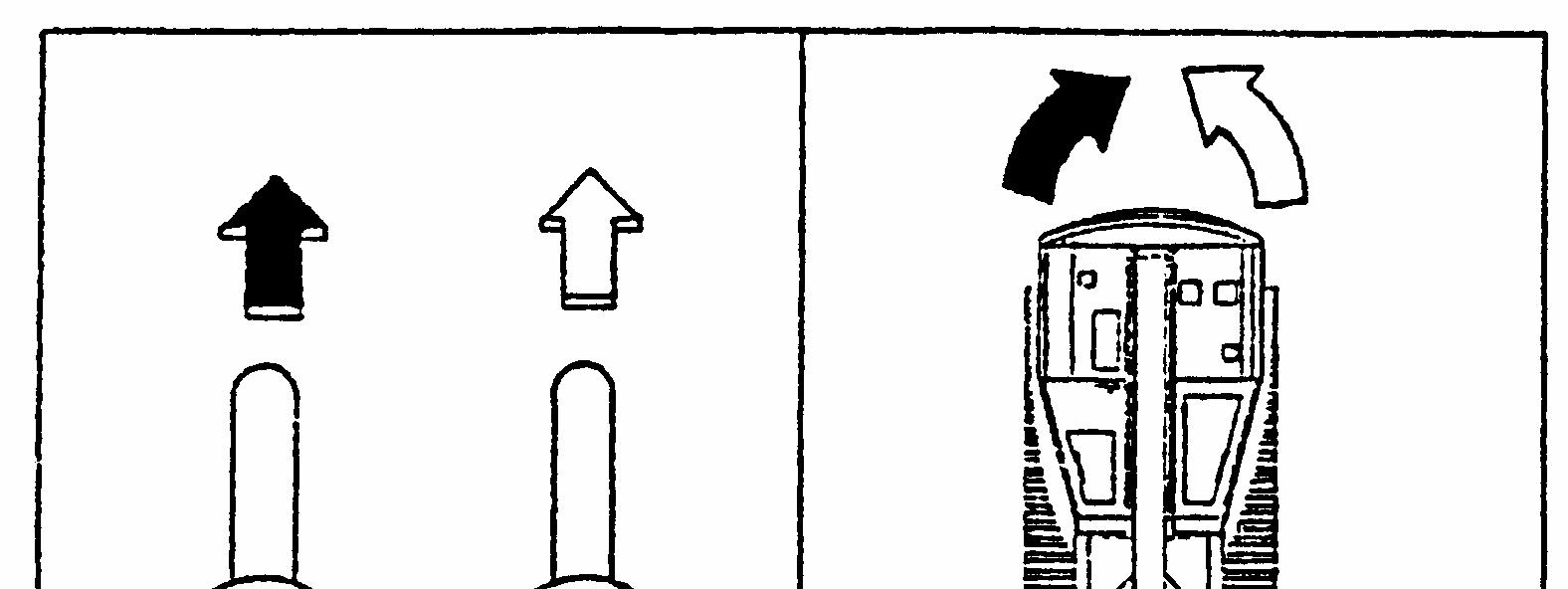
Depress the foot switch and operate the travel joystick controllers as shown in the figure below to make the CW or CCW spin turn.
Spin turn CCW Spin turn CW
4.3 Boom raising and lowering operation
Depress the foot switch and operate the boom elevation joystick controller to raise or lower the boom
se ai R
o w er L
Caution: Do not press the boom or the platform against the ground by lowering the boom.