1 minute read
Disassembling the External Modules


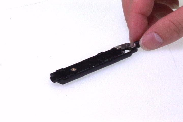
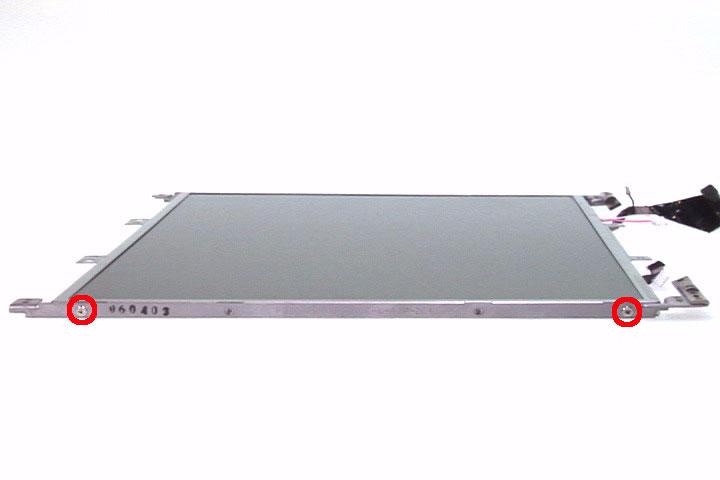
21. Take out the CCD hinge from the CCD cover as well. 22. Disconnect the CCD cable from the CCD board. 23. Remove the two screws fastening the left LCD bracket to the LCD.
24. Remove the left LCD bracket. 25. Remove the two screws holding the right LCD bracket.
26. Remove the right LCD bracket. 27. Tear off the mylar fastening the LCD cable and disconnect the LCD cable from the LCD.


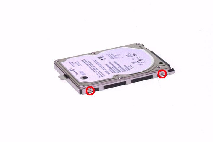
HDD Module
1. Remove two screws holding the HDD bracket to the HDD. 2. Remove another two screws fastening HDD bracket to HDD on the other side. 3. Carefully detach the HDD from the bracke.t


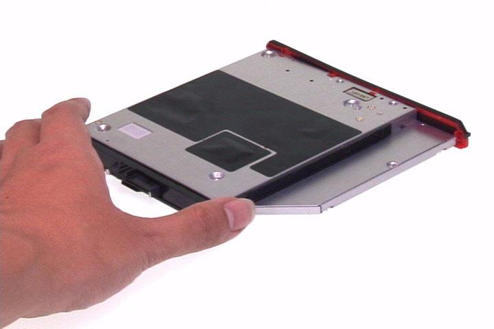
ODD Module
1. Remove the four screws fastening the ODD bracket to the ODD. 2. Remove the ODD bracket form the ODD. 3. Detach the ODD board from the ODD.


Troubleshooting
Please use the following procedures as a guide for computer problems. NOTE: The diagnostic tests are intended to test only Acer products. Non-Acer products, prototype cards, or modified options may occur errors or invalid responses. 1. Obtain the detailed fail symptoms as many as possible. 2. Verify the symptoms by attempting to recreate, running the diagnostic tests or repeating the same operation.