5 minute read
Disassembling the Main Unit


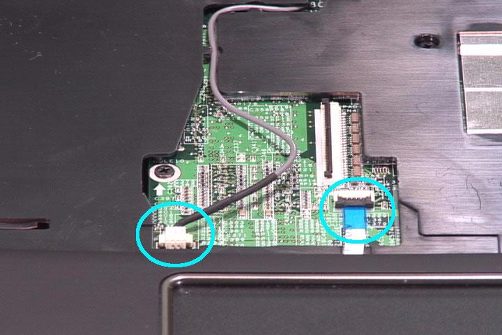
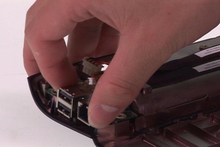
11. Disconnect the microphone cable and the touchpad board cable from the main board. 12. Disconnect the LCD cable from the main board. 13. Take out the microphone cable from the upper case.
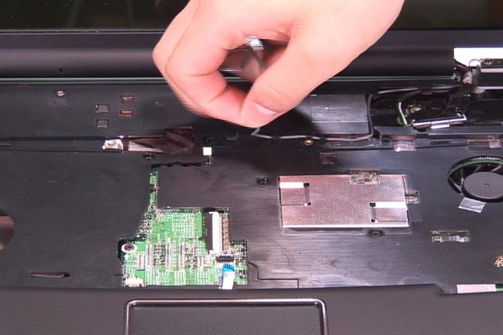
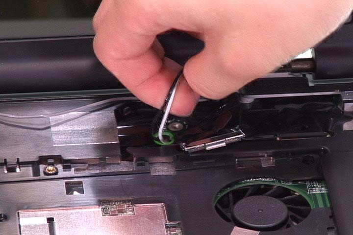
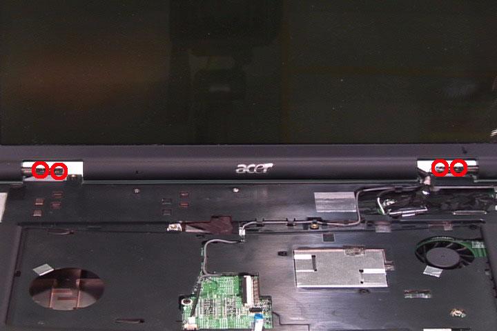
14. Pull out the wireless antenna set from the back side. 15. Remove the four screws holding the LCD module. 16. Detach the LCD module from the laptop.


Separating the Upper Case and the Lower Case
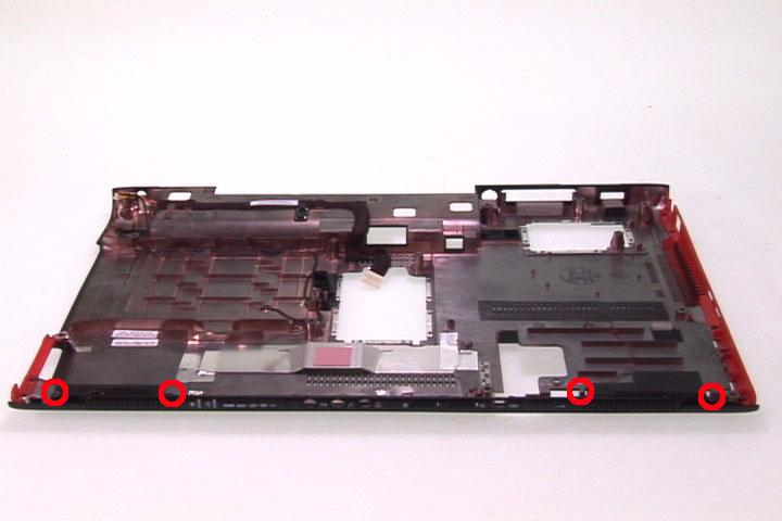
1. Remove the nine screws holding the upper case and the lower case assembly on the front side. 2. Remove the 16 screws fastening the upper case and the lower case assembly on the bottom side.
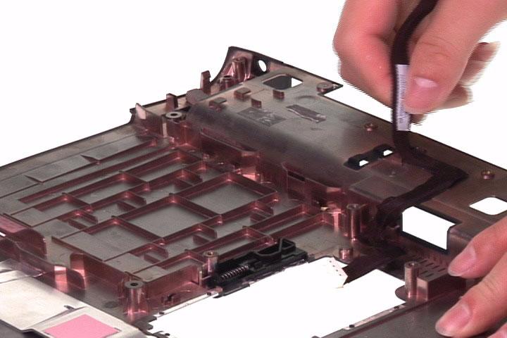
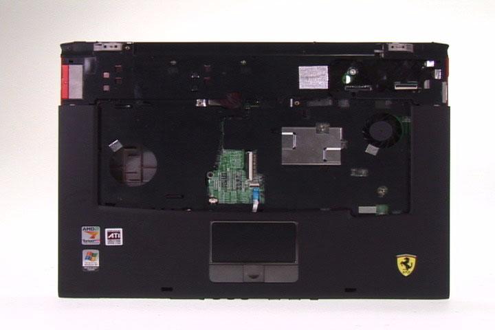
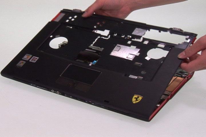
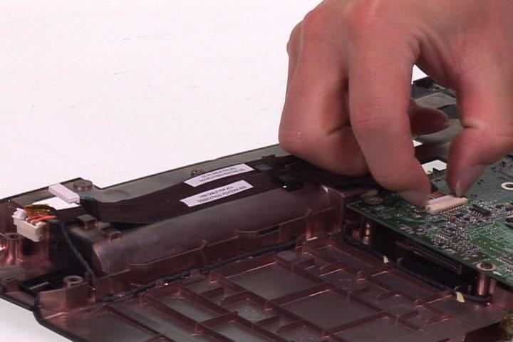
3. Turn over the main unit and disconnect the bluetooth cable from the main board. 4. Disconnect the power board cable from the main board on the bottom side. 5. Carefully detach the upper case assembly from the lower case assembly.


Disassembling the Upper Case Assembly
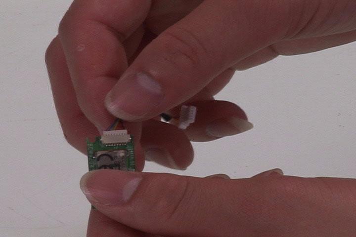
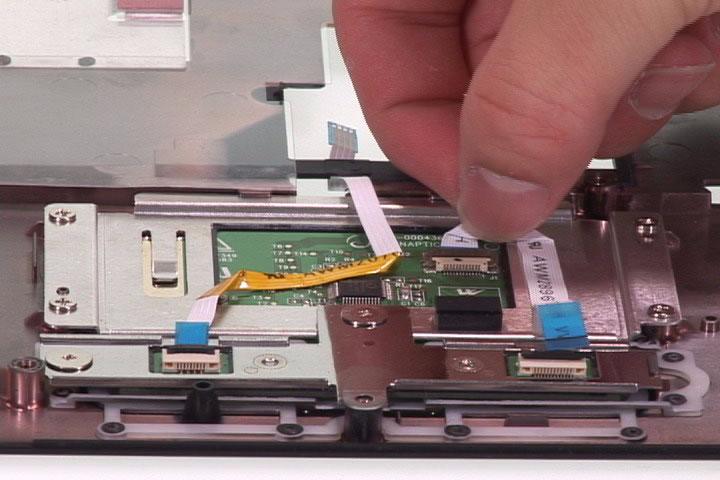
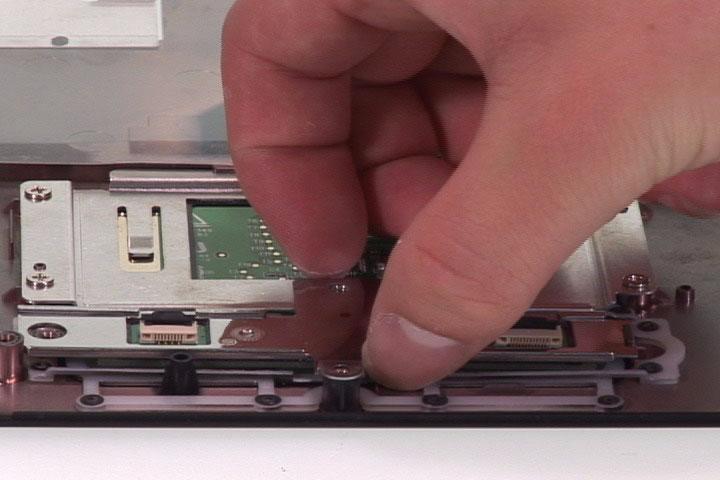
1. Detach the bluetooth module from the upper case. 2. Disconnect the bluetooth cable from the bluetooth board. 3. Tear off the mylar fastening the touchpad to touchpad board cable.
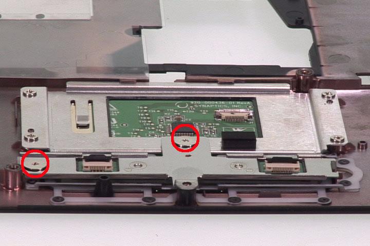
4. Disconnect the touchpad to touchpad board cable and remove it. 5. Disconnect the touchpad cable and detach it from the touchpad. 6. Remove the two screws holding the touchpad bracket.
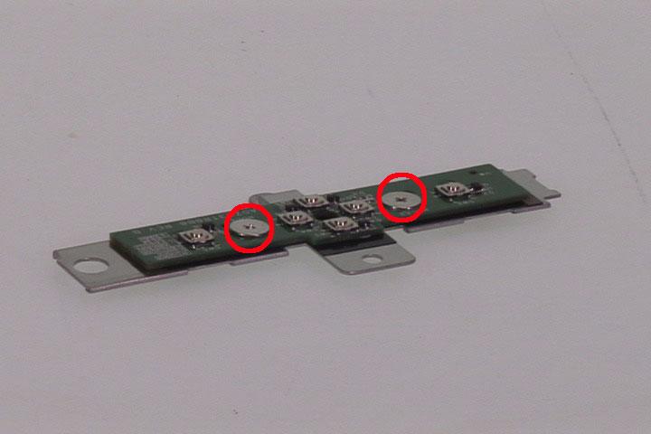
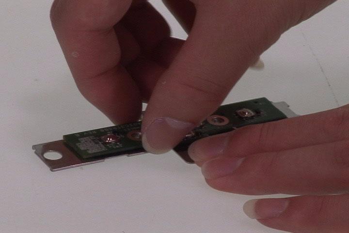
7. Detach the touchpad board bracket (with touchpad board) from the upper case. 8. Remove the two screws fastening the touchpad board to the touchpad board bracket. 9. Detach the touchpad board from the bracket.
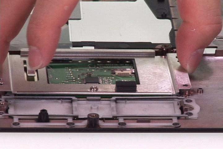
10. Remove the four screws fastening the touchpad bracket. 11. Detach the touchpad bracket from the upper case. 12. Then remove the touchpad.


Disassembling the Lower Case Assembly
1. Disconnect the (1) DC-in cable, (2) modem cable and the (3) USB cable. 2. Take the power board out of the lower case. 3. Disconnect the USB cable from the main board and detach the cable from the lower case.
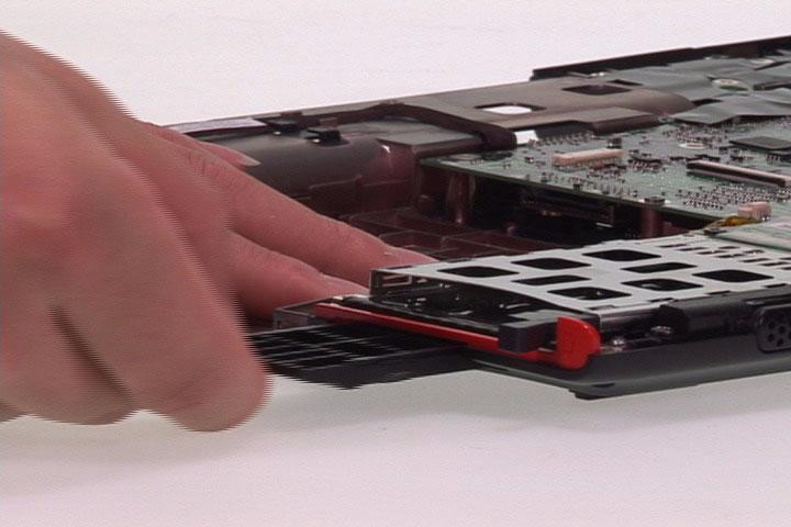
4. Press the dummy PC card button and remove the dummy PC card. 5. Detach the dummy expand card from the lower case.
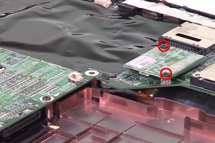
6. Tear off the mylar fastening the modem cable. 7. Disconnect the modem cable from the modem board. 8. Remove the two screws holding the modem board.
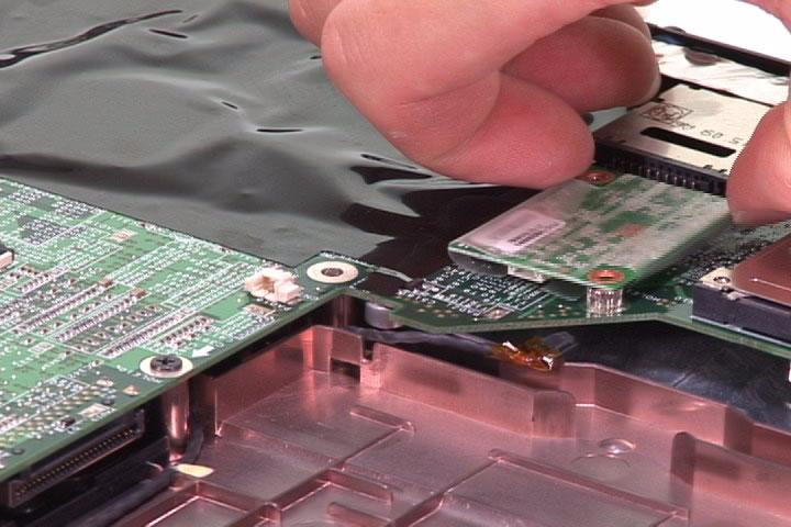
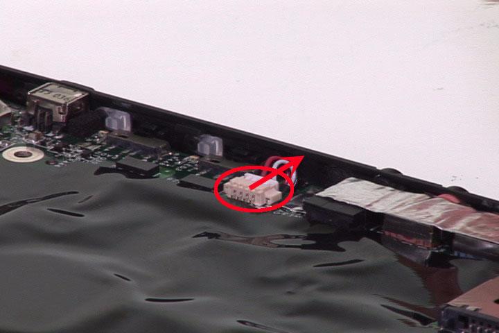
9. Disconnect the modem board from the main board. 10. Disconnect the speaker set cable from the main board. 11. Remove the two screws fastening the main board assembly to the lower case.


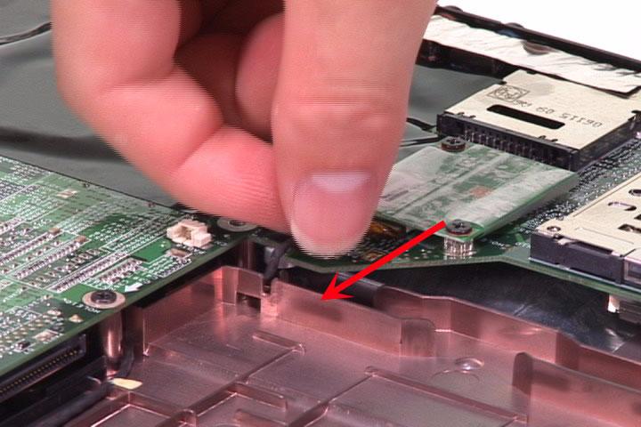
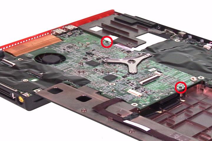
12. Cautiously take out the main board assembly from the lower case. 13. Remove the four screws holding the speaker set to the lower case. 14. Detach the foil fastening the speaker cable to the lower case.
15. Then detach the speaker set from the lower case. 16. Then take out the modem cable from the lower case as well. 17. Detach the DC-in cable from the lower case.
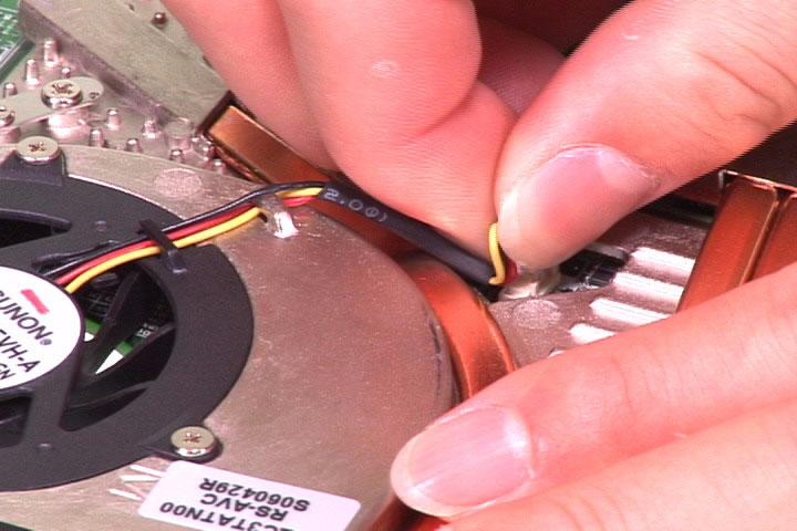
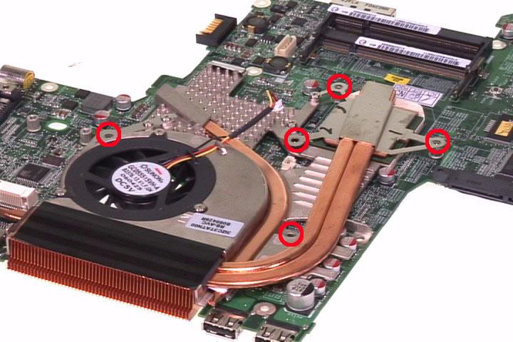
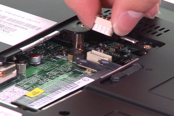
18. Disconnect the RTC battery then detach it from the main board. 19. Disconnect the thermal module cable connector from the main board. 20. Remove the five screws fastening the thermal module to the main board.
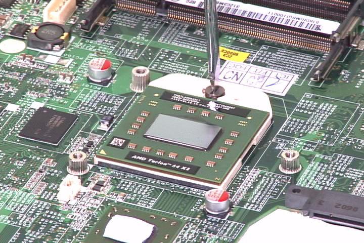
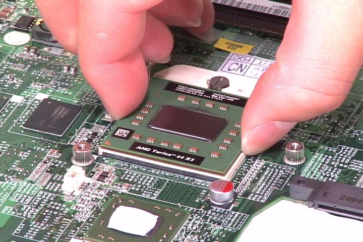
21. Remove the thermal module from the main board. 22. Use a flat-headed screwdriver to release the CPU lock. Please turn clock-wise. 23. Then carefully take out the CPU from the CPU socket on the main board.