TROUBLESHOOTING
Electrical Systems All tests of the electrical components should be made using the digital Fluke Model 77 Multimeter. Replace any component that does not have a test value within specifications. NOTE: Whenever using a digital-style tester, “open (infinite resistance)” denotes an overload and the meter reading will be OL since the meter is not calibrated to register resistance values of that magnitude. NOTE: Always check the appropriate fuse before testing a component for failure. NOTE: Whenever a part is worn excessively, cracked, or damaged in any way, replacement is necessary.
1. Remove the spark plugs and visually check their condition. Replace any fouled plug. Attach the spark plugs to the high tension leads and ground them to the engine.
CAUTION Do not ground the spark plug on the cylinder head cover. The cover is made of magnesium and any contact with spark or electrical arc will severely pit the surface.
CAUTION Before checking for spark, place all the engine switches in the deactivated position. In the event the engine could be flooded, engage the starter several times to clear the engine of excess fuel.
CAUTION
SPECIAL TOOLS
Never crank the engine over without grounding the spark plugs. Damage to coils and/or CDI/ECM may result.
A number of special tools must be available to the technician when servicing the electrical systems.
NOTE: Make sure the ignition switch and the emergency stop switch are in the ON position.
NOTE: When indicated for use, each special tool will be identified by its specific name, as shown in the chart below, and capitalized.
2. Crank the engine over and check for spark. If no spark is present, check to make sure the throttle cable is properly tensioned. Compress the throttle control and while holding the throttle control in this position, crank the engine over and check for spark. If spark is now present, adjust the throttle cable tension.
Description CATT II
p/n 0544-023
Arctic Cat Diagnostic System Manual
2256-974
Laptop Diagnostic Tool
0744-048
Actuator Test Harness
0644-518
Fluke Model 77 Multimeter
0644-559
MaxiClips
0744-041
Throttle Position Sensor (TPS) Adjustment Tool Kit
3639-891
NOTE: Special tools are available from the Arctic Cat Service Parts Department.
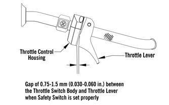
Ignition System NOTE: There must be 0.030-0.060 in. free-play between the throttle lever and the control housing.
TESTING Throttle Control Switch
1. Disconnect the handlebar harness connector; then connect the red meter lead to the yellow wire; then connect the black meter lead to the black wire. 2. With the throttle lever in the idle position, the meter must read less than 1 ohm. If the meter reads OL (infinite resistance), replace the control assembly. 3. Move the throttle lever to the wide open position. The meter must read OL (infinite resistance). If the meter reads less than 1000 ohms, replace the control assembly.
Throttle Position Sensor VERIFYING TPS ADJUSTMENT TOOL
0752-478
Before using the TPS adjustment tool, verify its battery condition. The battery used in the tool is a 9-volt battery. To check battery condition, use a digital volt/ohmmeter set on DC volt scale. Test between the adjustment tool black and red jacks. Insert the red lead of the digital voltmeter into the red jack of the adjustment tool and the black lead of the digital voltmeter into the black jack of the adjustment tool. The green power light of the analyzer should now be illuminated. If voltage is found below 4.9 volts, replace the battery. NOTE: The Test Harness must be plugged into the analyzer for testing voltage. Always verify battery voltage is at least 4.9 DC volts before testing TPS.
70