FUEL SYSTEM
Fuel Systems
The fuel is first drawn into the electric fuel pump through multiple pick-up valves and hoses. The fuel is then routed through a high-pressure fuel hose to the fuel rail.
This section has been organized for servicing the fuel systems; however, some components may vary from model to model. The technician should use discretion and sound judgment when removing/disassembling and assembling/installing components.
The fuel pressure is maintained in the fuel rail by the fuel regulator. With the fuel pressure maintained at a constant psi, the ECM evaluates the information it receives from the electrical sensors and opens the injectors for precise periods of time (pulse widths) to meet engine demands.
Whenever any maintenance or inspection is made on the fuel system where fuel leakage may occur, there should be no welding, smoking, or open flames in the area.
Individual Components
WARNING
ECM
Since the fuel supply hose may be under pressure, remove it slowly to release the pressure. Place an absorbent towel around the connection to absorb gasoline; then remove the hose slowly to release the pressure. Always wear safety glasses when removing the fuel hoses.
NOTE: Whenever a part is worn excessively, cracked, or damaged in any way, replacement is necessary. SPECIAL TOOLS
A number of special tools must be available to the technician when servicing the fuel systems. NOTE: When indicated for use, each special tool will be identified by its specific name, as shown in the chart below, and capitalized. Description EFI Analyzer
p/n 0744-049
The ECM is the brain of the EFI system. It uses sensor inputs to determine the correct fuel/air ratio for the engine given the existing conditions of altitude and temperature. If any of the sensors should fail while the engine is running, the ECM will sense a problem and go into a “fail safe” mode. This is an over-rich condition and will greatly reduce performance. However, the engine will be protected from a possible lean condition and engine damage. The ECM is equipped with a self-diagnostic system utilizing the service icon in the speedometer/tachometer and remains illuminated when a problem exists with any of the sensors. The technician can determine the problem sensor by reading the code shown on the readout screen and applying it to the ECM Diagnostic Codes chart (see Self-Diagnostic System/Codes in this section). Removing
EFI Diagnostic System Manual
2257-850
1. Remove both access panels; then remove the hood.
EFI Diagnostic System Manual (Instructions)
2259-020
Fluke Model 77 Multimeter
0644-559
Fuel Hose Clamp Tool
0644-545
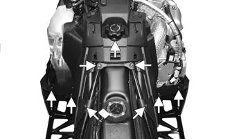
2. Remove the air intake assembly from the throttle body and the radiator.
Fuel Pressure Test Kit
0644-493
Vacuum Test Pump
0644-131
Fuel Pump Installation Tool Kit
0744-074
Laptop Diagnostic Test Kit
0744-050
Laptop Diagnostic Tool
0744-060
Oil Injection Usage Tool
0644-007
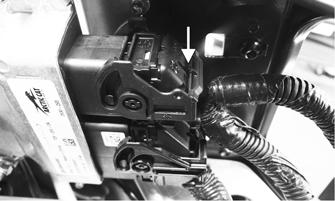
3. Press the retaining tabs on the ECM connectors in; then rotate the connector arms up while will allow the connectors to be released from the ECM.
NOTE: Special tools are available from the Arctic Cat Service Parts Department.
Fuel System INTRODUCTION
The Arctic Cat EFI System operates off a series of coils located on the stator and is made up of the following components. An engine control module (ECM) calculates input from sensors (air temperature sensor, coolant temperature sensor, throttle position sensor, and a knock sensor) to provide the engine with the correct fuel mixture and timing for optimum operation. 64
YM-052
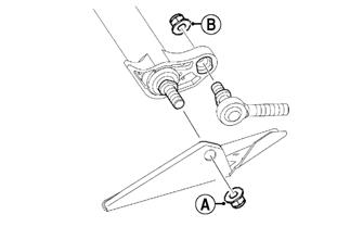
4. Remove the four cap screws and nuts securing the ECM to the chassis.