40 minute read
Engine

NOTE: Whenever a part is worn excessively,
cracked, or damaged in any way, replacement is necessary.
Engine Removing/Installing
This engine servicing sub-section has been organized to show a progression for the removing/installing of the Arctic Cat 2000 engine. For consistency purposes, this sub-section shows a complete and thorough progression; however, for efficiency it may be preferable to remove only those components needing to be addressed. Also, some components may vary from model to model. The technician should use discretion and sound judgment. SPECIAL TOOLS A number of special tools must be available to the technician when performing service procedures in this engine section.
NOTE: When indicated for use, each special tool
will be identified by its specific name, as shown in the chart below, and capitalized.
NOTE: Special tools are available from the Arctic
Cat Service Parts Department.
Description p/n
Drive Clutch Bolt Tool 0644-281 Drive Clutch Puller 0744-062 Drive Clutch Spanner Wrench 0644-136 Driven Clutch Puller 0644-469
CAUTION
Never attempt to substitute any other drive clutch puller for the recommended puller or severe clutch or crankshaft damage will occur.
Removing
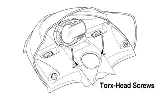
1.Remove the hood and the left-side and right-side access panels; then remove the Torx-head screws securing the console. 2.Lift the rear of the console and disconnect the console/main harness plug-in; then remove the console and disconnect the battery. 3.Remove the springs securing the expansion chamber to the exhaust manifold and resonator and remove the expansion chamber; then remove the cap screw, lock nut, and washer securing the resonator to the front upper frame and remove the resonator. 4.Remove the cap screws and lock nuts securing the heat shield to the chassis. Account for the U-nut clip. 5.Remove the cap screws securing the recoil starter.
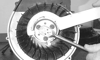
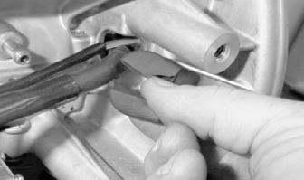
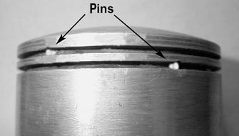
Note the position of the ground wire (for assembling purposes); then move the recoil starter up and out of the way. 6.Remove the two pins securing the belt guard and remove the drive belt; then using Drive Clutch Bolt
Tool, remove the cap screw and high-collar washer securing the drive clutch to the crankshaft. 7.Using Drive Clutch Puller and Spanner Wrench, tighten the puller. If the drive clutch will not release, sharply strike the head of the puller. Repeat this step until the clutch releases. Remove the drive clutch and the drive belt. If applicable, account for the two sleeves.
NOTE: Apply a film of grease to the end of the
puller to aid in removal of the drive clutch.
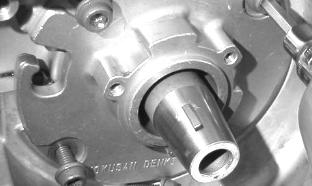
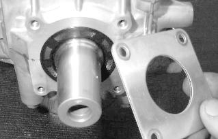
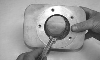
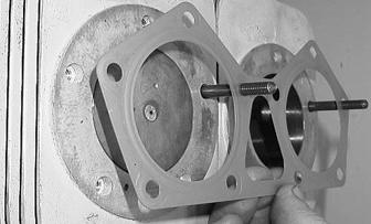
8.Remove the cap screw from the driven clutch and slide the driven clutch off the gear case input shaft.
Account for alignment washers (if applicable).

FZ021
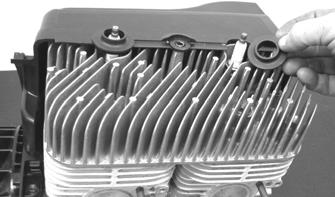
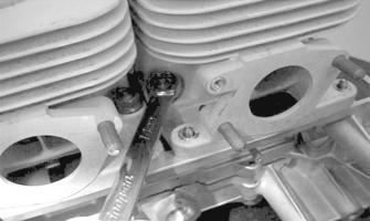
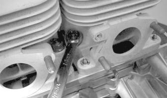
9.Remove the nuts and lock washers securing the exhaust manifold to the engine; then remove the manifold and account for the gaskets.

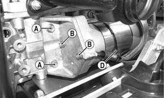
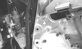
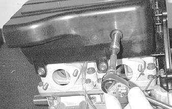
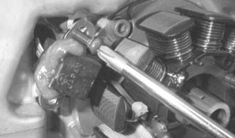
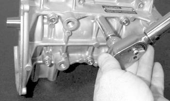
10.Remove the two cap screws (A) securing the
MAG-side bracket to the engine; then remove the two cap screws (B) securing the bracket to the starter motor assembly. Account for a star washer behind the negative battery cable.
XM217B
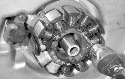
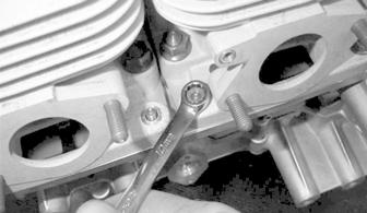
11.Remove the two lock nuts (C) securing the starter motor to the PTO-side bracket.

XM216B
NOTE: At this time, route the starter motor ground
wire out from the engine plate.
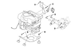
12.Remove the cap screw (A) securing the rear
MAG-side engine mounting bracket to the chassis; then remove the three remaining lock nuts (B) securing the engine plate to the chassis.
0743-921
13.Move the engine forward enough to remove the cap screws (C) securing the rear MAG-side engine mounting bracket to the engine; then remove the bracket.
14.Remove the lock nuts and cap screws (D) securing the snubber bracket to the chassis; then remove the bracket. 15.Remove the cap screws and lock nuts securing the headlight support bracket to the front upper frame; then remove the bracket and account for the mounting hardware. 16.Loosen the carburetor flange clamps and remove the carburetors from the intake flanges; then remove the clamp and disconnect the impulse line from the crankcase. CAUTION
Use care when moving the engine forward not to damage the wiring harness.

FZ006
CAUTION
After the carburetors have been removed, secure them in an upright position to avoid fuel running out of the vent tubes.
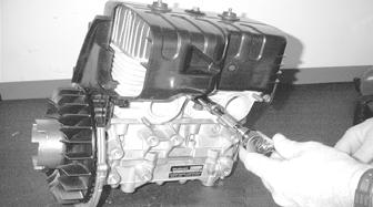
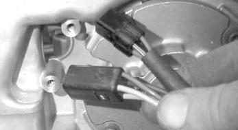
17. Disconnect the oil-injection cable from the oil pump and account for the E-clip and washer; then disconnect the oil supply hoses from the pump and plug the hoses to prevent leakage. 18.Remove the cap screw and lock nut securing the wiring harness clamp to the chassis; then remove the spark plug wires from the spark plugs. Disconnect the coil wire and CDI connectors and route and secure the harness to the engine to avoid damage when removing the engine from the chassis.
NOTE: For assembling purposes, note the routing
and securing locations of the wiring harness and the routing of the oil hoses and impulse line.
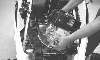
19.Turn the steering all the way to the right; then rotate the engine allowing enough room to lift it up and out of the front of the chassis.
FZ013
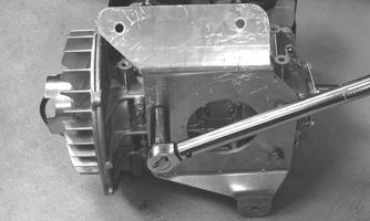
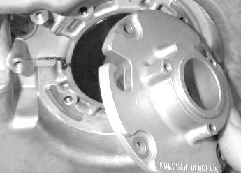
20.Remove the two cap screws securing the rear
PTO-side crankcase snubber bracket.

FZ022A
21.Remove the four cap screws securing the engine plate to the engine; then remove the plate.

FZ014
Installing
1.Install the engine plate to the engine with four cap screws. Tighten to 36 ft-lb.
FZ025
2.Install the PTO-side crankcase snubber bracket with two cap screws; then tighten to 20 ft-lb.
FZ022A
3.With the steering turned all the way to the right, install the engine into the chassis and position the engine forward of the mounting locations to access the oil pump and electrical connectors.
FZ013
4.Route the wiring harness as noted during disassembly and connect the plug-ins to the CDI and ignition coil; then connect the main harness plug-in. NOTE: Prior to connecting the harness, clean all
plug-ins with contact cleaner and apply Dielectric Grease to the connectors.
5.Connect the oil line to the oil-injection pump and secure with the clamp; then with the oil-injection pump cable properly routed, install the cable to the oil-injection pump and secure with the washer and
E-clip.
NOTE: Verify the mark on the control arm is
aligned with alignment mark on the oil-injection pump boss in the full-open position. If the marks are not aligned, adjust synchronization by loosening the jam nuts on the adjuster. Rotate the jam nuts/adjuster nut until proper alignment is attained. Tighten jam nuts.
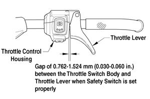
NOTE: When the cable/linkage adjusting nut is
adjusted correctly, the throttle lever will move approximately 1/8 in. before the oil-injection pump arm begins to move.
6.Remove the oil bleed plug from the oil-injection pump. When oil flows from pump free of air bubbles and the hose is full of oil, install the oil bleed plug and tighten. NOTE: Place a cloth beneath the oil-injection pump
to contain any oil spilled during the bleeding process.
7.With the throttle cable and fuel lines properly routed, install the flange clamps to the intake flanges; then install the carburetors and secure with the clamps.
FZ006
8.Install the headlight support bracket and secure the bracket with the cap screws and lock nuts. 9.Install the rear MAG-side engine mounting bracket to the engine with the three cap screws (C). Tighten to 20 ft-lb; then position the engine to the chassis mounts.
0743-921
10.Install the snubber bracket; then secure the bracket to the chassis with the cap screws and lock nuts (D).
Tighten to 20 ft-lb. 11.Install the three lock nuts (B) securing the engine plate to the chassis and tighten to 20 ft-lb; then install the cap screw (A) securing the rear MAG-side engine bracket to the chassis. Tighten to 20 ft-lb. 12.Carefully work the carburetor boots over the intake bore of the carburetor 13.Install the starter motor into the PTO-side bracket and loosely secure using existing lock nuts; then loosely secure the MAG-side bracket to the starter motor using the existing small cap screws and star washer (threads coated with blue Loctite #243).
Tighten to 20 ft-lb. 14.Loosely secure the MAG-side bracket to the engine using the existing large cap screws (threads coated with blue Loctite #243). Tighten the small cap screws (B) to 96 in.-lb, the two lock nuts (C) to 25 ft-lb and the large cap screws (A) to 25 ft-lb (in that order). Secure both battery cables to the starter motor using a cable tie (D).
XM216B
XM217B
15.Apply a thin coat of high-temperature silicone sealant to each exhaust port; then install the exhaust gaskets. 16.Apply a thin coat of high-temperature silicone sealant to the mating surfaces of the exhaust manifold; then install the exhaust manifold and secure with nuts and lock washers. Tighten the nuts to 15 ft-lb. 17.Place the recoil starter into position and secure the starter with the cap screws (threads coated with blue
Loctite #243). In a crisscross pattern, tighten to 60 in.-lb. 18.Install the ground wire to the proper location as noted during disassembly; then with the U-nut clip in place, install the heat shield and secure the shield with the cap screws and lock nuts.
19.Install the oil supply hose and low oil sensor wire to the oil reservoir and install the reservoir. Secure with the cap screws and lock nuts. 20. Secure the wiring harness to the chassis with the wiring harness clamp, cap screw, and lock nut. Tighten securely.
FZ012A
21.Install the grommets into the spark plug opening of the engine shroud; then connect the spark plug wires and install the negative cable to the battery. 22.Apply a few drops of oil to the cap screw threads; then place the drive clutch into position on the crankshaft and secure with the cap screw and lock washer.
Tighten to 51 ft-lb. NOTE: Before installing the drive clutch, be sure to
wipe both the crankshaft and clutch mounting taper clean using a clean towel.
CAUTION
When installing the drive clutch, do not tighten the clutch cap screw with any kind of impact tool. Tighten cap screw using a hand torque wrench only. Failure to do so could result in stationary sheave damage.

FZ018
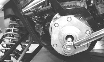
23.Install the alignment washers (if applicable); then install the driven clutch on the gear case input shaft.
Tighten the cap screw to 32 ft-lb.
FZ021
CAUTION
Do not allow the driven clutch to “float” on the input shaft. Damage to the driven clutch will occur.

FZ019
CAUTION
Do not apply Loctite to the cap screw or damage to the gear case will occur.
24.Check drive clutch/driven clutch alignment (see
Drivetrain/Track/Brake Systems section). Install the drive belt. Check belt deflection. Secure the belt guard. NOTE: Make sure the rubber exhaust bumper is in
position on the close-off cover before installing the expansion chamber.
FZ017B
25.Install the exhaust resonator and secure to the upper frame with the washer, cap screw, and lock nut. 26.Place gaskets on the resonator and exhaust manifold; then install the expansion chamber. Secure the chamber to manifold and resonator with the springs.
NOTE: When installing the exhaust manifold
springs, the long hook portion of the spring must be attached to the exhaust manifold or premature spring failure will result.
27.Place the console into position on the headlight support bracket (do not secure the console with the
Torx-head screws at this time); then connect the console/main harness plug-in. 28.Install and close the left-side and right-side access panels and the hood; then start the engine and warm up to operating temperature. Verify that all components are functioning properly and that coolant is circulating through the cooling system properly. 29.Verify the tightening torque of the drive clutch. 30.Secure the console to the steering support with the
Torx-head screws and tighten the screws securely; then close the left-side and right-side access panels and close the hood.
CAUTION
Never run the engine with the hood harness disconnected or damage to the electrical system will result. After running the engine to the proper operating temperature, shut the engine off; then open the hood and access panels and inspect for any signs of coolant, gasoline, or oil leakage.
CAUTION
If the engine had a major overhaul or if any major component was replaced, proper engine break-in procedures must be followed (see General Information/Foreword section). If the proper engine break-in procedures are not followed, severe engine damage may result.
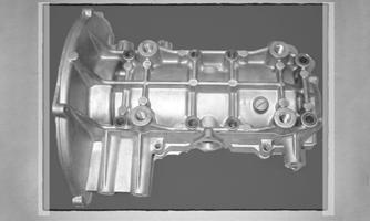
Assembly Schematic
Torque Specification Tolerances Torque (ft-lb) Tolerance
0-15 ±20% 16-39 ±15% 40+ ±10%

570-ENG12

570ENG12
Engine Servicing
This engine sub-section has been organized to show a progression for servicing of the Arctic Cat 2000 engine. For consistency purposes, this sub-section shows a complete and thorough progression; however, for efficiency it may be preferable to disassemble only those components needing to be addressed. Also, some components may vary from model to model. The technician should use discretion and sound judgment. SPECIAL TOOLS A number of special tools must be available to the technician when performing service procedures in this engine section.
NOTE: When indicated for use, each special tool
will be identified by its specific name, as shown in the chart below, and capitalized.
NOTE: Special tools are available from the Arctic
Cat Service Parts Department.
Description p/n
Ball Hone 0644-292 Crankshaft Bearing Remover 0144-302 Flywheel Spanner Wrench 0144-007 Flywheel Puller 0744-040 Piston Pin Puller 0644-328 Surface Plate 0644-016 V Blocks 0644-535 Vacuum Test Pump 0644-131

Disassembling
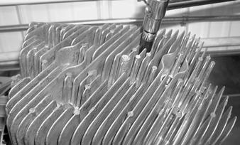
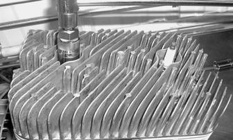
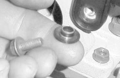
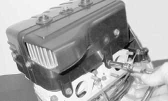
1.Remove the nuts, lock washers, and washers securing the intake flange assembly. Account for the gaskets, insulators, and the heat deflector. 2.Remove the five cap screws securing the front (exhaust-side) shroud to the cylinder head. Account for the special washers.
MD0276
NOTE: Keep the special mounting hardware with
the shrouds for assembling purposes. Cap screws securing the front and rear shrouds use special washers.
MD0065
3.Remove the spark plug grommets.
MD0060
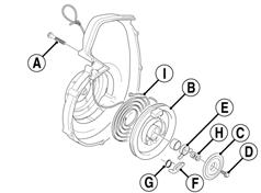
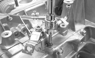
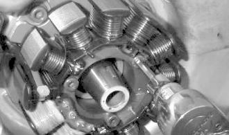
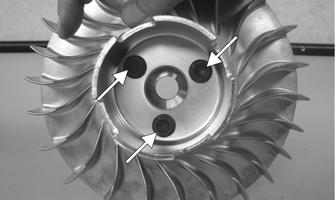
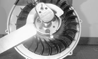
4.Using Flywheel Spanner Wrench to hold the starter clutch, remove the cap screw securing the flywheel to the crankshaft and account for the flat washer and lock washer.
MD0282
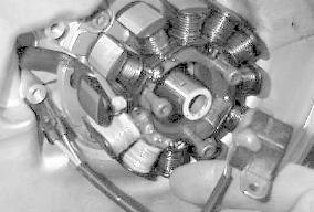
5.Using Flywheel Spanner Wrench to hold the starter clutch, remove the three cap screws securing the starter clutch to the flywheel assembly.

To prevent damage to the crankshaft, install a protective insert into the end of the crankshaft. The puller must bottom on the insert and not on the crankshaft. Also, do not thread puller bolts more than five threads into the flywheel. Damage to the stator coils may result.
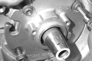
6.Using Flywheel Puller, remove the flywheel. NOTE: To ensure the cleanliness of the flywheel
magnets, place the flywheel (with the magnets facing upward) on a clean bench.
NOTE: Do not remove the fan from the flywheel
assembly. If any damage or failure occurs with the fan or the flywheel, it must be replaced as an assembly.
7.Remove the six cap screws securing the rear (intake-side) shroud; then remove the shroud.
Account for the special washers.
MD0277 MD0075
MD0073
9. Remove the three Allen-head cap screws securing the stator and remove it along with the timing sensor; then carefully pull the wires through the hole in the crankcase.
MD0067
8.Remove the rubber insulator grommet from the crankcase; then remove two Phillips-head cap screws securing the ignition timing sensor.

MD0072
MD0076
10.Remove the four Allen-head cap screws securing the stator plate. Remove the stator plate.
MD0255
MD0078
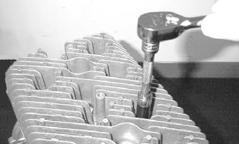
11.Remove the four cap screws securing the seal retainer plate on the PTO-side; then remove the plate. 13.Remove the eight cap screws, two nuts, and two washers securing the cylinder head to the cylinders; then remove the cylinder head. Discard the cylinder head gasket.
MD0289
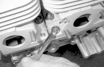
14.Remove the four 6 mm nuts and eight 10 mm nuts securing the cylinders to the crankcase. NOTE: Using a felt-tip marker, mark the cylinders
as to MAG-side and PTO-side for assembling. Also, mark the pistons at this time.
MD0081
12.Remove the spark plugs.
MD0083 MD0087

MD0086
15.Remove the cylinders making sure to support the pistons so they are not damaged. Account for four dowel pins.
CAUTION
When removing a cylinder, make sure to support the piston so it will not be damaged.
MD0230

MD0096
16.Using an awl, remove the outside piston-pin circlip and remove the piston pin using Piston Pin Puller.
MD0094

NOTE: The shoulder sides of the piston pin bearing
washers must seat to the bearing.

MD0208
NOTE: Always replace with new piston rings and as
a complete set. Note the identification on the tapered side of each ring for installation purposes.
726-306A
MD0271
17. Remove the two Allen-head cap screws securing the oil-injection pump; then remove the pump. Account for an O-ring.
MD0251
MD0090
MD0092A
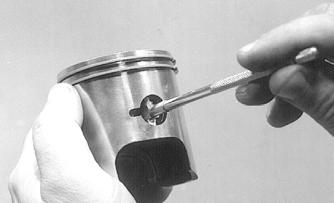
18.Remove the oil-injection pump driveshaft retainer.
Account for an O-ring.
MD0283
MD0100A
19.Remove the oil-injection pump driveshaft. Account for a thrust washer.

MD0101
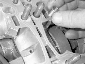
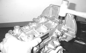
20.Place the crankcase (with its bottom side up) on two blocks of wood. Remove the 12 cap screws securing the crankcase halves. Note the location of the different-sized cap screws. 21.Separate the crankcase halves by installing two of the cap screws in opposite corners leaving the heads approximately 1/4 in. out. Using a plastic mallet, tap on each cap screw until the crankcase halves separate. Account for four dowel pins.
MD0204
22.Remove the two cap screws; then remove the crankshaft assembly from the upper crankcase half making sure to hold both ends of the crankshaft to keep the bearings and seals from falling off. Account for bearings and a C-ring.
CAUTION
To prevent damage to the crankshaft, crankshaft bearings, or seals, be sure to always lift the crankshaft from both ends.
Cleaning and Inspecting
CYLINDER HEAD 1.Using a non-metallic carbon removal tool, remove any carbon buildup from the combustion chambers being careful not to nick, scrape, or damage the combustion chambers or the sealing surfaces. 2.Inspect the spark-plug holes for any damaged threads. 3.Inspect the cylinder head for flatness using a straightedge and a feeler gauge. Acceptable warpage must not exceed 0.002in.
NOTE: If the warpage exceeds specification, resur-
face the cylinder head using procedures identified in step 4.

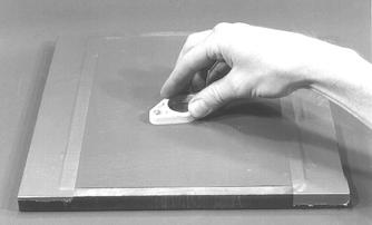
MD2491
4.Place the cylinder head on a Surface Plate covered with #400 grit wet-or-dry sandpaper. Using light pressure, move each cylinder head in a figure-eight motion. Inspect the sealing surface for any indication of high spots. A high spot can be noted by a bright metallic finish. Correct any high spots before assembly by continuing to move the cylinder head in a figure-eight motion until a uniform bright metallic finish is attained.
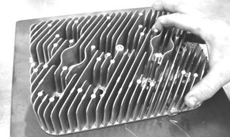
MD2492
CAUTION
Water or parts-cleaning solvent must be used in conjunction with the wet-or-dry sandpaper or damage to the sealing surface may result.
CYLINDERS 1.Using a non-metallic carbon removal tool, remove carbon buildup from the exhaust ports. 2.Wash the cylinders in parts-cleaning solvent. 3.Inspect the cylinders for pitting, scoring, scuffing, and corrosion. If marks are found, repair the surface with a Ball Hone and honing oil. NOTE: To produce the proper 45° crosshatch pat-
tern, maintain a low drill RPM. If honing oil is not available, use a lightweight, petroleum-based oil. Thoroughly clean the cylinders and reed valves after honing using detergent soap and hot water and dry with compressed air; then immediately apply oil to the cylinder bores. If a bore is severely damaged or gouged, the cylinder must be replaced.
4.Place the head surface of each cylinder on the surface plate covered with #400 grit wet-or-dry sandpaper. Using light pressure, move each cylinder in a figure-eight motion. Inspect the surface for any indication of high spots. A high spot can be noted by a bright metallic finish. Correct any high spots before assembly by continuing to move the cylinder in a figure-eight motion until a uniform bright metallic finish is attained.
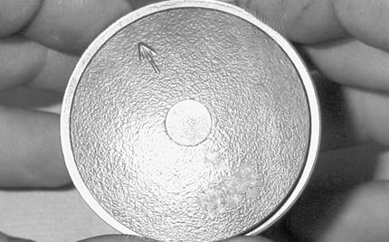
PISTON ASSEMBLY 1.Using a non-metallic carbon removal tool, remove the carbon buildup from the dome of each piston. 2.Take an old piston ring and snap it into two pieces; then grind the end of the old ring to a 45° angle and to a sharp edge. Using the sharpened ring as a tool, clean carbon from the ring-grooves. Be sure to position the ring with its tapered side up.
CAUTION
Water or parts-cleaning solvent must be used in conjunction with the wet-or-dry sandpaper or damage to the sealing surface may result.
CAUTION
Improper cleaning of the ring-grooves by the use of the wrong type of ring-groove cleaner will result in severe damage to the piston.
3.Inspect each piston for cracks in the piston pin and skirt areas. 4.Inspect each piston for seizure marks or scuffing. If scuffing or seizure marks are too deep, replace the piston. 5.Inspect the perimeter of each piston for signs of excessive “blowby.” Excessive “blowby” indicates worn piston rings or an out-of-round cylinder. CRANKCASE 1.Wash the crankcase halves in parts-cleaning solvent. NOTE: Before washing the crankcase halves, make
sure the four bearing dowel pins have been removed and accounted for.
2.Inspect the crankcase halves for scoring, pitting, scuffing, or any imperfections in the casting. 3.Inspect all threaded areas for damaged or stripped threads. 4.Inspect the bearing areas for cracks or excessive bearing movement. If evidence of excessive bearing movement is noted, the crankcase must be replaced. 5.Inspect the bearing dowel pins for wear. 6.Inspect the sealing surfaces of the crankcase halves for trueness by placing each crankcase half on the surface plate covered with #400 grit wet-or-dry sandpaper. Using light pressure, move each half in a figure-eight motion. Inspect the sealing surfaces for any indication of high spots. A high spot can be noted by a bright metallic finish. Correct any high spots by continuing to move the half in a figure-eight motion until a uniform bright metallic finish is attained.
NOTE: Care must be taken not to remove an exces-
sive amount of aluminum, or the crankcase must be replaced. If excessive aluminum is removed, too much preload will be exerted on the crankshaft bearings when assembled.
MD0200A
CAUTION
Water or parts-cleaning solvent must be used in conjunction with the wet-or-dry sandpaper or damage to the sealing surface may result.
INSULATOR PLATES 1.Inspect for cracks, scoring, pitting, imperfections, or warping. 2.Inspect the sealing surfaces for trueness by placing each on the surface plate covered with #400 grit wet-or-dry sandpaper. Using light pressure, move both sides in a figure-eight motion. Inspect the sealing surface for any indication of high spots or warping. Correct high spots by continuing to move each side in a figure-eight motion. Warped components must be replaced. NOTE: In order to inspect insulator plate trueness,
it will be necessary to remove the studs.
CAUTION
Water or parts-cleaning solvent must be used in conjunction with the wet-or-dry sandpaper or damage to the sealing surfaces may result.
A932
CRANKSHAFT NOTE: If any servicing of the connecting rods, cen-
ter bearings, or oil-injection pump drive gear is necessary, take the crankshaft to a qualified machine shop for that service.
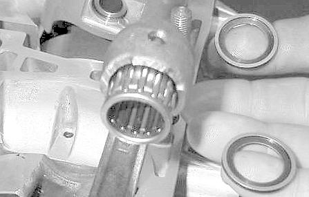
1.Wash the crankshaft with bearings in parts-cleaning solvent. 2.Inspect the bearings for wear, scoring, scuffing, damage, or discoloration. Rotate the bearings. Bearings must rotate freely and must not bind or feel rough. If any abnormal condition is noted, replace the bearing.

FC039
3.Inspect the connecting-rod bearings by rotating them. The bearings must rotate freely and must not bind or feel rough. If a connecting-rod bearing must be replaced, the connecting rod and crank pin must also be replaced.

FC040
4.Inspect the oil-injection pump drive gear for any signs of worn or chipped teeth. If either condition exists, replace the gear. NOTE: Lubricate bearings thoroughly prior to
assembly.
REMOVING OUTER CRANKSHAFT BEARINGS NOTE: Steps 1-2 are for removing the MAG-side
bearing.
1.Place the crankshaft in a suitable support; then install
Crankshaft Bearing Remover between the journal and the MAG-side bearing. 2.Place the protective cap on the crankshaft end; then remove the bearing from the end of the crankshaft.
Account for any shim(s). Note the position of the dowel pin hole.
AN068D
3.The PTO-side bearing may be removed simply by sliding the bearing off the PTO end.


AN151A
4.Inspect the crankshaft bearing area for wear. If any wear is noted on either end, replace the crankshaft end. INSTALLING OUTER CRANKSHAFT BEARINGS NOTE: Steps 1-3 are for installing the MAG-side
bearing.
1.Wrap a thick towel around the crankshaft; then secure the crankshaft vertically in a vise. 2.Heat the bearing either by placing the entire bearing in a pan of oil on a hot plate or by squirting oil into the bearing and using a propane torch to heat the inner race of the bearing until a slight smoke is noted coming from the bearing.
3.Place any shims removed during disassembly onto the crankshaft; then slide the bearing onto the crankshaft making sure the dowel-pin hole in the outer race is properly positioned and will align with its hole and pin in the crankcase. 4.Slide the PTO-side bearing onto the PTO end making sure the dowel-pin hole will align with the hole and pin in the crankcase.
CAUTION
DO NOT overheat the bearing.
AN151A
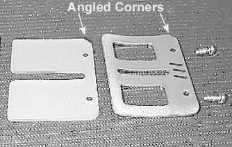
REED VALVE ASSEMBLY 1.Inspect the reed valves, stoppers, and cages for cracks or any deterioration. 2.Wash the reed valves, stopper, and cage assembly in parts-cleaning solvent and blow dry. 3.Inspect the reed stopper height. Using a caliper, measure the distance from the seat to the bottom outer tip edge of the stopper. Measurement must not exceed 0.236 in. If measurement is not within specifications, either bend or replace the reed stopper. 4.Inspect the reed-to-seat clearance. Using a feeler gauge, measure the clearance. Clearance must be less than 0.008in. If clearance is not within specifications, replace the reed valve. 5.To assemble, place the reed valves on the cage with its angled corner positioned to the lower right hand corner of the cage. Place the reed stopper assembly into position and secure with the three machine screws coated with blue Loctite #243. Tighten the machine screws to 48 in.-lb.
MD0213
CAUTION
Do not over-tighten the machine screws when installing the reed valves and reed valve stoppers.
6.When installing the reed valve cage, use blue Loctite #243 on the cap screws and tighten to 96 in.-lb.
Measuring Critical Components
CYLINDER HEAD VOLUME (Squish-Gap Method) To check the squish gap, a micrometer and two heavy pieces of solder will be needed. 1.Remove the spark plugs from the engine. 2.Simultaneously insert two pieces of solder down through the spark plug hole and push them up against the inner cylinder bore toward the MAG-side and
PTO-side of the cylinder. 3.Pull the recoil rope and crank the engine over several times while the solder is being held firmly in place. 4.Remove both pieces of solder from the cylinder.
Using the micrometer, measure the very end of the squeezed solder piece. Record the reading. NOTE: If the solder hasn’t been squeezed by the
piston, a larger piece of solder must be used. Repeat procedure.
5.Using the opposite end of the solder pieces, insert them down through the spark plug hole toward the
PTO-side and MAG-side of the cylinder. Push on the solder until they contact the inner cylinder bore. 6.Pull the recoil rope and crank the engine over several times. Remove both pieces of solder from the cylinder and measure the opposite squeezed ends with a micrometer. Record reading. NOTE: Measure from PTO to MAG-side of the pis-
ton to accurately measure the squish gap. Never measure across piston, exhaust to carburetor side, as the piston will rock and the reading won’t be accurate.
Readings may vary from side to side. NOTE: Make sure the smaller reading is 0.066 in. or
less.
CYLINDER TRUENESS 1.Measure each cylinder in the three locations from front to back and side to side for a total of six readings.

MD2493
2.The trueness (out-of-roundness) is the difference between the highest and lowest reading. Maximum trueness (out-of-roundness) must not exceed 0.004 in.
0725-586
PISTON SKIRT/CYLINDER CLEARANCE 1.Measure each cylinder front to back about 1in. from the bottom of each cylinder. 2.Measure the corresponding piston skirt diameter at a point 1 cm above the piston skirt at a right angle to the piston-pin bore. Subtract this measurement from the measurement in step 1. The difference (clearance) must be within 0.0031-0.0041 in.
AC091
PISTON-RING END GAP 1.Place each piston ring in the wear portion above the exhaust port of its respective cylinder. Use the piston to position each ring squarely in each cylinder. 2.Using a feeler gauge, measure each piston-ring end gap. Acceptable ring end gap must be within 0.0120-0.0196 in.
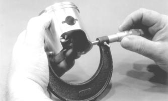
PISTON PIN AND PISTON-PIN BORE 1.Measure the piston pin diameter at each end and in the center. Acceptable piston pin measurement must be within 0.7085-0.7087 in. If any measurement varies by more than 0.001in., the piston pin and bearing must be replaced as a set.

IO012
2.Insert a snap gauge into each piston-pin bore; then remove the gauge and measure it with a micrometer.
The diameter measurement must be within 0.7087-0.7091 in. Take two measurements to ensure accuracy.
AC092
CONNECTING-ROD SMALL END BORE 1.Insert a snap gauge into each connecting-rod small end bore; then remove the gauge and measure it with a micrometer.

AN061
2.The diameter measurement must be within 0.9056-0.9059 in.
0742-727
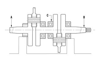
1.Using V Blocks, support the crankshaft on the surface plate. NOTE: The V blocks should support the crankshaft
on the outer bearings.
2.Mount a dial indicator and base on the surface plate.
Position the indicator contact point against the crankshaft location point A (PTO-end) from the crankshaft end. Zero the indicator and rotate the crankshaft slowly. Note the amount of crankshaft runout (total indicator reading). NOTE: For runout location point specifications, see
Crankshaft Runout/Repair Specifications in General Information/Foreword section of this manual.
3.Position the indicator contact point against the crankshaft location point B (MAG-end) from the crankshaft end. Zero the indicator and rotate the crankshaft slowly. Note the amount of crankshaft runout (total indicator reading).

FC046
4.Position the indicator contact point against the crankshaft at location point C (center). Zero the indicator and rotate the crankshaft slowly. Note the amount of crankshaft runout (total indicator reading). 5.If runout exceeds 0.002 in. at any of the checkpoints, the crankshaft must be either straightened or replaced.
Assembling
NOTE: Use new gaskets and seals when assembling
the engine.
NOTE: Prior to assembling the engine, use parts
cleaning solvent and compressed air and thoroughly clean the threaded holes of the crankcase and cylinders to properly tighten.
! WARNING
Always wear safety glasses when drying components with compressed air.
NOTE: When the use of a lubricant is indicated, use
recommended Arctic Cat Injection Oil.
1.Place the upper crankcase half (with its bottom side up) on two blocks of wood.
CAUTION
To prevent damage to the crankshaft, crankshaft bearings, or seals, make sure to always lift the crankshaft from both ends.
2.Lightly grease the inner lips of the crankshaft seals; then slide them onto the crankshaft. 3. Apply oil to the crankshaft bearings; then install the crankshaft into the upper crankcase half. Be sure the alignment hole in each bearing is positioned over its respective dowel pin in the crankcase; then seat the crankshaft.
NOTE: To check the bearing for proper position,
place the point of a sharp tool into the dimple found in the bearing race. Strike the tool with the palm of the hand in either direction. If the bearing moves, it isn’t positioned correctly and must be rotated until it drops onto the dowel pin.
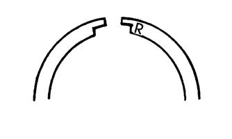
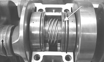
NOTE: Position the two center seal rings with their
end gaps 180° apart (up on one and down on the other); then apply a thin coat of High-Temp Sealant to the entire bottom half of the crankcase sealing surface.
CAUTION
If the bearings are not properly seated during assembly, the crankcase halves will not seal tightly and severe engine damage will result.
CM036A
4.Install the four crankcase dowel pins. 5.Install crankcase lower half. Install eight 8 mm and four 6 mm cap screws. 6.Tighten the 8 mm cap screws in two steps to 17 ft-lb and the 6 mm cap screws to 96 in.-lb using the pattern shown.
737-027A
MD0212
NOTE: Check the reed valve on each cylinder.
Make sure they are clean and closing completely.
7. Install the piston rings on each piston so the letter on the top (inclined surface) of each ring faces the dome of the piston.
726-306A
CAUTION
Incorrect installation of the piston rings will result in engine damage. Always replace rings as a complete set.
8.Lubricate the piston pin bearings and install them into the connecting rods.
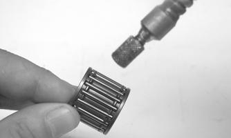

TZ068
9. Install piston pin bearing washers on each side of the bearing with the shoulder side facing the bearings. NOTE: The shoulder side of the piston pin bearing
washers must face the bearing.
MD0251
10. Place pistons over the connecting rods with the arrow (or indicator dot) pointing toward the exhaust port; then secure with an oiled piston pin. Install new piston pin circlips with the open ends up or down.
MD0293
NOTE: To aid in the circlip installation, install the
circlip to the inside of the piston before installing the connecting rod.
MD0248
CAUTION
Make sure the new circlips are firmly seated in their grooves and the open ends are pointed up or down before continuing with assembly.
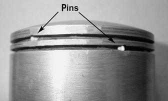
11.Place the cylinder base gasket into position on the crankcase making sure the gasket is properly oriented so the dowel pins will fit through the holes easily. 12. Rotate each piston ring until the ring ends are properly positioned with the pins in the ring grooves; then apply oil to the piston assemblies and cylinder bores.
Using a ring compressor or the fingers, compress the rings and slide the cylinder over the piston. Seat the cylinder firmly onto the crankcase.
MD0271
CAUTION
The cylinders should slide on easily. DO NOT force them on or component damage may occur.
MD0229
13.Secure each cylinder by installing the four 6 mm and eight 10 mm nuts. Tighten the 10 mm nuts in a crisscross pattern to 44 ft-lb and the 6 mm nuts to 96 in.-lb.

MD0086
14.Install a new cylinder head gasket and the cylinder head; then install the eight cap screws and two flange nuts. Tighten the cap screw in three steps to 19 ft-lb using the pattern shown; then tighten the flange nuts to 21 ft-lb.
MS384
MS384
0738-291
15.Install the spark plugs. Pressure test the engine (see
Engine-Related Items section).
16.Position the seal retainer plate on the PTO-side; then install the four cap screws. Tighten the cap screws to 96 in.-lb.

MD0253 MD0076

MD0292
17.Install the stator plate so the ignition wire cut-out is in the upper left position. Lightly coat the four
Allen-head cap screws with blue Loctite #243; then install and tighten them to 96 in.-lb.

MD0274
19.Place the ignition timing sensor wiring through the hole in the crankcase; then position the ignition timing sensor and install two Phillips-head cap screws (coated with blue Loctite #243). Tighten the cap screws to 48 in.-lb.
MD0255
18.Place the stator wiring through the hole in the crankcase; then install the stator. Lightly coat the three
Allen-head cap screws with blue Loctite #243; then tighten to 48 in.-lb.
MD0074
MD0073
20.Install the rubber insulator grommet into the crankcase.
MD0262
21.Place the starter clutch into position on the flywheel assembly; then tighten the cap screws only until snug. 22.Install the key; then install the flywheel and cap screw (threads coated with blue Loctite #243) w/lock washer and flat washer; then using Flywheel Spanner
Wrench to hold the starter cup, tighten the flywheel cap screw to 50 ft-lb.

TZ067A
24.Using the six cap screws and the special washers, install the rear (intake-side) shroud. Tighten the cap screws (coated with red Loctite #271) to 96 in.-lb.

MD0264 MD0277
25.Using the five 6 mm cap screws and the special washers, install the front (exhaust-side) cooling shroud and tighten to 96 in.-lb. Install the rubber spark plug grommets; then tighten the cap screws securely.

MD0278
23.Using Flywheel Spanner Wrench to hold the starter cup, tighten the three cap screws (from step 21) to 28 ft-lb.
MD0269
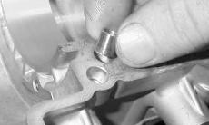
26.Lubricate the oil-injection pump driveshaft; then while rotating the driveshaft, install it and the thrust washer into the lower crankcase half.
NOTE: When installing the oil-injection pump
driveshaft, make sure the thrust washer is installed.
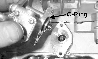
28.With a new O-ring (lightly coated with oil) in place, install the oil-injection pump aligning the slot on the oil pump with the flat on the end of the oil-injection pump driveshaft. Tighten the Allen-head cap screws (coated with blue Loctite #243) to 48 in.-lb.
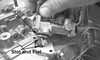
MD0252
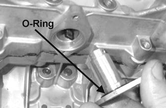
27.With a new O-ring (lightly coated with oil) in place, install the oil-injection pump driveshaft retainer.

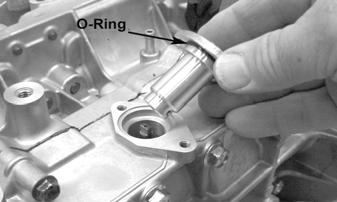
MD0273 MD0294
29.Install the first set of intake gaskets (coated with
High-Temp Sealant), heat deflector, remaining gaskets, insulators, and flanges. Secure with nuts and washers and tighten the nuts (threads coated with red
Loctite #271) to 15 ft-lb.
Troubleshooting Engine
Problem: Engine Does Not Start (No Spark at Spark Plugs) Condition Remedy
1. Ignition switch malfunctioning — not in RUN position 1.Replace ignition switch — turn switch to RUN position 2. Wiring harness shorting — connection poor 2.Repair — connect — replace wiring harness 3. Emergency stop switch knob in DOWN position — 3.Move knob to UP position — replace throttle switch malfunctioning 4. Throttle/ignition monitor switch adjusted too tight — 4.Adjust (loosen) throttle cable — replace throttle switch malfunctioning 5. Carburetor safety switches adjusted incorrectly — 5.Adjust — replace carburetor safety switches malfunctioning 6. Spark plugs fouled — damaged 6.Clean — gap — replace spark plugs 7. Spark-plug caps damaged — leaking — shorting 7.Replace spark-plug caps 8. High tension wires/coil loose — grounded — faulty 8.Service — replace high tension wires/coil 9. CDI unit faulty 9.Replace CDI unit 10. Charge coil (1) faulty 10.Replace coil 11. Charge coil (2) faulty 11.Replace coil 12. Flywheel magnets weak 12.Replace flywheel 13. Flywheel key sheared 13.Replace key
Problem: Engine Does Not Start (No Fuel at Cylinders) Condition Remedy
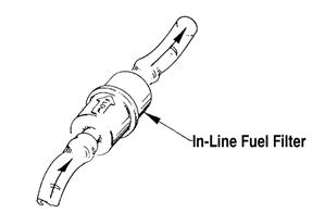
1. Gas tank empty 1.Fill tank 2. Shut-off valve closed 2.Open shut-off valve 3. Fuel hose broken — pinched 3.Replace — service hose 4. Gas-tank vent — hose obstructed 4.Remove obstruction — replace vent — hose 5. In-line fuel filter obstructed — damaged 5.Remove obstruction — replace in-line fuel filter 6. Fuel pump malfunctioning — faulty 6.Replace — repair — clean fuel pump 7. Impulse hose cracked — broken — pinched — 7.Replace — connect impulse hose disconnected 8. Carburetors adjusted incorrectly — dirty — damaged 8.Troubleshoot — clean — replace carburetors 9. Primary compression (crankcase) absent 9.Repair — replace damaged — worn engine components
Problem: Engine Overheats Condition Remedy
1. Spark plug heat range too hot 1.Install lower heat-range spark plugs 2. Coolant low — absent 2.Add coolant 3. Carburetors adjusted incorrectly — jetted incorrectly — 3.Troubleshoot — clean carburetors — jet correctly dirty 4. Carburetor-to-cylinder air leak 4.Replace — repair gaskets — intake flanges — service intake ports 5. Heat exchangers no snow for cooling 5.Select new trail — install ice studs to chew up hard packed snow and ice 6. Rings/grooves carboned 6.Clean — replace rings — pistons 7. Exhaust ports obstructed 7.Remove obstruction 8. Muffler obstructed 8.Remove obstruction 9. Gas/air mixture incorrect 9.Replace jets — adjust jet needle E-clip position 10. Oil-injection pump malfunctioning — adjusted incorrectly 10.Replace — bleed — adjust oil-injection pump 11. Primary compression (crankcase) low — absent 11.Repair — replace damaged — worn engine components 12. Ignition timing adjusted incorrectly 12.Time ignition 13. Gasoline octane too low 13.Use 87 minimum octane gasoline 14. Water pump — thermostat damaged — faulty 14.Replace — rebuild water pump — replace thermostat
Problem: Engine Backfires Condition Remedy
1. Throttle/ignition monitor switch adjusted incorrectly 1.Adjust throttle cable free-play — service spring 2. Spark plugs fouled — damaged 2.Clean — gap — replace spark plugs 3. Spark plug heat range too hot 3.Install lower heat-range spark plugs 4. High tension wires/coil shorting 4.Service — replace high tension wires/coil 5. Carburetor-to-cylinder air leak 5.Repair — replace gaskets — intake flanges service intake ports 6. Carburetors adjusted incorrectly — dirty — damaged — 6.Troubleshoot — tighten carburetors loose 7. Gas/air mixture incorrect — too lean 7.Adjust jetting 8. Oil-injection pump malfunctioning — adjusted incorrectly 8.Replace — bleed — adjust oil-injection pump
Problem: Engine Four-Cycles (Floods Excessively) Condition Remedy
1. Carburetors adjusted incorrectly — dirty — damaged 1.Troubleshoot — clean carburetors 2. Gas/air mixture incorrect 2.Adjust jetting 3. Oil-injection pump malfunctioning — adjusted incorrectly 3.Replace — bleed — adjust oil-injection pump 4. Air silencer obstructed 4.Remove obstruction
Problem: Engine Stops Gradually Condition Remedy
1. In-line fuel filter obstructed — damaged 1.Remove obstruction — replace in-line fuel filter 2. Fuel hose obstructed — broken — pinched 2.Remove obstruction — replace — repair fuel hose 3. Head gasket(s) burned out 3.Replace head gasket(s) — service cylinders — head 4. Cylinder head loosening 4.Tighten cylinder head cap screws 5. Spark plugs loose 5.Tighten spark plugs 6. Impulse hose cracked 6.Replace impulse hose 7. High tension wires/coil faulty 7.Service — replace high tension wires/coil
Problem: Engine Stops Suddenly Condition Remedy
1. In-line fuel filter obstructed — damaged 1.Remove obstruction — replace in-line fuel filter 2. Fuel hose obstructed — broken — pinched 2.Remove obstruction — repair — replace fuel hose 3. CDI unit faulty 3.Replace CDI unit 4. Ignition coil faulty 4.Replace ignition coil 5. Charge coil (1) faulty 5.Replace coil 6. Charge coil (2) faulty 6.Replace coil 7. Gas-tank vent — hose obstructed — damaged 7.Remove obstruction — replace vent — hose 8. Engine seized 8.Service engine 9. Throttle/ignition monitor switch faulty — throttle cable 9.Replace throttle control — adjust throttle cable free-play — adjusted incorrectly adjust — connect — replace carburetor safety switches
Problem: Engine Fails to Stop (Continues to Run, Even with All Switches Off) Condition Remedy
1. CDI unit shorted to ground 1.Replace CDI unit 2. Main wiring harness four-prong connector disconnected 2.Connect four-prong connector *Do not adjust the idle RPM screw