70 minute read
Suspension

NOTE: Whenever a part is worn excessively,
cracked, or damaged in any way, replacement is necessary.
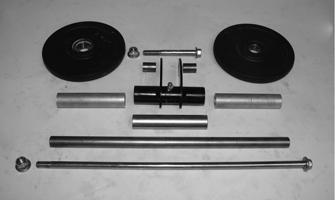
SPECIAL TOOLS A number of special tools must be available to the technician when servicing the rear suspension. NOTE: When indicated for use, each special tool
will be identified by its specific name, as shown in the chart below, and capitalized.
Description p/n
Shock Absorber Air Pump 2603-614 Piston Location Tool 0644-169 Idler Wheel Puller Kit 0644-570 Inflation Needle 0744-020 Rear Suspension Spring Tool 0144-311 Gas Shock Retaining Blocks (Zero Pro) 0644-486 Spanner Wrench — FOX Float Shock 0744-072 Handlebar Stand 5639-152 Steering Post Stand 5639-946 Bearing Cap Seal Protector 0644-268 Floating Piston Location Gauge 0644-350 Axle Nut Spanner Wrench 0644-454
NOTE: Special tools are available from the Arctic
Cat Service Parts Department.
UNDERSTANDING THE SUSPENSION Quick acceleration and the ability to go through the turns with power are the most important handling qualities. This section explains how the skid frame functions to provide these two important handling qualities. Before proceeding, however, note these terms. Weight Transfer — A shift in the center of gravity in any direction depends on the force applied. Track Tension — The amount of tightness or looseness of the track when correctly mounted in the chassis. Spring Tension — The amount of force exerted on the spring by either fork tension adjustment or eyebolt adjustment. Ski Pressure — The amount of force exerted downward on the skis. Good weight transfer characteristics are needed for fast acceleration (shift of weight from skis to track) and for cornering (shift of weight back to skis to hold the front end in turns). Effective weight transfer depends on suspension tension, position of rider, and the position of the front arm limiter. To understand how the suspension system works, think of the entire system in terms of three points; the skid frame rear axle center, the skid frame front arm, and the ski saddle center. Assume that the front arm functions as a stationary pivot point between the rear axle center and the ski saddle center. Also assume that the ski saddle center is the same height off the ground as the rear axle center. This produces the standard position arrangement.
0728-180
Under acceleration when the center of gravity is transferred to the rear of the machine, the rear suspension collapses slightly. This brings the rear arm point downward and with the front arm stationary, the teeter-totter effect reduces the pressure on the skis, position A. However, for controlled cornering, more pressure is needed on the skis. So when the driver decelerates coming into a corner, the center of gravity is transferred forward, putting the required pressure onto the skis and reducing the pressure on the rear suspension, position C.
0728-181
This is essentially what weight transfer is all about the shift of weight to the rear of the machine for positive traction and good acceleration or to the front of the machine for positive handling and cornering control.
Suspension Setup Basics
SKI SHOCK ABSORBER SPRINGS The shock absorber springs have been matched to the shock valving and rear suspension. These springs are the result of hours of testing and comparison riding trying many different combinations of springs and shocks. If changes are necessary, several spring and shock sizes are available. While making these changes, keep the following points in mind.
Heavier Or Stiffer Springs 1.These will require shocks with more rebound control, or the front end will become like a pogo stick. 2.With stiffer springs, the front end will become more aggressive in the corners as more weight will be transferred to the skis when decelerating. Also, more weight is transferred to the rear on acceleration and can cause the rear shocks and spring to bottom out. 3.If the springs are too stiff for general riding conditions and style, the ride comfort is gone. Spring Tension Too Soft 1.Front end bottoms out; hard on front end parts. 2.Less aggressive steering in corners on deceleration, and less weight is transferred to the skis because of softer springs. 3.Less weight gets transferred to rear of the machine upon acceleration. NOTE: When softening the ski springs, also soften
the rear to match entire suspension.
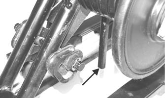
FRONT ARM SPRING TENSION Having very light front arm spring tension is desirable. When riding in 4 in. or more of snow, the machine will be quicker if the front spring tension is adjusted lightly. If the spring tension is adjusted too stiff, the track angle at the front of the skid frame is steep. This steep angle prevents the snowmobile from getting up on plane and slows down by 5 to 8 mph. Also, the following could occur. 1.Slows machine down in loose snow. 2.Causes the snowmobile to dart and dive as a result of less track on the ground on deceleration. NOTE: A tight front arm works well under only two
conditions: sticky snow conditions in the spring of the year and in hill climbing on hard packed snow.
With the front arm adjusted too soft, the spring may come off the roller. When riding in sticky snow (springtime or warm days) or hill climbing on hard snow, it may be desirable to stiffen the front arm spring tension. When this is done, weight is transferred back quicker. The problem with too much front arm spring tension is that the feel of the snowmobile becomes very short. The reason for this is the front arm becomes the pivot point between the spindles and rear of the snowmobile. With dominant spring tension on the front arm, the suspension is basically contacting the snow from a point below the front arm to the skis or the spindle pressure point. This makes for a very short and darting snowmobile on the trail. This is especially true when decelerating and the center of gravity is transferred forward. A method for adjusting the front spring tension follows.
CAUTION
If the ski shock spring is adjusted too loose, the spring retainer may fall out. If the spring is adjusted beyond specification, the spring will coil bind and spring adjuster damage will occur.
0729-662
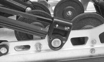
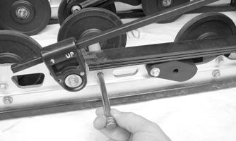
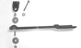
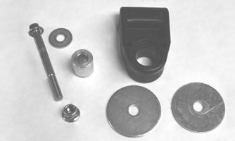
FRONT ARM LIMITER STRAPS Under no circumstances should the front arm limiter strap be lengthened. If lengthened, it may cause shock absorber travel problems. The two limiter straps can be shortened to suit driving style and some test driving time. With the rear arm in its present mounting location, no advantage has been noted from changing the strap length. If the front arm straps are shortened, the result will be more ski pressure and aggressive steering. OVERLOAD SPRINGS Some models have overload springs built into the rear suspension. When either carrying a heavy load or riding 2-up, the overload springs should be engaged by rotating the spring tension blocks to the UP position. The spring tension blocks lock in an over-center position when engaged. NOTE: Arctic Cat recommends that the overload
springs be engaged whenever a load on the snowmobile (operator/passenger/cargo) exceeds 136 kg (300 lb).
CAUTION
There are weight limitations for these snowmobiles. If additional cargo is being added, maximum weight on the snowmobile (operator/passenger/cargo) should not exceed the maximum limitation set for each snowmobile. See chart for details. Also, the overload springs should be engaged.
Maximum Weight Limitations
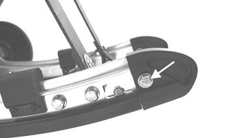
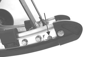
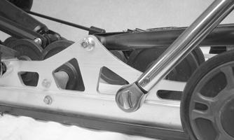
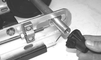
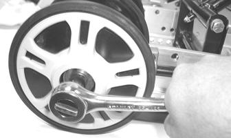
Bearcat 2000 XT 272 kg 600 lb Lynx 2000 LT 170 kg 375 lb To either engage or disengage the spring tension blocks, use a spark plug socket and a screwdriver to adjust the spring block to the desired position. Make sure both spring blocks are in the same position (either engaged or disengaged).
744-457A
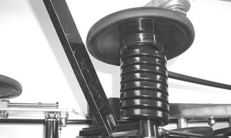
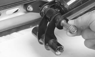
REAR ARM SPRING TENSION The rear spring tension is adjusted for the weight of the driver. Three possible adjustments exist. 1st block position — set for up to 150 lb 2nd block position — set for 150 to 200 lb 3rd block position — set for over 200 lb
727-720A
NOTE: When making any changes to the front or
rear suspension, the change should be made at both ends to keep the suspension balanced. For example, installing stiffer springs in front may require installing the next step stiffer spring in back to keep everything in balance.
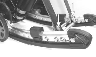
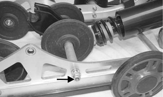
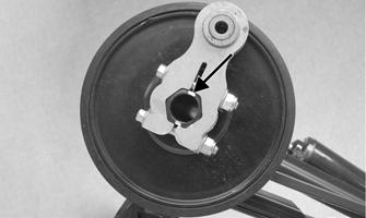
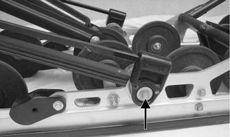
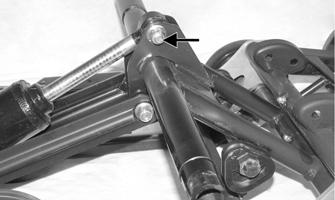
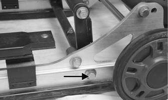
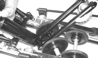
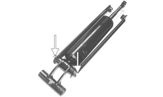
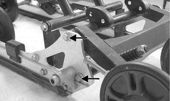
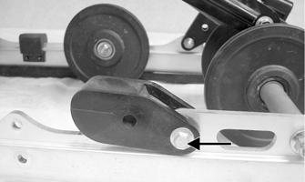
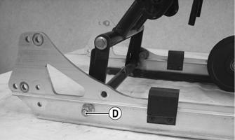
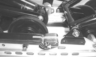
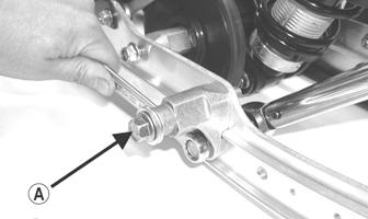
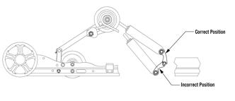
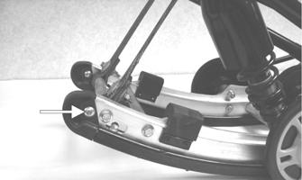
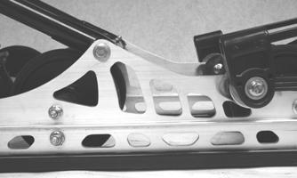
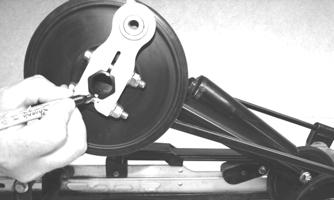
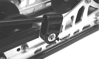
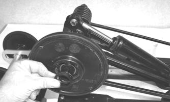
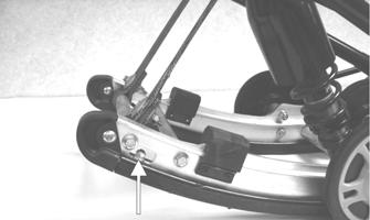
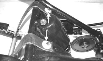
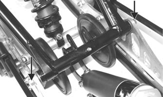
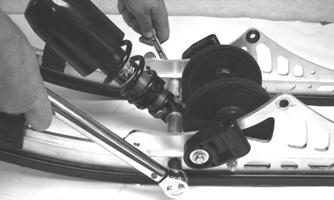
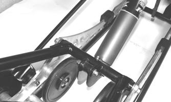
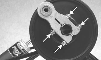
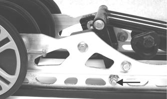
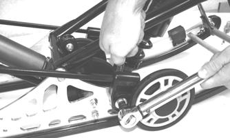
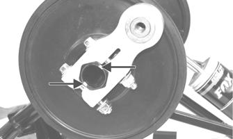
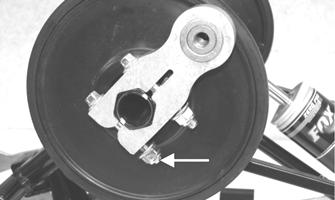
ADJUSTING REAR ARM COUPLER The rear arm coupler provides advantages over the standard suspension. First, with the coupler system, ski lift under acceleration is greatly reduced which provides improved handling. Second, when riding through rough terrain, the rear suspension arm receives some needed assistance from the front arm shock and spring as the rear arm is fully collapsed and locked up by the coupler blocks. The front arm then starts to collapse the shocks and spring which assist the rear springs. The result is a smoother ride for the operator. If additional coupler action is desired, the coupler blocks can be set to the number 2 or 3 position. Each of the coupler blocks has three positions numbered on the inside surface of the block. When changing the block position, change both to the same number. To make the coupler adjustment, follow the procedure below. 1.Loosen the two cap screws that secure the coupler blocks to the inside of the suspension rails.
0747-212
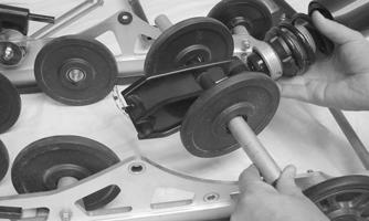
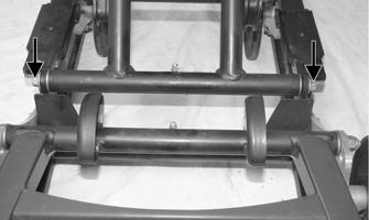
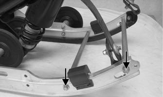
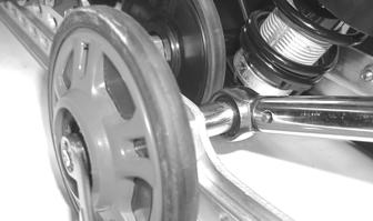
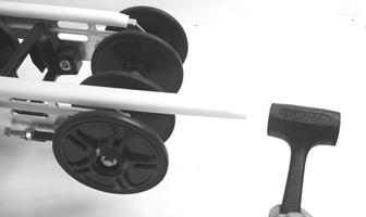
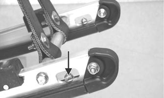
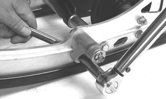
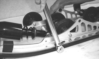
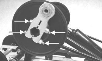
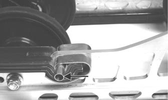
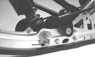
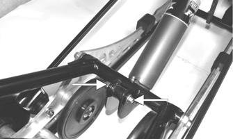
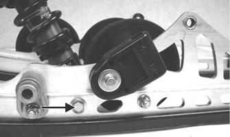
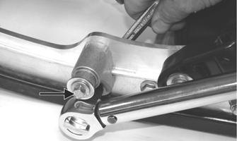
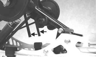
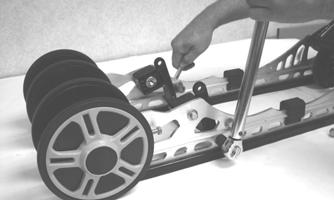
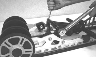
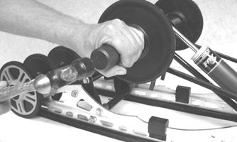
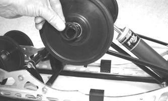
3.Place a 4-in. block of wood under the rear of the suspension just in front of the rear idler wheels to assist in collapsing the suspension. 4.Collapse the rear suspension until the rear arm is firmly against the coupler blocks aligning the two blocks squarely with the arm. While in this position, tighten the two cap screws securely.
Pressurizing Rebuildable Shocks
To pressurize the gas shock absorber, a regulator system and a nitrogen tank will be needed. ! WARNING
Never have a nitrogen bottle in the area without having it chained or secured. If the bottle should tip over and the regulator break off, the gas inside it is under 1800 lb of pressure and personal injury may result.
! WARNING
Always rotate the regulator T-handle to its loose position each time when finished using the system. Each time before the nitrogen tank valve is opened, check to make sure the regulator T-handle is turned out. When opening the nitrogen tank valve, never stand in front of the regulator in case there should be a problem.
NOTE: Before inserting the needle into the bladder,
lubricate the needle with light oil to make installation easier.
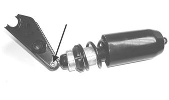
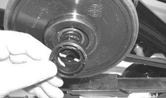
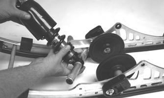
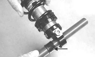
1.Insert the Inflation Needle into the shock bladder; then open the valve on the filler handle. 2.Turn the nitrogen tank valve open and slowly rotate the regulator T-handle inward until the gauge reads 200 lb of pressure; then close filler valve and remove inflation needle. 3.Install the screw or the air valve ball (FOX Float
Shock) into the bladder housing and tighten securely. 4.With the reservoir pressurized, push down on the shock shaft until it nearly bottoms and release it. The shaft should return to its extended position smoothly.
NOTE: If a soft spot or a mushy area is felt as the
shaft is pushed down, this would indicate air in the shock body. If there is air in the shock body, discharge the reservoir gas pressure. Disassemble the shock to the point that the “filling with oil” and the “bleeding air” procedures can be redone. Assemble and repeat the pressurizing procedure. To test the shock absorber for nitrogen gas leaks, submerge in water.
Servicing Suspension (Bearcat 2000 XT)
This sub-section has been organized so each procedure can be completed individually and efficiently. NOTE: Some components may vary from model to
model. The technician should use discretion and sound judgment when removing and installing components.
Removing Skid Frame
NOTE: Many service procedures can be performed
without removing the skid frame. The technician should use discretion and sound judgment when removing and installing components.
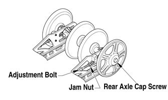
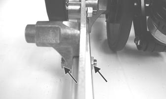
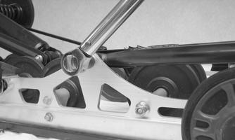
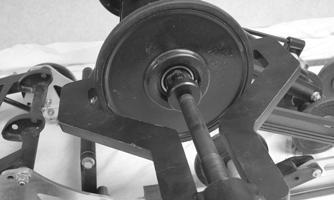
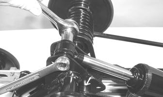
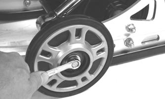
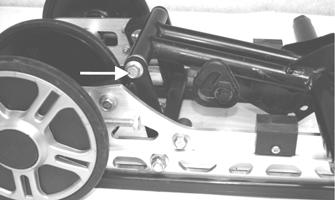
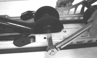
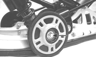
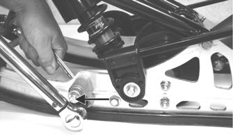
1.To avoid having the adjuster bushings binding during removal, remove the rear idler wheel caps and loosen the cap screws on the rear axle.
0742-921
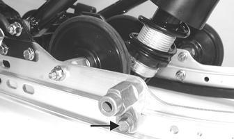
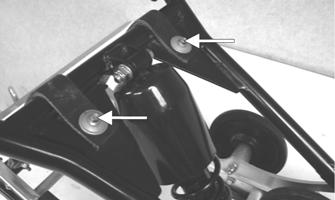
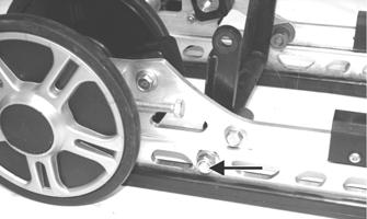
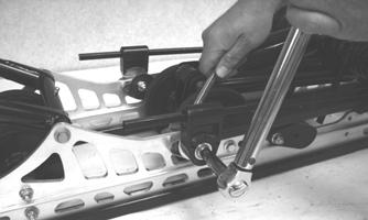
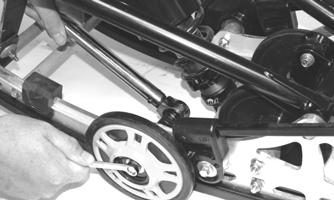
2.Loosen the jam nuts and two track-tension adjusting bolts of the articulating skid frame. 3.Place a support stand under the rear bumper; then while holding the flared bushing, remove the rear mounting cap screws securing the skid frame to the tunnel.
NOTE: The support stand should hold the snowmo-
bile level but not raised off the floor.
4.Remove the front cap screws securing the skid frame to the tunnel. Account for a flat washer and a lock washer.
5.Remove the support stand; then using an appropriate handlebar/steering post support stand, tip the snowmobile onto one side. Remove the skid frame.
End Caps
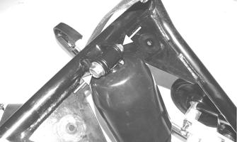
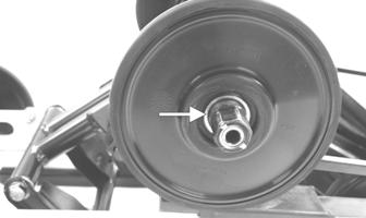
REMOVING 1.Remove the lock nut and cap screw securing the end cap.
MS016A
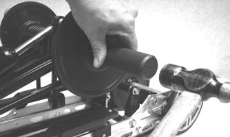
2.Using a hammer, tap the end cap off the rail. CLEANING AND INSPECTING 1.Inspect the end cap area of the slide rail for cracks and wear.
2.Inspect the end cap for any signs of cracking or wear. 3.Clean both the slide rail area and the end cap. Using compressed air, clean the areas of dirt and gravel.
4.Inspect the cap screw for cracked, stretched, or damaged threads. Use a new lock nut when assembling. INSTALLING 1.Position the end cap on the slide rail; then align the hole in the end cap with the hole in the slide rail. 2.Secure with a cap screw and lock nut. Tighten to 80 in.-lb. ! WARNING
Always wear an approved pair of safety glasses when using compressed air.
Wear Strips
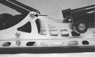
REMOVING 1.Remove the machine screw and lock nut securing the wear strip to the front of the slide rail.
MS016B
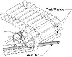
2.Align the wear strip with the openings (windows) in the track; then using a suitable driving tool, drive the wear strip rearward off the slide rail.
739-884A
CLEANING AND INSPECTING 1.Clean the slide rail using parts-cleaning solvent and compressed air.
! WARNING
Always wear an approved pair of safety glasses when using compressed air.
2.Inspect the slide rail for cracks. If any cracks are found, replace the slide rail. 3.Using a straightedge, inspect the slide rail for any unusual bends. With the slide rail removed, place the straightedge along the bottom surface of the slide rail.
If the rail is found to be bent, it must be replaced. INSTALLING NOTE: Use a file to remove any sharp edges on the
lower portion of the rail.
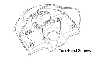
1.Align the wear strip with the openings (windows) in the track and from the back, start the wear strip onto the rail; then using a block of wood and a hammer, drive the wear strip forward into position. 2.Secure with a machine screw and lock nut. Tighten to 50 in.-lb. REMOVING 1.Using a 3/16-in. drill bit, drill out the rivets securing each front shock pad to the slide rail. Account for the retaining brackets. 2.Remove the torx-head screws and lock nuts securing the rear shock pads to the slide rail; then remove the shock pads. INSPECTING 1.Inspect the pad and retaining brackets for damage or wear. 2.Inspect the rivet holes in the slide rail for damage or elongation. INSTALLING 1.Place the front and rear pads and retaining brackets into position on the slide rail. 2.Secure the pads with rivets.
Idler Wheels/Mounting Blocks
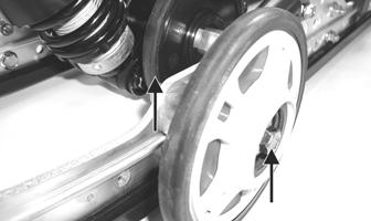
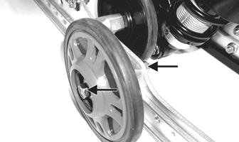
REMOVING Remove the cap screws and lock nuts securing the front outer idler wheel and mounting block. Account for the washer.
MS208
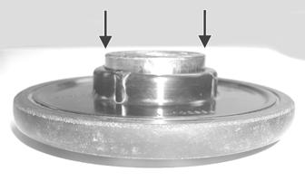
CLEANING AND INSPECTING 1.Clean the bearing with a clean cloth. 2.Inspect each idler wheel and each plastic hub for cracks or damage. 3.Rotate the idler wheel bearing (by hand) and inspect for binding or roughness. 4.If a bearing must be replaced, use this procedure.
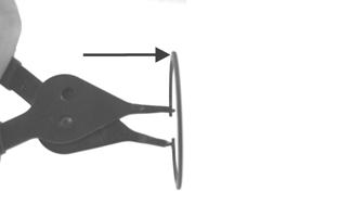
A.Remove the snap ring.
B.Using a hydraulic press, press the bearing out the inside of the wheel.
C.Press the new bearing (on its outer race) into the idler wheel.
MS006A
D.Install the snap ring making sure the “sharp side” is directed away from the bearing.
MS007A
INSTALLING 1.Secure each idler wheel mounting block on the slide rail with a cap screw and lock nut. Tighten to 20 ft-lb. NOTE: For proper alignment, install an idler wheel
cap screw into the top mounting block hole prior to tightening.
MS009A
2.Place the idler wheel against the mounting block making sure the washer is on the outside of the idler wheel.
3.Secure the idler wheel assembly with a cap screw and a lock nut. Tighten to 20 ft-lb.
MS208
Front Arm/Front Shock Absorber/Front Inner Idler Wheels
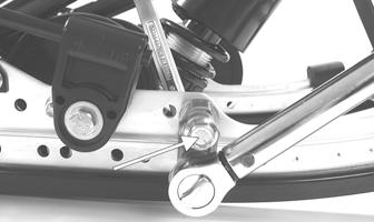
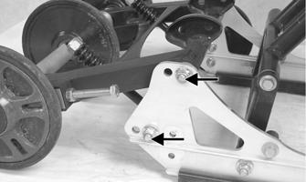
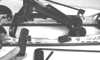
REMOVING 1.With skid frame removed and the rear springs removed from the adjusting cams, remove the lower cap screws and lock nuts securing the limiter straps to the rail support. Account for flat washers.
MS082A
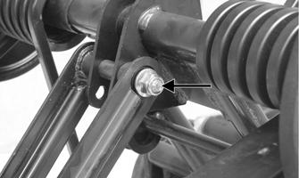
2.Remove the cap screw and lock nut securing the upper front shock absorber eyelet to the front arm.
Pull the shock eyelet free of the bracket. Account for a serrated axle.
SC024A
3.Remove the cap screw and lock nut securing the front arm to the slide rail; then remove the front arm and account for the serrated axles, bushings, and an axle tube.
SC025A
MS036A
4.Remove the cap screw and lock nut securing the shock bracket/inner idler wheels to the slide rail.
SC026A
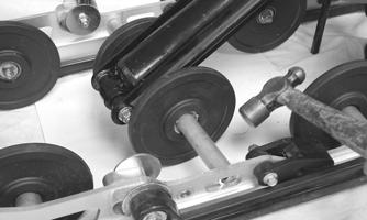
5.From one side, tap on the shaft of the assembly rearward until the shaft is clear of the slide rail; then remove the assembly.
SC027
6.Remove the outer spacers and idler wheels; then slide the axle out of the shock bracket.
7.Remove the cap screw and lock nut securing the shock absorber to the bracket.
MS086A
INSPECTING 1.Inspect all front arm weldments for cracks or unusual bends.
2.Closely inspect all tubing for cracks or unusual bends.
3.Inspect the bearings, bushings, and front arm spacers for wear or damage. 4.Inspect the shock absorber for damage and for any signs of oil leakage especially at the point where the shock shaft enters the shock body.
5.Inspect the shock absorber eyelet welds (at each end) for any cracks, signs of separation, or for unthreading. INSTALLING 1.Secure the shock absorber to the shock bracket with the cap screw and lock nut. Tighten securely.
MS086A
NOTE: Do not over-tighten the shock absorber cap
screw as the shock eyelet must be free to pivot.
2.Apply grease to the axle and install it into the shock bracket; then install the idler wheels and outer spacers.
SC027
3.Place the idler wheel/shock bracket assembly into position on the skid frame making sure the axle is aligned with the hole in the slide rail. Secure with the cap screw and a new lock nut. Tighten only until snug.
SC026A
4.Position the front arm into the slide rail. Secure with cap screws and lock nuts. Tighten to 40 ft-lb.
SC029
NOTE: At this point, tighten the lock nut (from step
3) to 40 ft-lb.
SC030
5.Secure the upper shock eyelet and serrated axle in the mounting hole of the front arm. Secure with a cap screw and lock nut. Tighten to 40 ft-lb.
SC024A
6.Secure the limiter straps to the rail supports with cap screws, washers, and lock nuts. Tighten to 72 in.-lb.
Rear Upper Idler Wheels/Rear Springs
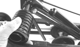
REMOVING 1.With the skid frame removed using the Rear Suspension Spring Tool, remove the spring from the adjusting cam.
! WARNING
Care must be taken when removing the spring or damage or injury could result.
MS063
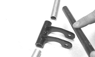
2.Mark the offset arm and the idler arm for assembly purposes. Note the flared side of the upper bushing is oriented outward.
SC014B
3.Loosen the cap screws securing the offset arm to the idler arm; then remove the offset arm assembly.
Account for two offset arm spacers. NOTE: Unless the offset arm is being replaced, the
cap screws and lock nuts do not need to be removed to remove the offset arm.

MS064
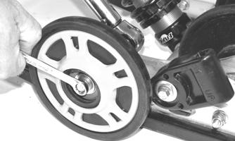
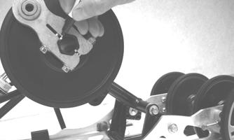
4.Using the appropriate Idler Wheel Puller Kit, remove the wheel.
SC015
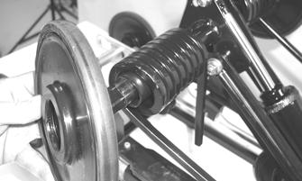
5.Remove the cap screw, lock nut, and three flat washers securing the spring slide to the rail. Account for a slide block and washer.
SC016A
MS068
6.Remove the spring and sleeve from the idler arm.
MS069
NOTE: Use the same procedure for the other side. CLEANING AND INSPECTING 1.Clean the bearing with a clean cloth. 2.Inspect each idler wheel and plastic hub for cracks or damage. 3.Rotate the idler wheel bearings (by hand) and inspect for binding or roughness. 4.If a bearing must be replaced, see Idler
Wheels/Mounting Blocks - Cleaning and Inspecting in this sub-section.
NOTE: If the idler wheel has no snap ring securing
the bearing, the idler wheel is not serviceable.
5.Inspect the spring, spring slide, sleeve, washers, slide block insert, and shaft area for wear. 6.Inspect the adjusting cams and arms for cracks. INSTALLING 1.Slide the sleeve and spring onto the idler arm.
MS069
2.Place the slide spacer and slide block (with spring in slide block) into position on the slide rail. Secure with a cap screw, three flat washers, and lock nut.
Tighten to 20 ft-lb.
MS068
NOTE: Make sure the spring is located above the
spring slide mounting cap screw.
SC017
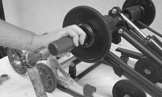
3.Using the appropriate wheel insertion tool (from
Idler Wheel Puller Kit), install the rear upper idler wheel on the idler arm.
SC018
CAUTION
When driving the idler wheel onto the idler arm, use a tool to contact the inside race of the bearing or damage to the wheel or bearing may occur.
4.Install the two offset arm spacers onto the idler arm.
MS064
5.Install the axle with a thin flat washer through the back side of the flared bushing of the offset arm. NOTE: If the flared bushing in the offset arm is
loose, it must be cleaned and green Loctite #609 must be applied to it prior to installation.
6.Align the marks on the idler arm to the centerline of the offset arm assembly; then install the offset arm with the flared side of the bushing out. Secure the offset arm to the idler arm with cap screws and lock nuts. Tighten to 20 ft-lb.
SC014A
NOTE: When tightening the offset arm lock nuts,
tighten the upper lock nut first to ensure an even clamp load.
Idler Arm/Rear Arm
DISASSEMBLING 1.With the skid frame removed, remove the rear upper idler wheels and springs (see Rear Upper Idler
Wheels/Rear Springs in this sub-section).
MS074
2.Remove the cap screw and lock nut securing the upper shock eyelet to the idler arm. Account for a spacer, lock nut, and bushings.
SC019A
AG553D
NOTE: Mark the hole that the upper shock links
are mounted in for assembling purposes.
MS076
3.Remove the cap screw and lock nut securing the upper shock links to the idler arm. Account for a lock nut, spacer, and axle links.
SC020A
MS031
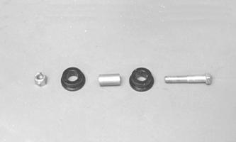
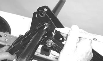
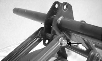
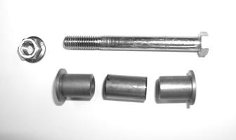
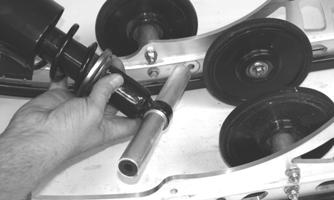
4.Remove the cap screw, washer, and lock nut securing the rear arm to the slide rail. Account for the serrated axles and axle tube.
MS028
5.Remove the cap screw and lock nut securing the rear arm to the idler arm. Account for the aluminum axle and bushing assemblies.
SC022A
CLEANING AND INSPECTING 1.Closely inspect the rear arm/idler arm tubing and brackets for cracks or unusual bends.
2.Clean the bearings with a clean cloth. 3.Inspect each idler wheel for cracks or damage. 4.Inspect the bushings (located in the arm pivot area) for wear or damage. 5.Inspect all welds and the tubing of the upper arm for cracks or unusual bends.
6.Inspect the two adjusting cams for damage. 7.If an idler wheel bearing must be replaced, see Idler
Wheels/Mounting Blocks - Cleaning and Inspecting in this sub-section.
ASSEMBLING 1.Install the rear arm onto the idler arm with an aluminum axle, bushing assemblies, and two cap screws (coated with blue Loctite #243). Tighten only until snug.
SC022A
2.Place the rear arm assembly into position. Secure with a cap screw, washer, and lock nut. Tighten to 40 ft-lb.
SC021A
3.Place a support beneath the rear arm; then tighten the cap screws (from step 1) to 40 ft-lb.
MS080
4.Position the shock links in the appropriate holes of the idler arm brackets (as noted during disassembling).
Place a spacer between the center of the brackets. Insert the axle links into the upper shock link eyelets; then insert the cap screw through the eyelets. Secure with a cap screw, washer, and lock nut. Tighten securely.
MS031
SC023A
5.Place the upper shock eyelet with bushings between the idler arm brackets making sure the spacer is properly positioned between the brackets. Secure with a cap screw and lock nut. Tighten securely.
SC019A
NOTE: Do not over-tighten the shock absorber cap
screw as the shock eyelet must be free to pivot.
6.Grease the idler arm and rear arm grease fittings with low-temperature grease. 7.Install the rear upper idler wheels and rear springs (see Rear Upper Idler Wheels/Rear Springs in this sub-section).
Rear Shock Absorber/Links and Pivot Assembly
NOTE: Before removing the skid frame by using the
Rear Suspension Spring Tool, remove the spring from the adjusting cam.
! WARNING
Care must be taken when removing the spring from the adjusting cam or damage or injury could result.
DISASSEMBLING NOTE: When removing center components from
the skid frame, loosening all axle cap screws/lock nuts will make removing easier.
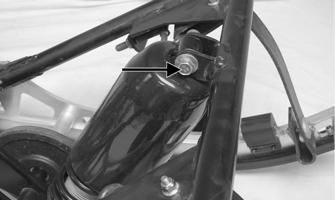
1.With the skid frame removed, remove the cap screw and lock nut securing the shock absorber to the eyelet of the idler arm and remove the shock absorber.
Account for a sleeve, cap screw, lock nut, and bushings.
MS089A
MS091
NOTE: For ease of servicing the rear arm compo-
nents, engage the overload springs.
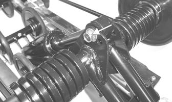
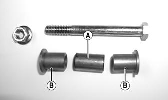
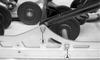
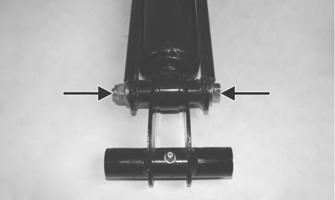
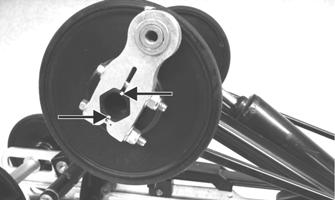
2.Mark the hole that the shock links are mounted on the idler arm for assembly purposes; then remove the cap screw and lock nut securing the shock links to the idler arm bracket. Account for the two axles (B) and spacer (A).
MS031A
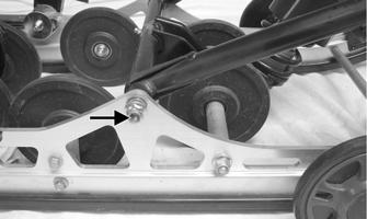
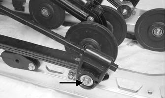
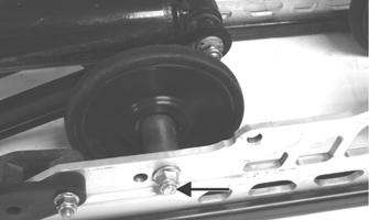
3.Note the hole location that the idler wheel/pivot assembly is in; then remove the cap screw and lock nut securing the assembly to the rails.
SC032
4.Tap the idler wheel/pivot assembly forward and up until it clears the slide rails; then lift the assembly upward and out from between the rails.
MS095
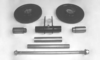
5.With the idler wheel/pivot assembly removed, remove the two outer spacers, an axle, and center spacer from the pivot bracket.
SC035B
6.Remove the cap screw, lock nut, and washer securing the shock rod links to the offset arm. Account for all components and mounting hardware.
SC036
CLEANING AND INSPECTING 1.Clean shock pivot and idler wheel axle in part-cleaning solvent. Dry with compressed air.
! WARNING
Always wear an approved pair of safety glasses when using compressed air.
2.Clean the idler wheel bearings with a clean cloth. 3.Closely inspect the pivot bracket arm and axle for cracks, wear, bends, or elongated holes. 4.Inspect the idler wheels for signs of cracking, wear, or outer rubber separation from plastic wheel. 5.Rotate the idler wheel bearings (by hand) and inspect for any signs of binding or roughness. 6.If the idler wheel bearing must be replaced, see Idler
Wheels/Mounting Blocks - Cleaning and Inspecting in this sub-section.
7.Inspect the shock absorber for any signs of oil leakage especially at the point where the shock shaft enters the shock body. 8.Inspect the rubber shock bushings located in the shock absorber eyelets for cracks or deterioration. 9.Inspect the shock absorber eyelet welds (at each end) for any cracks or signs of separation. 10.Inspect the welds securing the eyelets of the shock links for cracks or signs of separation. If either condition exists, replace the shock link. 11.Inspect the axle surfaces for any signs of corrosion.
If corrosion is found, lightly buff the surface of the axle with #400 wet-or-dry sandpaper; then apply a light coat of grease. ASSEMBLING 1.Secure the shock rod links (with axles) and the lower end of the shock absorber to the idler wheel/pivot assembly with the cap screw and lock nut. Tighten to 40 ft-lb.
MS096A
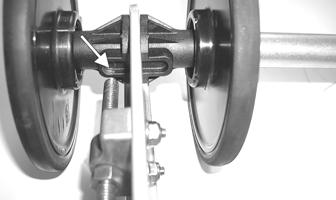
2.Apply a thin coat of low-temperature grease to the axle and slide the axle and center spacer into the shock pivot bracket. Have equal amounts of the axle exposed on either side of the pivot bracket tube.
FC189
3.From each side of the pivot, install an idler wheel and spacer. 4.Lower the idler wheel/pivot assembly down between the rails. Align the axle with the mounting hole (as noted during disassembling). Secure with the cap screw and a new lock nut. Tighten to 40 ft-lb.
SC033
SC032
5.Position the shock links in the appropriate holes of the idler arm brackets (as marked during disassembling). Place a spacer between the center of the brackets; then insert the link axles into the upper shock link eyelets. Secure with a cap screw, washer, and lock nut. Tighten securely.
SC031A
6.Secure the shock absorber to the idler arm with bushings, sleeve, lock nut, and a cap screw. Tighten to 40 ft-lb.
MS100
Slide Rails
REMOVING NOTE: When replacing one or both slide rails is
necessary, remove one slide rail at a time. The remaining slide rail will then hold the rail supports, axles, and brackets in their correct assembly order. Always mark the mounting hole locations during disassembly to speed up the assembly process and to prevent any damage.
1.With the skid frame removed and the rear arm springs disengaged, remove the end cap from the slide rail. Account for a cap screw and lock nut.
MS016A
2.Remove the machine screw and lock nut securing the wear strip to the front of the slide rail. 3.Using a suitable driving tool, drive the wear strip off the rail.
4.Remove the cap screws and lock nuts securing the front arm limiter straps to the rail support. 5.Remove the cap screws securing the rail supports to the slide rail.
6.On the slide rail being replaced, remove the cap screws and lock nuts securing the inner and outer idler wheels and the idler wheel mounting blocks.
Account for flat washers.
MS103A
MS104A
7.Remove the lock nuts and cap screws securing the articulating skid frame to the mounting location of the slide rails.
SC037A
NOTE: The rear idler wheel from the opposite side
may need to be removed to remove the cap screws securing the articulating skid frame being removed.
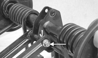
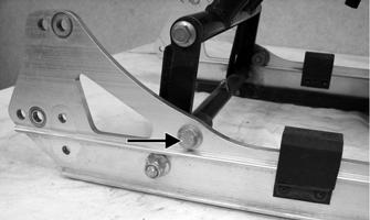
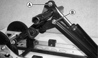
8.Remove the cap screw and lock nut (A) securing the shock bracket/wheel assembly to the slide rail; then remove the lock nut and cap screw (B) securing the front arm to the slide rails.
SC039A
NOTE: If removing the cap screw is necessary to
replace the slide rail, install the cap screw from the opposite side into the assembly to secure the components and aid in replacing the slide rail.
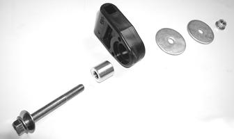
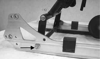
9.Remove the cap screw and flat washer securing the spring slide and overload spring to the rail. Account for a spacer, the slide block, overload spring, retainer clips, bushing, one small washer, and two large washers.
SC040A
MS108
10.Remove the cap screw and lock nut securing the overload spring tension block to the slide rail.
SC041A
11.Remove the cap screws from the rear arm limiter.
SC042A
12.Remove the cap screw and lock nut securing the rear arm to the rail.
SC043A
NOTE: At this point, the slide rail should be free of
the skid frame components and can be removed.
NOTE: If the shock pad must be replaced, see
Shock Pads at the beginning of this procedure.
INSPECTING 1.Inspect the slide rail for cracks, elongated holes, or unusual bends.
2.Inspect the wear strip for wear. The wear strip must be 0.42in. thick or thicker. If the wear strip measurement is less than specified, replacement of both wear strips is necessary. INSTALLING 1.Place the slide rail into position; then install the cap screws and new lock nuts securing the components to the slide rails in the following order and tighten them to 40 ft-lb.
A.Rear Arm Shock Pivot Axle
B.Front Arm Shock Bracket Axle
C.Front Arm
D.Rear Arm
SC044A
SC043B
NOTE: Take care that all the shim washers and
spacers are in place on the center components of the slide rail.
2.Install the rear arm limiter and secure with cap screw (coated with blue Loctite #243) and tighten to 40 ft-lb.
SC042A
3.Secure the two front rail supports with cap screws.
Tighten to 20 ft-lb.
SC047A
4.Secure the limiter straps to the front rail support with cap screws, washers, and lock nuts and tighten to 72 in.-lb.
5.Place the overload spring with retaining clips and bushing to the proper hole in the slide rail.
MS119A
6.Place the spring into the spring slide; then with the overload spring in position, place the spring slide and slide block assembly into position on the slide rail. Secure with a cap screw, washer, spacer, two large flat washers, and a lock nut. Tighten to 20 ft-lb.
SC046A
7.Install the overload spring tension block with a cap screw and lock nut. Tighten securely.
SC041A
8.Secure the outer idler wheel mounting block with the cap screw and lock nut. Tighten to 20 ft-lb. NOTE: When tightening the mounting block lock
nut, install the idler wheel cap screw (A) to maintain proper alignment.
MS121A
9.Secure the outer idler wheel to the mounting block with a cap screw, flat washers, idler wheel, and a lock nut. Tighten to 20 ft-lb.
MS122
10.Secure the end cap onto the slide rail using a cap screw and lock nut. Tighten to 80 in.-lb.
MS016A
NOTE: Use a file to remove any sharp edges on the
lower portion of the rail.
11.From the back, start the wear strip onto the rail; then using a soft hammer, drive the wear strip forward into position. Secure with a machine screw and lock nut. Tighten to 50 in.-lb.
MS289
MS016B
12.Install the articulating skid frame to the slide rails; then secure with two cap screws and lock nuts.
Tighten to 20 ft-lb.
SC037A
NOTE: If the rear idler wheel was removed from
the opposite side slide rail, install the idler wheel and secure it to the mounting block with cap screw, washer, and lock nut. Tighten to 20 ft-lb.
SC038A
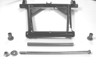
Articulating Skid Frame
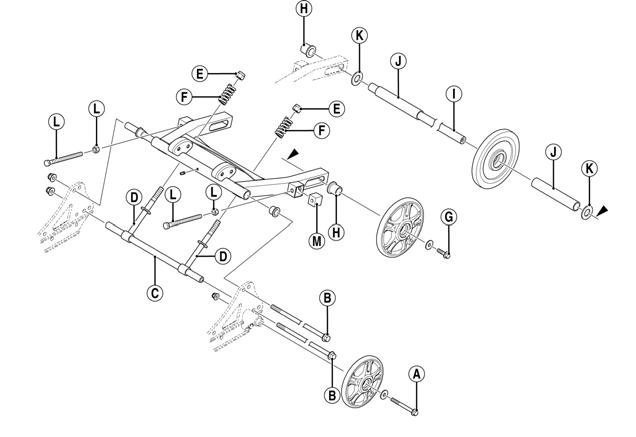
NOTE: For the following procedure, refer to illus-
tration 744-166A.
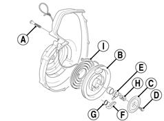
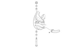
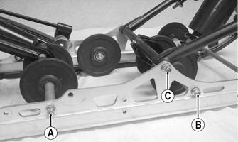
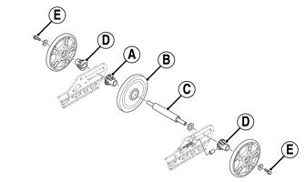
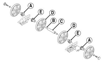
DISASSEMBLING 1.Remove the rear idler wheel cap screw (A), washer, and lock nut from the cap screw side of the skid frame. 2.Remove the two cap screws (B) and lock nuts securing the articulating skid frame to the slide rail. 3.With the adjuster rod axle (C) in place in the adjuster rods (D), remove the lock nuts (E) from the adjuster springs (F); then remove the adjuster rods and axle from the swing arm. 4.Remove the two cap screws (G) securing the rear axle/idler wheel assembly to the swing arm; then remove the idler wheels and account for the two adjuster bushings (H). 5.From one side, slide the rear axle (I) out from between the swing arm and account for the two idler wheel spacers (J) and two washers (K). 6.Remove the two cap screws and lock nuts (L) securing the adjuster blocks (M) to the swing arm.
INSPECTING 1.Inspect each idler wheel and plastic hub for cracks or damage. 2.Rotate the idler wheel bearings (by hand) and inspect for binding or roughness. 3.Inspect all bushings for wear or damage. 4.Inspect all weldments and the tubing of the arms and spacers for cracks or unusual bends. 5.Inspect the track bumper guides for wear. 6.Inspect the axle surfaces for any signs of corrosion. If corrosion is found, lightly buff the surface of the axle with #400 wet-or-dry sandpaper; then apply a light coat of grease. ASSEMBLING 1.Install the adjuster blocks (M) into the swing arm; then thread the two cap screws with lock nuts (L) into the blocks.
2.Slide the rear axle through one side of the swing arm and through a washer (K) and an idler wheel spacer (J); then in order on the rear axle (I), install the center idler wheel, the remaining spacer (J), and washer (K). Continue to slide the rear axle through the other side of the swing arm.
3.Slide an adjuster bushing (H) on each end of the rear axle making sure the bushings are properly positioned to the adjuster bolts; then secure each rear axle idler wheel with a cap screw (G). Tighten only until snug. 4.Install the adjuster rods (D) into the swing arm; then install the adjuster springs (F) and lock nuts (E). Tighten only until snug. 5.Slide the adjuster rod axle (C) into the adjuster rods; then install the swing arm axle into the swing arm. 6.Position the articulating skid frame between the slide rails; then with the adjuster rod axle (C) and the swing arm axle centered to the mounting holes of the slide rails, install the cap screws (B) securing the articulating skid frame to the slide rails.
7.Install new lock nuts to the cap screws (B) and tighten to 20 ft-lb.
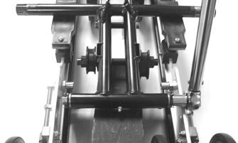
8.Install the rear idler wheel to the mounting block of the slide rail. Secure with cap screw (A), flat washer, and lock nut. Tighten to 20 ft-lb. ADJUSTING 1.Place the skid frame assembly on a flat work surface. 2.Preload the articulating suspension by equally adjusting the lock nuts on the spring brackets until both rear idler wheels are 1 in. off the work surface.
744-166A
! WARNING
The spring brackets must be adjusted equally. Improper adjustment of the spring brackets may result in binding in the articulating suspension. Upon completing the adjustment, there must be at least two full threads behind the lock nuts.
Installing Skid Frame
1.Using an appropriate handlebar/steering post support stand, tip the snowmobile onto one side. 2.Pull the track away from the tunnel and spread open; then place the skid frame into the track. 3.Position the front of the skid frame into the tunnel and align the front arm with the appropriate mounting hole in the tunnel. Insert the cap screw with washers through the tunnel mounting hole and through the front arm. DO
NOT TIGHTEN AT THIS TIME. Repeat this procedure on the other side.
CAUTION
When installing the skid frame, make sure the rear arm shock mounting location on the pivot/axle is positioned correctly above the axle or component damage will occur.
739-992A
NOTE: To aid in centering the front arm with the
hole in the tunnel, position the skid frame and track at a 45° angle to the bottom of the tunnel.
4.Install the rear of the skid frame and the track into position in the tunnel.
5.Align the rear arm assembly with the appropriate hole in the tunnel. Secure the rear arm assembly with a cap screw. TIGHTEN ONLY UNTIL SNUG.
6.Tip the snowmobile onto the other side; then align the rear arm assembly with the appropriate hole in the tunnel. Secure the offset arm assembly with a cap screw, lock washer, and flat washer. TIGHTEN ONLY UNTIL
SNUG.
NOTE: Do not install the short legs of the rear
springs onto the adjusting cams at this time.
7.At this time, place the snowmobile to the upright position; then tighten both rear arm mounting cap screws to 40 ft-lb.
NOTE: At this point, tighten all remaining skid
frame mounting hardware to 40 ft-lb.
8.Using the Rear Suspension Spring Tool, install the short legs of the rear springs onto the adjusting cams making sure the cams are in the same adjustment positions. 9.Adjust track tension and alignment (see Track Tension and Track Alignment in Drive Train/Track/Brake Systems section).
Servicing Suspension (Lynx 2000 LT)
This sub-section has been organized so each procedure can be completed individually and efficiently. NOTE: Some components may vary from model to
model. The technician should use discretion and sound judgment when removing and installing components.
Removing Skid Frame
NOTE: Many service procedures can be performed
without removing the skid frame. The technician should use discretion and sound judgment when removing and installing components.
1.Unload the tension springs from the adjuster blocks. 2.To avoid having the adjuster bushings bind during loosening of the track, remove the rear idler wheel caps and loosen the cap screws on the rear axle.
0742-921
3.Loosen the jam nuts and two track-tension adjusting bolts. 4.Place a support stand under the rear bumper; then while holding the flared bushing, remove the rear arm mounting cap screws securing the skid frame to the tunnel. Account for lock washers and flat washers.
NOTE: The support stand should hold the snowmo-
bile level but not raised off the floor.
5.Remove the support stand; then using an appropriate handlebar/steering post support stand, tip the snowmobile onto one side. 6.Slide the skid frame rearward far enough to drop the front arm out of the slider axle; then remove the skid frame.
End Caps
REMOVING 1.Remove the lock nut and cap screw securing the end cap.
FZ026A
2.Using a hammer, tap the end cap off the rail. CLEANING AND INSPECTING 1.Inspect the end cap area of the slide rail for cracks and wear. 2.Inspect the end cap for any signs of cracking or wear. 3.Clean both the slide rail area and the end cap. Using compressed air, clean the areas of dirt and gravel.
4.Inspect the cap screw for cracked, stretched, or damaged threads. Use a new lock nut when assembling. INSTALLING 1.Position the end cap on the slide rail; then align the hole in the end cap with the hole in the slide rail. 2.Secure with a cap screw and lock nut. Tighten to 80 in.-lb. ! WARNING
Always wear an approved pair of safety glasses when using compressed air.
Wear Strips
REMOVING 1.Remove the machine screw and lock nut securing the wear strip to the front of the slide rail.
CM222A
2.Align the wear strip with the openings (windows) in the track; then using a suitable driving tool, drive the wear strip rearward off the slide rail.
739-884A
CLEANING AND INSPECTING 1.Clean the slide rail using parts-cleaning solvent and compressed air.
! WARNING
Always wear an approved pair of safety glasses when using compressed air.
2.Inspect the slide rail for cracks. If any cracks are found, replace the slide rail. 3.Using a straightedge, inspect the slide rail for any unusual bends. With the slide rail removed, place the straightedge along the bottom surface of the slide rail. If the rail is found to be bent, it must be replaced. INSTALLING NOTE: Use a file to remove any sharp edges on the
lower portion of the rail.
1.Align the wear strip with the openings (windows) in the track and from the back, start the wear strip onto the rail; then using a block of wood and a hammer, drive the wear strip forward into position. 2.Secure with a machine screw and lock nut. Tighten to 50 in.-lb.
REMOVING 1.Using a 3/16-in. drill bit, drill out the rivets securing each front shock pad to the slide rail. Account for the retaining brackets. 2.Remove the Torx-head screws and lock nuts securing the rear shock pads to the slide rail; then remove the shock pads. INSPECTING 1.Inspect the pad and retaining brackets for damage or wear. 2.Inspect the rivet holes in the slide rail for damage or elongation. INSTALLING 1.Place the front pads and retaining brackets into position on the slide rail; then secure with rivets. 2.Place the rear pads into position on the slide rails; then secure with the Torx-head screws and lock nuts.
Tighten securely.
Idler Wheels/Mounting Blocks
REMOVING 1.Remove the cap screw and lock nut securing the idler wheel to the idler wheel mounting block; then remove the cap screw and lock nut securing the mounting block to the slide rail.
MS003A
2.Account for a flat washer from the idler wheel cap screw. CLEANING AND INSPECTING 1.Clean the bearing with a clean cloth. 2.Inspect each idler wheel for cracks or damage. 3.Rotate the idler wheel bearing (by hand) and inspect for binding or roughness. 4.If a bearing must be replaced, use this procedure.
A.Remove the bearing snap ring. B.Using a hydraulic press or suitable driving tool, remove the bearing from the inside of the wheel. C.Press the new bearing (on its outer race) into the idler wheel.
MS006A
D.Install the snap ring making sure the “sharp side” is directed away from the bearing.
MS007A
INSTALLING 1.Secure the mounting block on the slide rail with a cap screw and lock nut. Tighten to 20 ft-lb. NOTE: For proper alignment, install an idler wheel
cap screw into the top mounting block hole prior to tightening.
TZ025
2.Place the idler wheel to the mounting block; then secure the idler wheel assembly with a cap screw, flat washer, and a lock nut. Tighten to 20 ft-lb.
TZ026
Front Arm Assembly
REMOVING 1.With the skid frame removed and the rear springs removed from the adjusting cams, remove the cap screws and lock nuts securing the limiter straps to the front arm. Account for flat washers.
TZ027A
2.Remove the cap screw and lock nut securing the upper front shock absorber eyelet to the front arm.
Pull the shock eyelet free of the bracket. Account for a sleeve.
ZJ271A
3.Remove the cap screw and lock nut securing the front arm to the slide rail. Account for the external tooth lock washer.
TZ028A
4.Remove the front arm and account for the front arm axle. 5.Remove the front outer idler wheel and mounting block from the side of the slide rail in which the front arm shock axle cap screw was installed. 6.Remove the cap screws, washer, and lock nut from the front shock axle; then from the side that the idler wheel and mounting block was removed, tap the assembly forward far enough for the axle assembly to clear the slide rails. Account for an axle, two spacers, and two shim washers.
TZ029
TZ030
INSPECTING 1.Inspect all front arm weldments for cracks or unusual bends; then inspect the front arm mounting brackets for cracks and for elongated holes. 2.Closely inspect all tubing for cracks or unusual bends. 3.Inspect the bearings, bushings, and front arm spacers for wear or damage.
4.Inspect the shock absorber for damage and for any signs of oil leakage especially at the point where the shock shaft enters the shock body. 5.Inspect the shock absorber eyelet welds (at each end) for any cracks, signs of separation, or for unthreading. INSTALLING 1.With the rubber bushing in place, install the axle into the lower shock eyelet bushing assembly; then install the two shim washers and two spacers. NOTE: Applying a light film of lubricant to the rub-
ber bushing will aid in installing.
2.Position the front arm shock axle assembly on the skid frame making sure the spacers and washers are properly positioned. Secure with the cap screw, washer, and a new lock nut. Tighten to 40 ft-lb.
TZ031
3.On the side that the idler wheel and mounting block were removed from, secure the mounting block to the slide rail with a cap screw and lock nut. Tighten to 20 ft-lb.
NOTE: For proper alignment, install an idler wheel
cap screw and lock nut into the top mounting block hole prior to tightening.
TZ025
4.Secure the idler wheel to the mounting block with a cap screw and a lock nut. Tighten cap screw to 20 ft-lb.
TZ026
5.Install the axle into the front arm; then position the front arm to the mounting location of the slide rail.
Secure with cap screws, external tooth washer, and lock nuts. Tighten to 40 ft-lb.
TZ028A
6.Secure the upper shock eyelet and axle in the mounting hole of the front arm. Secure with a cap screw and lock nut. Tighten securely.
ZJ271A
NOTE: Do not over-tighten the shock absorber cap
screw as the shock eyelet must be free to pivot.
7.Secure the limiter straps to the front arm with cap screws, washers, and lock nuts. Tighten to 120 in.-lb.
TZ027A
Rear Arm/Rear Shock Pivot Assembly
REMOVING 1.With the skid frame removed using the Rear Suspension Spring Tool, remove the spring from the adjusting cam.
! WARNING
Care must be taken when removing the spring or damage or injury could result.
TZ002A
2.Mark the offset arm and the idler arm for assembly purposes.
TZ003
3.Loosen the cap screws and lock nuts securing the offset arm assembly to the idler arm; then remove the offset arm assembly. Account for a flanged axle, idler spacer, and washer.
TZ004A
FZ036
4.Remove the idler wheel using Idler Wheel Puller Kit.
TZ005
5. Remove the cap screw, flat washers, and lock nut securing the spring slide and overload spring to the slide rail. Account for the spring slide and all mounting hardware.
TZ007A
NOTE: If the overload spring is being removed, use
a punch to drive the bushing out from the back side of the slide rail and remove the spring.
TZ006A
TZ008
6.Remove the spring and sleeve from the idler arm.
TZ009
NOTE: Use the same procedure for the other side. 7.Remove the cap screw (A) and lock nut securing the upper shock eyelet to the idler arm; then remove the cap screw (B) and lock nut securing the upper shock links to the idler arm. Account for the cap screws, lock nuts, and sleeves.
TZ010B
NOTE: For assembling purposes, note the mounting
location of the shock links to the idler arm.
8.Remove the cap screw and lock nut securing the rear shock pivot/idler wheel assembly to the slide rails; then remove the assembly and account for the axle, axle spacers, and shim washers (if applicable).
TZ012A
9.Remove the cap screw and lock nut securing the rear arm shock absorber and shock links to the rear shock pivot. Account for the cap screws, lock nuts, and sleeves.
TZ013A
TZ014
10.Remove the cap screws securing the idler arm to the rear arm. Account for the aluminum axle.
TZ015A
11.Remove the cap screw and lock nut securing the rear arm to the slide rail. Account for the bushings and axle tube.
TZ016A
CLEANING AND INSPECTING 1.Clean the bearings with a clean cloth. 2.Inspect each idler wheel for cracks or damage. 3.Inspect the bushings (located in the arm pivot area) for wear or damage. 4.Inspect all welds and the tubing of the rear arm/idler arm for cracks or unusual bends. 5.Inspect the two adjusting cams for damage. 6.Rotate the idler wheel bearings (by hand) and check for binding or roughness. 7.If a bearing must be replaced, see Idler
Wheels/Mounting Blocks — CLEANING AND
INSPECTING in this sub-section. INSTALLING 1.Place the rear arm assembly into position between the slide rails. Secure with a cap screw and lock nut.
Tighten to 40 ft-lb.
TZ016A
2.Install the rear arm onto the idler arm with an aluminum axle and two cap screws. Tighten to 40 ft-lb.
TZ015A
3.With the sleeves installed, install the shock absorber and links to the mounting hole of the rear shock pivot with cap screws and lock nuts. Tighten securely. NOTE: The shock absorber and links must be
secured to the rear shock pivot before installing to the slide rails.
TZ017A
4.Assemble the rear shock pivot idler wheel assembly with the axle (A), axle tube (B), axle spacers (C), and shim washers (if applicable).
TZ014A
5.Install the rear shock pivot/idler wheel assembly to the mounting location in the slide rails and secure with cap screws and lock nuts. Tighten to 20 ft-lb.
TZ019
6.With the sleeves installed, install the shock absorber to the mounting hole of the idler arm along with the cap screw and lock nut; then secure the shock absorber links and spacer to the upper mounting hole of the idler arm with cap screws and lock nuts.
Tighten securely.
TZ010B
NOTE: Do not over-tighten the shock absorber cap
screw as the shock eyelet must be free to pivot.
NOTE: Make sure the spacer is installed between
the brackets of the idler arm before securing the shock links.
7.Slide the sleeve and spring onto the idler arm.
TZ009
8.Place the spring slide and slide block (with spring in slide block) into position on the slide rail. Secure with a cap screw and washer. Tighten to 20 ft-lb.
TZ008
NOTE: Install the rear arm springs onto the
adjuster blocks after the skid frame has been installed.
TZ021
9.Using a suitable driving tool, install the rear upper idler wheel on the idler arm.
TZ022
CAUTION
When driving the idler wheel onto the idler arm, use a tool to contact the inside race of the bearing or damage to the wheel or bearing may occur.
MS072A
10.Install the idler spacer collar onto the idler arm.
TZ023
11.Install the axle with a thin flat washer through the back side of the flared bushing of the offset arm. NOTE: If the flared bushing in the offset arm is
loose, it must be cleaned and green Loctite #609 must be applied to it prior to installation.
12.Align the marks on the idler arm to the centerline of the offset arm assembly. Secure the offset arm to the idler arm with cap screws and lock nuts. Tighten to 20 ft-lb.
TZ004B
NOTE: When tightening the offset arm lock nuts,
tighten the lower lock nut first to ensure an even clamp load. Make sure the flared side of the bushing is directed outward.

TZ004C
13.Grease the idler arm and rear arm grease fittings with low-temperature grease.
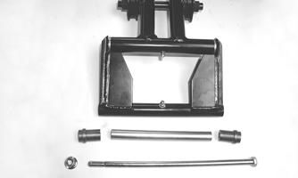
Rear Axle/Idler Wheels
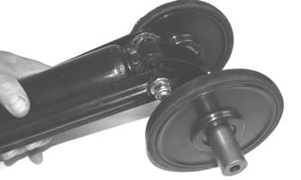
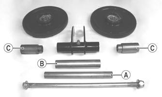
DISASSEMBLING REAR AXLE 1.With the skid frame removed, remove the cap screw and large flat washer securing the outer rear idler wheel. Remove the outer idler wheel from the shaft. 2.Loosen the track adjusting bolts. Slide the outer adjuster bushings off the axle. 3.Carefully slide the shaft out from the slide rails and inner idler wheels. Account for the rear idler wheel spacer and adjuster bushings. ASSEMBLING REAR AXLE 1.In order from the right-hand side, slide the axle through the slide rail axle slot; then place a bushing (A), inner idler wheel (B), and long spacer (C) with a flat washer on the axle. Slide the axle through the opposite slide rail axle slot.
742-937A
2.Place the plastic adjuster bushings (D) on the axle (on the outside of each axle slot); then install the outer idler wheels on the axle and secure with two cap screws (E) (coated with blue Loctite #243) and large flat washers. Tighten cap screws only until snug. NOTE: Care must be taken that the adjuster bush-
ing slot with the cap screw hole is aligned properly with the adjuster bolt.
MS058A
ZJ266
NOTE: Tighten the rear idler wheel axle only until
snug until the skid frame has been installed and track tension has been adjusted; then the axle assembly must be tightened to 20 ft-lb.
Installing Skid Frame
1.Using an appropriate handlebar/steering post support stand, tip the snowmobile onto one side. 2.Pull the track away from the tunnel and spread open; then place the skid frame into the track. 3.Position the front of the skid frame into the tunnel and engage the front arm with the slider axle in the tunnel.
0742-187
NOTE: To aid in centering the front arm with the
hole in the tunnel, position the skid frame and track at a 45° angle to the bottom of the tunnel.
4.Install the rear of the skid frame and the track into position in the tunnel. 5.Align the rear arm assembly with the appropriate hole in the tunnel. Secure the rear arm assembly with a cap screw. TIGHTEN ONLY UNTIL SNUG. 6.Tip the snowmobile onto the other side; then align the rear arm assembly with the appropriate hole in the tunnel. Secure the offset arm assembly with a cap screw, lock washer, and flat washer. TIGHTEN
ONLY UNTIL SNUG.
NOTE: Do not install the short legs of the rear
springs onto the adjusting cams at this time.
7.At this time, place the snowmobile in the upright position; then tighten both rear arm mounting cap screws to 40 ft-lb.
NOTE: At this point, tighten all remaining skid
frame mounting hardware to 40 ft-lb.
8.Using the Rear Suspension Spring Tool, install the short legs of the rear springs onto the adjusting cams making sure the cams are in the same adjustment positions. 9.Adjust track tension and alignment (see Track Tension/Track Alignment in Drivetrain/Track/Brake
Systems section).
CAUTION
After proper track tension and alignment have been attained, make certain that the rear axle cap screws are tightened to 20 ft-lb or component damage will occur.
Servicing Suspension (Lynx 2000)
This sub-section has been organized so each procedure can be completed individually and efficiently. NOTE: Some components may vary from model to
model. The technician should use discretion and sound judgment when removing and installing components.
Removing Skid Frame
NOTE: Many service procedures can be performed
without removing the skid frame. The technician should use discretion and sound judgment when removing and installing components.
1.To avoid having the adjuster bushings binding during loosening of the track, remove the rear idler wheel caps and loosen the cap screws on the rear axle.
0742-921
2.Loosen the jam nuts and two track-tension adjusting bolts. 3.Place a support stand under the rear bumper; then while holding the flared bushing, remove the rear arm mounting cap screws securing the skid frame to the tunnel.
NOTE: The support stand should hold the snowmo-
bile level but not raised off the floor.
4.Remove the support stand; then using a suitable handlebar support stand, tip the snowmobile onto one side. 5.Slide the skid frame rearward far enough to drop the front arm out of the slider axle; then remove the skid frame.
End Caps
REMOVING 1.Remove the lock nut and cap screw securing the end cap.
FZ026A
2.Using a hammer, tap the end cap off the rail. CLEANING AND INSPECTING 1.Inspect the end cap area of the slide rail for cracks and wear. 2.Inspect the end cap for any signs of cracking or wear. 3.Clean both the slide rail area and the end cap. Using compressed air, clean the areas of dirt and gravel.
4.Inspect the cap screw for cracked, stretched, or damaged threads. Use a new lock nut when assembling. INSTALLING 1.Position the end cap on the slide rail; then align the hole in the end cap with the hole in the slide rail. 2.Secure with a cap screw and lock nut. Tighten to 80 in.-lb. ! WARNING
Always wear an approved pair of safety glasses when using compressed air.
Wear Strips
REMOVING 1.Remove the machine screw and lock nut securing the wear strip to the front of the slide rail.
FZ026B
2.Align the wear strip with the openings (windows) in the track; then using a suitable driving tool, drive the wear strip rearward off the slide rail.
739-884A
CLEANING AND INSPECTING 1.Clean the slide rail using parts-cleaning solvent and compressed air.
! WARNING
Always wear an approved pair of safety glasses when using compressed air.
2.Inspect the slide rail for cracks. If any cracks are found, replace the slide rail. 3.Using a straightedge, inspect the slide rail for any unusual bends. With the slide rail removed, place the straightedge along the bottom surface of the slide rail. If the rail is found to be bent, it must be replaced. INSTALLING NOTE: Use a file to remove any sharp edges on the
lower portion of the rail.
1.Align the wear strip with the openings (windows) in the track and from the back, start the wear strip onto the rail; then using a block of wood and a hammer, drive the wear strip forward into position. 2.Secure with a machine screw and lock nut. Tighten to 50 in.-lb.
REMOVING 1.Using a 3/16-in. drill bit, drill out the rivets securing the front shock pads to the slide rail. Account for the retaining brackets. 2.Remove the rear shock pads. INSPECTING 1.Inspect the pads for damage or wear. 2.Inspect the rivet holes in the slide rail for damage or elongation. INSTALLING 1.Place the pads and retaining brackets into position on the slide rail. 2.Secure the pads with rivets.
Idler Wheels/Mounting Blocks
REMOVING 1.Remove the cap screw and lock nut securing the idler wheel to the idler wheel mounting block; then remove the cap screw and lock nut securing the mounting block to the slide rail.
FZ029A
FZ030A
2.Account for a flat washer from the idler wheel cap screw.
CLEANING AND INSPECTING 1.Clean the bearing with a clean cloth. 2.Inspect each idler wheel for cracks or damage. 3.Rotate the idler wheel bearing (by hand) and inspect for binding or roughness. 4.If a bearing must be replaced, use this procedure.
A.Remove the bearing snap ring.
B.Using a hydraulic press or suitable driving tool, remove the bearing from the inside of the wheel.
C.Press the new bearing (on its outer race) into the idler wheel.
MS006A
D.Install the snap ring making sure the “sharp side” is directed away from the bearing.
MS007A
INSTALLING 1.Secure the mounting block on the slide rail with a cap screw and lock nut. Tighten to 20 ft-lb. NOTE: For proper alignment, install an idler wheel
cap screw into the top mounting block hole prior to tightening.
FZ031A
2.Place the idler wheel to the mounting block; then secure the idler wheel assembly with a cap screw, flat washer, and a lock nut. Tighten to 20 ft-lb.
FZ032
Front Arm Assembly
REMOVING 1.With the skid frame removed and the rear springs removed from the adjusting cams, remove the cap screws and lock nuts securing the limiter straps to the front arm. Account for flat washers.
ZJ270A
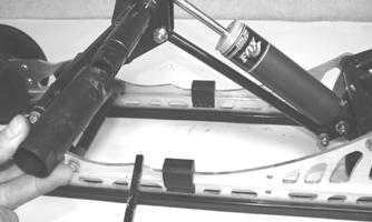
2.Remove the cap screw and lock nut securing the upper front shock absorber eyelet to the front arm.
Pull the shock eyelet free of the bracket. Account for a sleeve.
ZJ271A
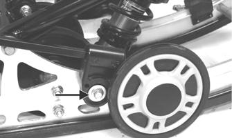
3.Remove the lock nut and cap screw securing the rear shock pivot to the front arm.
FZ049A
4.Remove the cap screw and lock nut securing the front arm to the front arm mounting bracket.
FZ050A
5.Remove the front arm and account for the front arm axle. 6.Remove the cap screw securing the front outer idler wheel to the idler wheel mounting block. Account for lock nut, cap screw, and flat washer.
FZ029A
7.Remove the cap screw and lock nut securing the idler wheel mounting block to the slide rail. NOTE: For ease of removal, remove the front outer
idler wheel and mounting block from the side of the slide rail in which the front arm shock axle cap screw was installed.
8.Remove the cap screws, washer, and lock nut from the front shock axle; then from one side, tap the assembly forward far enough for the axle assembly to clear the slide rails. Account for an axle, two spacers, and two shim washers.
FZ051A
FZ052
INSPECTING 1.Inspect all front arm weldments for cracks or unusual bends; then inspect the front arm mounting brackets for cracks and for elongated holes. 2.Closely inspect all tubing for cracks or unusual bends. 3.Inspect the bearings, bushings, and front arm spacers for wear or damage.
4.Inspect the shock absorber for damage and for any signs of oil leakage especially at the point where the shock shaft enters the shock body. 5.Inspect the shock absorber eyelet welds (at each end) for any cracks, signs of separation, or for unthreading. INSTALLING 1.With the rubber bushing in place, install the axle into the lower shock eyelet bushing assembly; then install the two shim washers and two spacers.
CM246A
2.Place the front arm shock axle assembly into position on the skid frame making sure the spacers and washers are properly positioned. Secure with the cap screw, washer, and a new lock nut. Tighten to 40 ft-lb.
FZ053
3.On the side that the idler wheel and mounting block were removed from, secure the mounting block on the slide rail with a cap screw and lock nut. Tighten to 20 ft-lb.
NOTE: For proper alignment, install an idler wheel
cap screw and lock nut into the top mounting block hole prior to tightening.
FZ055A
4.Secure the idler wheel to the mounting block with a cap screw and a lock nut. Tighten cap screw to 20 ft-lb.
FZ056
5.Install the axle into the front arm; then position the front arm to the mounting location of the slide rail. Secure with cap screws and lock nuts. Tighten to 40 ft-lb. NOTE: Move the rear arm assembly forward
enough to allow the rear arm springs to be installed into the slide blocks.
FZ054
6.Secure the rear shock pivot to the front arm with cap screw and lock nut. Tighten to 20 ft-lb.
FZ049
7.Secure the upper shock eyelet and axle in the mounting hole of the front arm. Secure with a cap screw and lock nut. Tighten securely.
ZJ271A
NOTE: Do not over-tighten the shock absorber cap
screw as the shock eyelet must be free to pivot.
8.Secure the limiter straps to the front arm with cap screws, washers, and lock nuts. Tighten to 72 in.-lb.
ZJ270
Rear Arm Assembly
REMOVING 1.With the skid frame removed using the Rear Suspension Spring Tool, remove the spring from the adjusting cam.
! WARNING
FZ033A
2.Mark the offset arm and the idler arm for assembly purposes.
FZ034
3.Loosen the cap screws and lock nuts securing the offset arm assembly to the idler arm; then remove the offset arm assembly. Account for a flanged axle, idler spacer, and washer.
FZ035A
FZ037
5. Remove the cap screw, flat washer, and lock nut securing the spring slide to the slide rail. Account for the spring slide and all mounting hardware.
FZ038A
MS014
6.Remove the spring and sleeve from the idler arm.
FZ039
NOTE: Use the same procedure for the other side. 7.Remove the cap screw (A) and lock nut securing the upper shock eyelet to the idler arm; then remove the cap screw (B) and lock nut securing the upper shock link to the idler arm. Account for the cap screws, lock nuts, and sleeves.
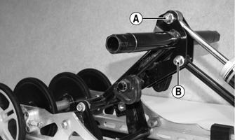
FZ040C
8.Remove the cap screw (A) and lock nut securing the rear arm shock absorber to the rear shock pivot; then remove the cap screw (B) and lock nut securing the shock absorber link to the pivot and account for the cap screws, lock nuts, and sleeves.
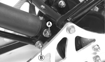
FZ041C
9.Remove the cap screw securing the rear arm to the idler arm. Account for the aluminum axle.
FZ085B
10.Remove the cap screw and lock nut securing the rear arm to the slide rail. Account for the serrated axles and axle tube.
FZ042A
CLEANING AND INSPECTING 1.Clean the bearings with a clean cloth. 2.Inspect each idler wheel for cracks or damage. 3.Inspect the bushings (located in the arm pivot area) for wear or damage. 4.Inspect all welds and the tubing of the rear arm/idler arm for cracks or unusual bends. 5.Inspect the two adjusting cams for damage. 6.Rotate the idler wheel bearings (by hand) and check for binding or roughness. 7.If a bearing must be replaced, see Idler
Wheels/Mounting Blocks — CLEANING AND
INSPECTING in this sub-section. INSTALLING 1.Place the rear arm assembly into position between the slide rails. Secure with a cap screw and lock nut.
Tighten to 40 ft-lb.
FZ043
2.Install the rear arm onto the idler arm with an aluminum axle and two cap screws. Tighten to 40 ft-lb.
FZ044
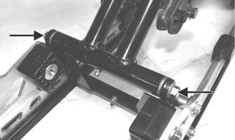
3.With the sleeves installed, install the shock absorber link to the lower mounting hole of the rear shock pivot; then install the shock absorber with cap screws (A) and (B) and lock nuts. Tighten securely.
FZ041C
CAUTION
When installing the shock absorber link, note that the offset of the link eyelets are directed away from the rear arm shock absorber for proper clearance.
0742-877
4.With the sleeves installed, install the shock absorber link to the lower mounting hole of the idler arm along with the cap screw (B) and lock nut; then secure the shock absorber to the idler arm with cap screws (A) and lock nuts. Tighten securely.
FZ040C
NOTE: Do not over-tighten the shock absorber cap
screw as the shock eyelet must be free to pivot.
NOTE: Install the rear arm springs onto the
adjuster blocks after the skid frame has been installed.
5.Slide the sleeve and spring onto the idler arm.
MS145
6.Place the spring slide and slide block (with spring in slide block) into position on the slide rail. Secure with a cap screw and washer. Tighten to 20 ft-lb.
FZ045
7.Using a suitable driving tool, install the rear upper idler wheel on the idler arm.
FZ046
CAUTION
When driving the idler wheel onto the idler arm, use a tool to contact the inside race of the bearing or damage to the wheel or bearing may occur.
MS014 MS072A
8.Install the idler spacer collar onto the idler arm.
9.Install the axle with a thin flat washer through the back side of the flared bushing of the offset arm. NOTE: If the flared bushing in the offset arm is
loose, it must be cleaned and green Loctite #609 must be applied to it prior to installation.
10.Align the marks on the idler arm to the centerline of the offset arm assembly. Secure the offset arm to the idler arm with cap screws and lock nuts. Tighten to 20 ft-lb.
FZ048A
NOTE: When tightening the offset arm lock nuts,
tighten the lower lock nut first to ensure an even clamp load. Make sure the flared side of the bushing is directed outward.
FZ048B
11.Grease the idler arm and rear arm grease fittings with low-temperature grease.
Rear Axle/Idler Wheels
DISASSEMBLING REAR AXLE 1.With the skid frame removed, remove the cap screw and large flat washer securing the outer rear idler wheel. Remove the outer idler wheel from the shaft. 2.Loosen the track adjusting bolts. Slide the outer adjuster bushings off the axle. 3.Carefully slide the shaft out from the slide rails and inner idler wheels. Account for the rear idler wheel spacer and adjuster bushings.
742-873A
1.In order from the right-hand side, slide the axle through the slide rail axle slot; then place a bushing (A), inner idler wheel (B), rear idler wheel spacer (C), inner idler wheel (D), and bushing (E) on the axle. Slide the axle through the opposite slide rail axle slot. 2.Place the plastic adjuster bushings on the axle (on the outside of each axle slot); then install the outer idler wheels on the axle and secure with two cap screws (coated with blue Loctite #243) and large flat washers. Tighten cap screws only until snug.
ZJ266
FC194
NOTE: Tighten the rear idler wheel axle only until
snug until the skid frame has been installed and track tension has been adjusted; then the axle assembly must be tightened to 20 ft-lb.
Installing Skid Frame
1.Using an appropriate handlebar/steering post support stand, tip the snowmobile onto one side. 2.Pull the track away from the tunnel and spread open; then place the skid frame into the track. 3.Position the front of the skid frame into the tunnel and engage the front arm with the slider axle in the tunnel.
0742-187
NOTE: To aid in centering the front arm with the
hole in the tunnel, position the skid frame and track at a 45° angle to the bottom of the tunnel.
4.Install the rear of the skid frame and the track into position in the tunnel. 5.Align the rear arm assembly with the appropriate hole in the tunnel. Secure the rear arm assembly with a cap screw, lock washer, and flat washer. AT THIS
TIME, TIGHTEN ONLY UNTIL SNUG. 6.Tip the snowmobile onto the other side; then align the offset arm assembly with the appropriate hole in the tunnel. Secure the rear arm assembly with a cap screw, lock washer, and flat washer. AT THIS TIME,
TIGHTEN ONLY UNTIL SNUG.
NOTE: Do not install the short legs of the rear
springs onto the adjusting cams at this time.
7.At this time, place the snowmobile in the upright position; then tighten both rear arm mounting cap screws to 40 ft-lb. 8.Using the Rear Suspension Spring Tool, install the short legs of the rear springs onto the adjusting cams making sure the cams are in the same adjustment positions. 9.Adjust track tension and track alignment (see Track
Tension/Track Alignment in Drivetrain/Track/Brake
Systems section).
CAUTION