Drive System/Brake System GENERAL INFORMATION
The die-cast aluminum housings have been assembled with thread-rolling screws (trilobular). When assembling with these screws, start the screws carefully into the housing; then use the following torque values. Size
New Housing 8-9.5 ft-lb M8 (Torx T-40 Recess) 25-31 ft-lb M10 (Torx T-50 Recess) 37-45.5 ft-lb M6 (Torx T-30 Recess)
Reassembled Housing 6.5-9 ft-lb 21-25 ft-lb 31-38 ft-lb
SPECIAL TOOLS
A number of special tools must be available to the technician when performing service procedures in this section.
ATV0082A
3. Remove the front wheels. 4. Pump up the hand brake; then engage the brake lever lock. 5. Remove and discard the cotter pin securing the hex nut; then remove the hex nut and washer.
NOTE: When indicated for use, each special tool
will be identified by its specific name, as shown in the chart below, and capitalized. Description Backlash Measuring Tool (24-Spline Axle)
p/n 0544-010
Backlash Measuring Tool (27-Spline Axle)
0544-011
CV Boot Clamp Tool
0444-120
Hub Retaining Wrench
0444-270
Internal Hex Socket
0444-104
Pinion Gear/Shaft Removal Tool
0444-127
Gear Case Seal Installer Tool
0444-273
NOTE: Special tools are available from the Service Department.
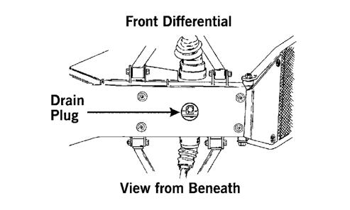
Front Differential
KX041
6. Release the brake lever lock. NOTE: It is not necessary to remove the brake hoses from the calipers for this procedure.
7. Remove the two brake calipers. Account for the four cap screws.
REMOVING DIFFERENTIAL
1. Secure the ATV on a support stand to elevate the wheels.
! WARNING Make sure the ATV is solidly supported on the support stand to avoid injury.
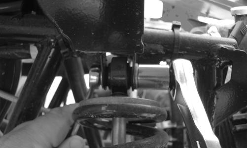
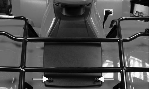
2. Remove the drain plug and drain the gear lubricant into a drain pan; then reinstall the plug and tighten to 45 in.-lb.
XR263A
NOTE: Do not allow the brake calipers to hang from their cable/hose.
8. Remove the tie rod cotter pins and discard the pins.
108