35 minute read
Drive System

GENERAL INFORMATION Gear cases are 4.0:1 ratio (500 or 3.6:1 ratio (700). The die-cast aluminum housings have been assembled with thread-rolling screws (trilobular). When assembling with these screws, start the screws carefully into the housing; then use the following torque values.
Size New Housing Reassembled Housing
M6 (Torx T-30 Recess) 9 ft-lb 8 ft-lb M8 (Torx T-40 Recess) 28 ft-lb 23 ft-lb
Description p/n
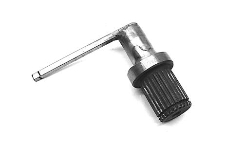
Backlash Measuring Tool (24-Spline Axle) 0544-010 Backlash Measuring Tool (27-Spline Axle) 0544-011 CV Boot Clamp Tool 0444-120 Internal Hex Socket 0444-104 Pinion Gear/Shaft Removal Tool 0444-127 Gear Case Seal Installer Tool 0444-273 Hub Retaining Wrench 0444-270 U-Joint Separator Tool 0444-128
NOTE: Never reuse a lock nut. Once a lock nut has
been removed, it must be replaced with a new lock nut.
SPECIAL TOOLS A number of special tools must be available to the technician when performing service procedures in this section. Refer to the current Special Tools Catalog for the appropriate tool description. NOTE: When indicated for use, each special tool
will be identified by its specific name, as shown in the chart below, and capitalized.
NOTE: Special tools are available from the Arctic
Cat Service Department.
Front Drive Actuator
NOTE: The actuator is not a serviceable compo-
nent. If it is defective, it must be replaced.
NOTE: The actuator will operate only when the
ignition switch is in the ON position.
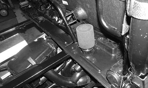
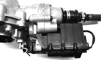
The front drive actuator is located on the left side of the front differential input housing. With the engine stopped and the ignition switch in the ON position, a momentary “whirring” sound can be heard each time the drive select switch is shifted. If no sound is heard, see Electrical System. If the actuator runs constantly or makes squealing or grinding sounds, the actuator must be replaced. REMOVING 1.Select LOCK on the drive select switch; then disconnect the connector on the actuator harness. Remove the front six cap screws securing the skid plate to the frame.
WC938A
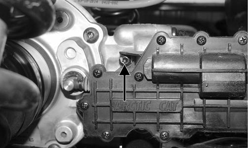
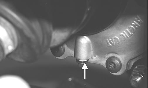
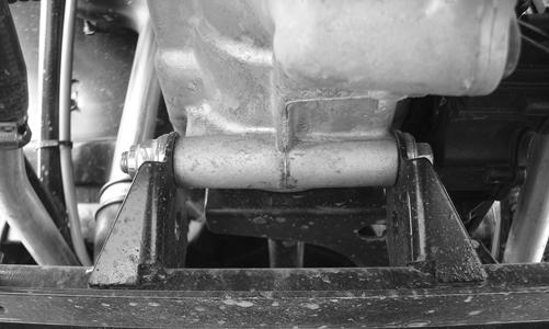
3.Remove the mounting cap screw from below the actuator on the suspension side.
WC940A
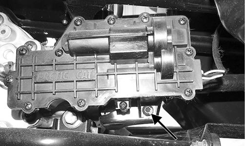
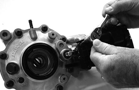
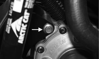
4.Loosen but do not remove the mounting cap screw at the front of the actuator; then slide the actuator to the rear enough to clear the slotted mounting tab and the selector shaft. Remove through the bottom of the frame.
WC939A
INSTALLING 1.Lubricate the O-rings on the actuator; then ensure all mounting surfaces are clean and free of debris. 2.Align the actuator with the selector shaft and slide it forward onto the shaft taking care to engage the cap screw in the slot of the front mounting tab. NOTE: Make sure to properly align the differential
lock actuator lever with the hole in the differential lock plunger.
GC002A
3.While holding the actuator firmly forward, tighten the front cap screw to hold the actuator in place; then install but do not tighten the two remaining cap screws.
GC001
4.Loosen the front cap screw; then tighten the cap screw on the driveshaft side.
WC938A
NOTE: It is important to tighten this cap screw
while the others are loose to ensure proper seating of the actuator.
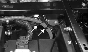
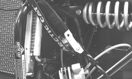
5.Tighten the remaining cap screws; then connect the electrical plug to the main harness. 6.Turn the ignition switch to the ON position and check the operation by shifting the drive select switch several times. 7.Secure the wiring harness to the frame with a nylon cable tie; then install the inner fender panel. 8.Install the cap screws to secure the skid plate to the frame.
REMOVING 1.Remove the hubs (see Hub in this section). 2.Remove the belly panel. 3.Remove the drain plug and drain the gear lubricant into a drain pan; then install the plug and tighten to 45 in.-lb.
PR022A
4.Disconnect the front drive actuator connector from the main harness.
HDX291
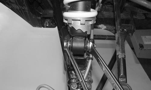
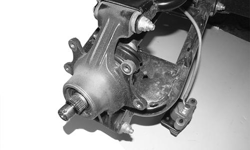
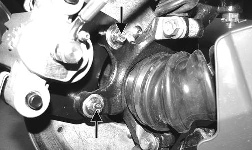
5.Remove the lower and upper ball joint cap screws taking care not to strip the threads on the ball joint shaft; then using a rubber mallet, tap the end of the axle and free it from the knuckle assembly.
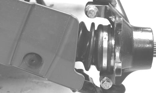
PR193
6.Pull the steering knuckle away from the axle.
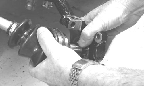
PR222
7.Support the axle to prevent it from dropping or hanging.
8.Remove the lower shock cap screws. Account for the lock nuts; then move the shocks and upper A-arm up and secure them with a strap.
CAUTION
The axle must be supported. If the axle is allowed to drop or hang, damage to the inner CV joint may occur.
PR200
9.Push the axle shaft toward the differential to release the “plunge” coupler; then remove the axle from the differential. Repeat for the opposite side.
PR729C
10.Remove the lower differential mounting cap screw.
Account for a lock nut and washers.
HDX292
11.Remove the upper differential mounting cap screw.
Account for a lock nut and two washers.
HDX377A
12.Match mark the front driveshaft flange to the rubber dampener. Remove the three patch lock cap screws and lock nuts. Discard the fasteners.
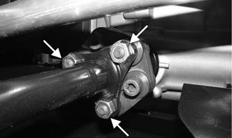
HDX361A
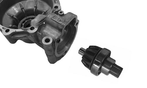
13.Free the differential assembly from the frame mountings and separate from the front driveshaft; then lower the differential through the frame. Account for the rubber boot and O-rings.
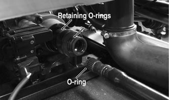
HDX379A
Disassembling Input Shaft NOTE: This procedure can be performed on a rear
gear case.
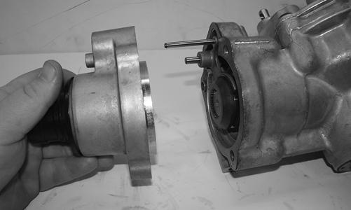
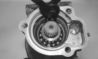
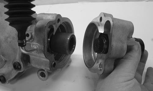
1.Using a T-40 torx wrench, remove the cap screws securing the pinion housing.
GC004A
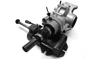
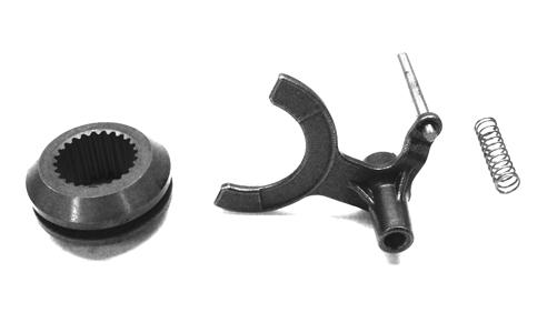
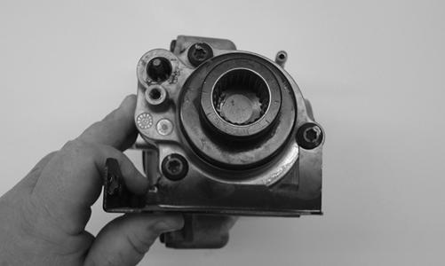
2.Using a rubber mallet, remove the housing. Account for a gasket. Remove the fork, collar, and spring.
Note the location of all the components for assembling purposes.
GC015 XR348
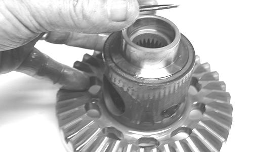
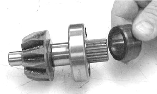
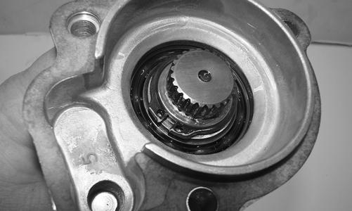
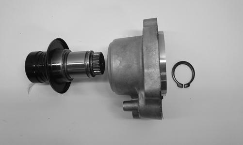
3.Remove the snap rings from the input shaft; then remove the input shaft from the pinion housing.
GC009A
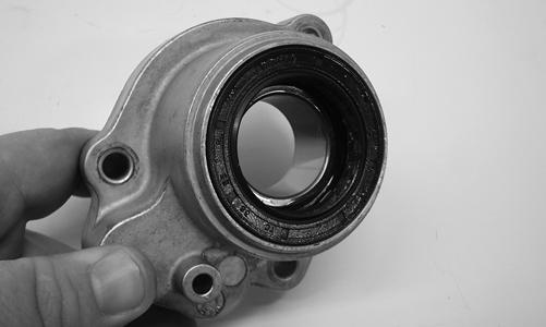
4.Using a seal removal tool, remove the input shaft seal. Account for a spacer.
GC010
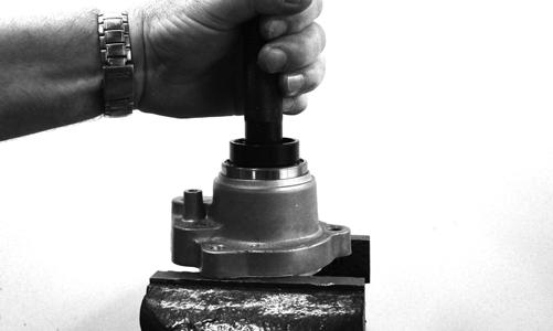
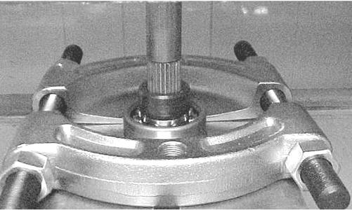
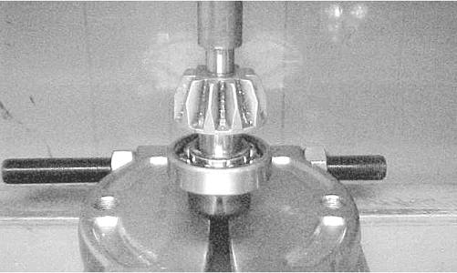
5.Remove the snap ring securing the input shaft bearing; then place the pinion housing in a press and remove the bearing.
XR350
XR351
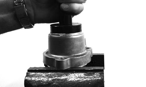
Assembling Input Shaft 1.Place the pinion housing in a press and install the input shaft bearing. Secure the bearing with the existing snap ring making sure the sharp edge of the snap ring faces to the outside.
GC012
GC011
2.Install the input shaft seal making sure it is fully seated in the edge of the housing.
GC014
3.Lubricate the input shaft with High-Performance #2
Molybdenum Disulphide Grease packing the splines; then assemble allowing excess grease to freely escape. Grease the pinion housing seal; then install the input shaft into the pinion housing and secure with a new snap ring. NOTE: Any time drive splines are separated, clean
all splines with parts-cleaning solvent and dry with compressed air; then lubricate with recommended grease.
GC009A
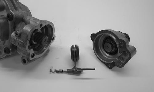
4.With the return spring over the shuttle shaft, place the shuttle shaft with O-ring into the differential housing.
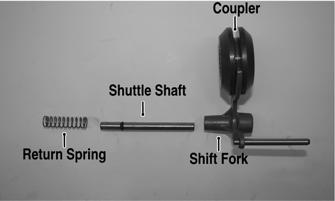
XR352A
XR354
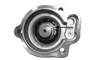
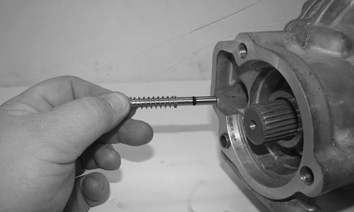
5.Place the dowel pin into the differential housing; then install a new gasket. Place the coupler onto the shift fork; then simultaneously engage the shift fork to the shuttle shaft and the internal splines of the coupler to the splines of the pinion gear shaft.
XR353
6.Align the splines of the output shaft to the internal splines of the coupler; then place the pinion housing onto the differential housing. If applicable, place the drive actuator bracket into position; then secure the assembly with three cap screws and tighten to 23 ftlb (existing) or 28 ft-lb (new differential housing).
XR347
Disassembling Differential Assembly NOTE: This procedure can be performed on a rear
gear case.
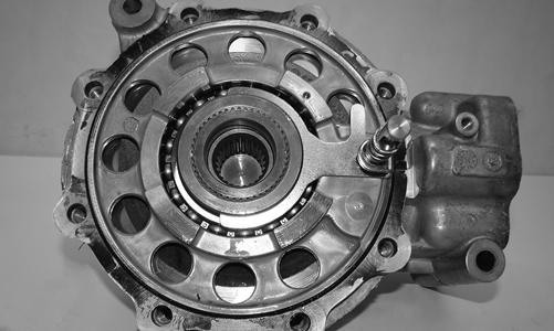
1.Using a T-40 torx wrench, remove the cap screws securing the pinion housing. Account for the coupler, fork, shuttle shaft with O-ring, and spring.
XR352A
2.Using a T-40 torx wrench, remove the cap screws securing the differential cover. 3.Using a plastic mallet, tap lightly to remove the differential cover. Account for an O-ring.
XR355
NOTE: If the cover is difficult to remove, pry on the
cover in more than one recessed location.
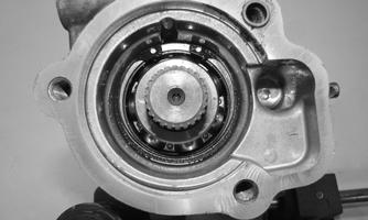
4.Remove the splined coupler, shifter fork, pin, and spring of the differential lock assembly and set aside.
Note position of parts for assembling purposes.
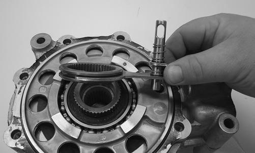
XR356
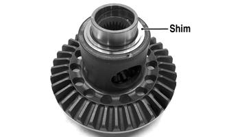
5.Remove the left differential bearing flange assembly and account for a shim. Mark the shim as left-side.
KX177
XR357
6.Place the differential with the open side down; then lift the housing off the spider assembly. Account for shim(s) and mark as right-side.
XR358
KX181
Disassembling Pinion Gear 1.Remove the internal snap ring securing the pinion bearing in the housing.
WC430
2.Using the Pinion Gear/Shaft Removal Tool and a hammer, remove the pinion gear from the gear case housing.
XR359
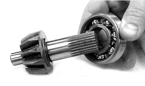
3.Secure the pinion gear in a bearing puller; then remove the pinion bearing using a press. Account for a collar and a bearing.
CC879
4.Remove any reusable parts from the gear case housing; then discard the housing and lock collar. Assembling Pinion Gear 1.Install the bearing onto the pinion shaft. Install the pinion shaft collar.
CC882
CC883
2. Place the pinion assembly in a bearing puller; then install the bearing using a press.
CC884
3.Using a propane torch, heat the gear case housing to approximately 200° F; then install the pinion assembly. 4.Install the internal snap ring with the sharp side directed away from the bearing.
Case-Side Shims (Backlash) p/n mm in. 0402-405 1.3 0.051 0402-406 1.4 0.055 0402-407 1.5 0.059 0402-408 1.6 0.063 0402-409 1.7 0.067
Cover-Side Shims (Ring Gear End-Play) p/n mm in.
1402-074 1.3 0.051 1402-075 1.4 0.055 1402-076 1.5 0.059 1402-077 1.6 0.063 1402-078 1.7 0.067 It is very important to adjust bevel gears for the proper running tolerances. Gear life and gear noise are greatly affected by these tolerances; therefore, it is very important to properly adjust any gear set prior to final assembly. The following procedure can be used on both front differential or rear drive gear case. NOTE: All bearings must be installed in the gear
case and the pinion properly installed before proceeding.
Backlash NOTE: Always set backlash prior to any other
shimming.
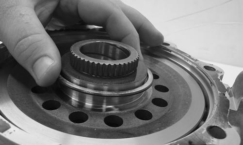
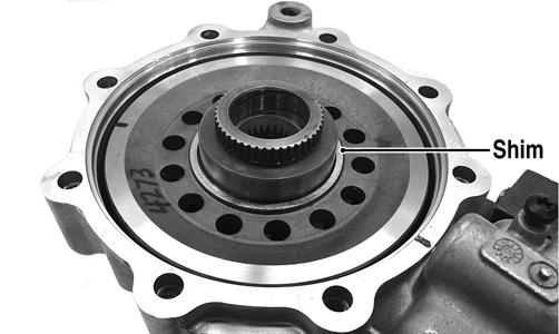
1.Install the existing shim or a 0.051-0.055-in. shim on the gear case side of the ring gear assembly.
GC031A
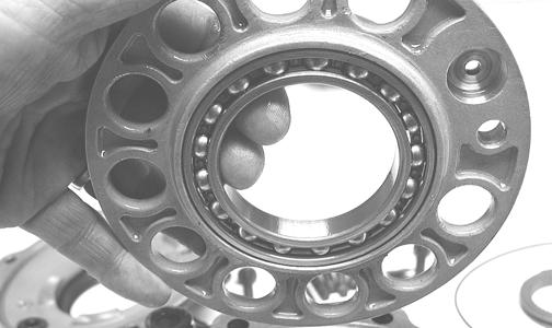
2.Install the ring gear with shim in the gear case; then while holding the pinion stationary, rock the ring gear forward and back to determine if any backlash exists. If no backlash exists, install a thicker shim and recheck.
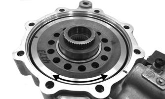
GC036A
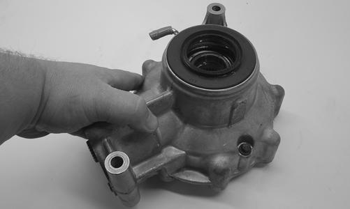
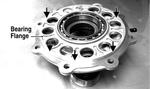
3.Install the bearing flange onto the gear case cover making sure the alignment/locating pin engages the locating hole in the cover; then make sure the bearing flange is completely seated in the cover.
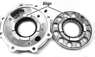
GC032A
GC033A
4.Install the existing shim or a 0.063 in. shim on the cover side of the ring gear; then place the assembled gear case cover onto the gear case and secure with three cap screws. Tighten evenly using a crisscross pattern.
GC036B
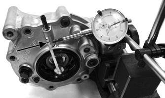
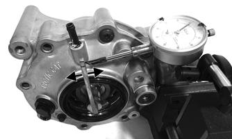
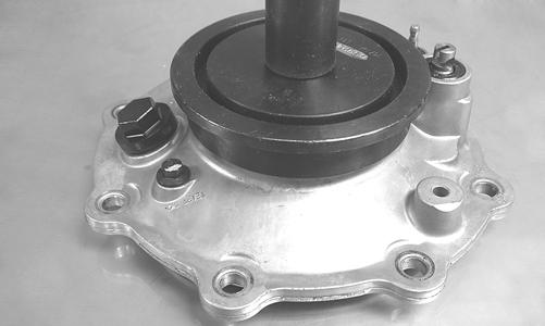
5.Place the appropriate Backlash Measuring Tool into the splines of the ring gear and install a dial indicator making sure it contacts the gauge at a 90° angle and on the index mark.
GC040
GC039A
6.Zero the dial indicator; then while holding the pinion stationary, rock the ring gear assembly forward and back and record the backlash. Backlash must be 0.011-0.015 in. If backlash is within specifications, proceed to Ring Gear End-Play. If backlash is not within specifications, increase shim thickness to increase backlash or decrease shim thickness to decrease backlash.
NOTE: Higher backlash settings usually result in
quieter gear operation.
GC037A
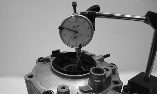
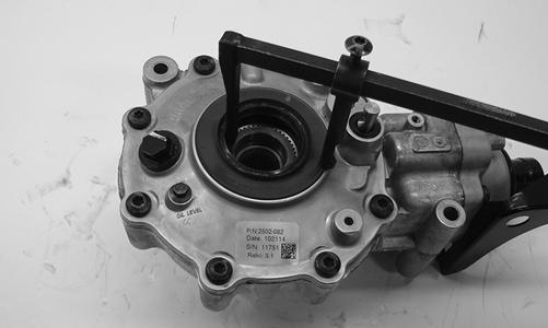
Ring Gear End-Play After correcting backlash, ring gear end-play can be adjusted. To adjust end-play, use the following procedure. 1.Secure the gear case in a holding fixture with the cover side up; then install a dial indicator contacting the ring gear axle flange.
GC035
2.Zero the dial indicator; then push the ring gear toward the dial indicator and release. End-play should be 0.004-0.008 in. 3.To increase end-play, decrease the shim thickness. To decrease end-play, increase the shim thickness. NOTE: Once proper backlash and end play are
established, the gear case can be assembled.
Assembling Differential Assembly 1.With the pinion gear and new bearings installed, place the selected (backlash) shim on the gear case side of the ring gear with the chamfered side toward the ring gear; then install into gear case/differential housing.
GC031A
GC020
2.Place the selected (end-play) shim, chamfered side toward the gear, onto the cover side of the ring gear.
GC036B
NOTE: The spider and ring gear assembly must be
replaced as a complete unit.
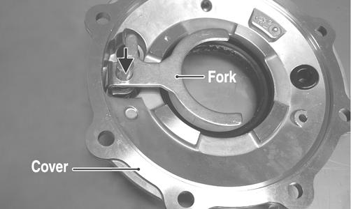
3.Assemble the fork and sliding collar into the cover assembly; then install the left bearing flange/bearing assembly and seat firmly into the cover.
CF266A
CF267A
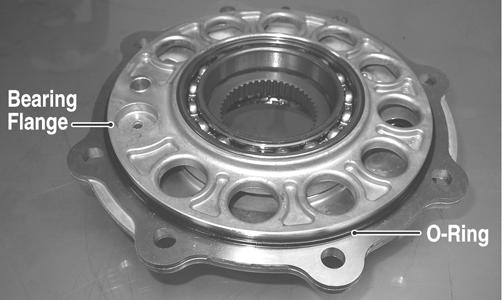
4.Apply a liberal coat of grease to the O-ring; then install it on the assembled cover assembly making sure to seat the O-ring completely down around the circumference of the bearing flange.
CF275A
5.Making sure the O-ring is properly positioned on the differential housing cover assembly, install the cover with existing cap screws (coated with green Loctite #270). Tighten the cap screws evenly to 23 ft-lb. NOTE: Grease can be applied to the O-ring for ease
of assembling.
NOTE: If a new housing is being installed, tighten
the cap screws to 28 ft-lb.
6.Install the shift fork shaft w/spring into the housing making sure the shaft O-ring is positioned to the inside.
XR354
7.Install the shift fork assembly making sure the fork leg is facing upward. Apply a small amount of oil to the gasket; then install the gasket.
XR353
8.Place the input shaft assembly onto the gear case housing; then with the actuator bracket in place, secure with the existing cap screws. Tighten to 23 ftlb.
NOTE: If a new housing is being installed, tighten
the cap screws to 28 ft-lb.
XR347
Removing/Installing Axle Seal NOTE: This procedure can be performed on a rear
gear case.
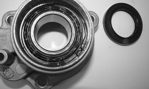
1.Remove the seal using a seal removal tool.
XR360
NOTE: Prior to installing the seal, apply High-Per-
formance #2 Molybdenum Disulphide grease to the seal outside diameter.
2.Using Gear Case Seal Installer Tool, evenly press the seal into the cover bore until properly seated.
CF278
CAUTION
Make sure the tool is free of nicks or sharp edges or damage to the seal may occur.
3. Repeat steps 1-2 for the opposite side. INSTALLING DIFFERENTIAL 1.With the rubber boot and O-rings set in place, place the differential assembly into position in the frame engaging the front propeller shaft; then install the top mounting cap screw, two washers, and lock nut. Do not tighten at this time.
HDX379A
2.Install the lower differential mounting cap screw, washers, and lock nut. Tighten the differential to frame cap screws and lock nuts to 42 ft-lb.
HDX292
3.Pour 269 ml (9.1 fl oz) of SAE 80W-90 hypoid lubricant into the differential and install the fill plug.
Tighten to 16 ft-lb. 4.Align thepreviously made match marks on the front driveshaft and the rubber coupler; then install new
Patch-lock cap screws and lock nuts and tighten to 20 ft-lb.
HDX361A
5.Install the front axles. 6.Install the knuckle assemblies onto the axles and ball joints; then secure with four cap screws taking care not to damage the threads when installing. Tighten to 35 ft-lb.
PR201
PR193
7.Secure the lower shock eyelets with cap screws and lock nuts. Tighten to 42 ft-lb.
HDX293
8.Connect the front drive actuator connector to the main harness; then secure the wires to the frame with nylon ties. 9.Apply a light coat of multi-purpose grease to the hub splines; then install the hubs (see Hub in this section). 10. Install the wheels and using a crisscross pattern, tighten the wheel nuts in 20 ft-lb increments to a final torque of 40 ft-lb (steel wheel), 60 ft-lb (aluminum wheel w/black nuts), or 80 ft-lb (aluminum wheel w/ chrome nuts). 11.Remove the vehicle from the support stand. 12.Install the belly panel.
Drive Axles
REMOVING REAR DRIVE AXLE 1.Remove the hubs (see Hub in this section). 2.Remove the cap screw and lock nut securing the knuckle to the upper A-arm. Discard the lock nut.
PR962
3.While holding the drive axle stationary, pull the top of the knuckle out and down until it is free of the drive axle.
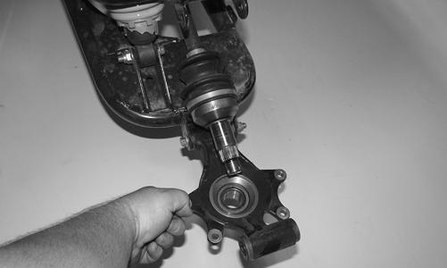
PR963
4.Place a drain pan under the vehicle to contain any oil leakage; then pushing the axle shaft in, pull the axle assembly from the gear case.
PR729C
REMOVING FRONT DRIVE AXLE NOTE: For removing a front drive axle, see Front
Differential in this section.
CLEANING AND INSPECTING AXLES NOTE: Always clean and inspect the drive axle
components to determine if any service or replacement is necessary.
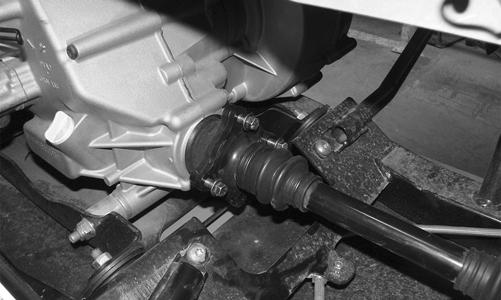
1.Using a clean towel, wipe away any oil or grease from the axle components.
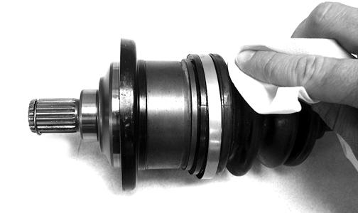
CD019
2.Inspect boots for any tears, cracks, or deterioration. NOTE: If a boot is damaged in any way, it must be
replaced with a boot kit.
DISASSEMBLING AXLES NOTE: Only the boots are serviceable on the axles;
if any other component is worn or damaged, the axle must be replaced.
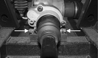
1.Using CV Boot Clamp Tool, remove and retain both clamps for assembly purposes.
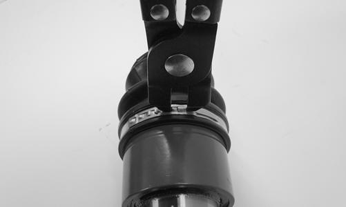
HDX390
2.Use a suitable form of protection on the outside surface of the CV joint, such as a strip of rubber or duct tape; then place the CV joint housing into a vise.
CAUTION
Do not over tighten the vise when securing the CV joint housing, otherwise internal damage to the CV joint may occur.
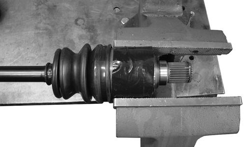
CF335HDX391
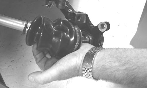
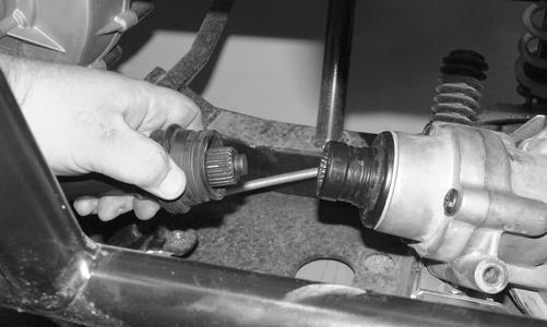
3.To disengage the axle from the CV joint, sharply pull back on the axle; then slide the boot off of the axle.
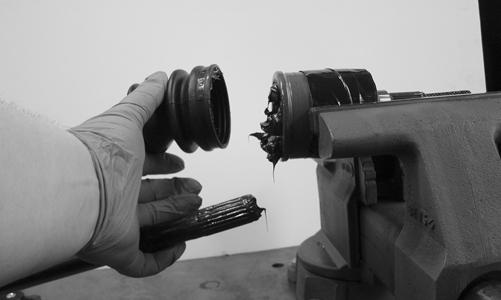
HDX392
NOTE: Steps 1-3 can be used to replace the out-
board boot.
ASSEMBLING AXLES 1.Install the inner boot with the small clamp making sure the ends of the clamp are positioned correctly. NOTE: Position the end of the clamp opposite the
forward rotation of the axle.
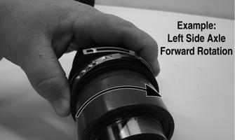
HDX393A
NOTE: The boot is positioned correctly when the
small end of the boot seats down into the recessed groove.
2.Using the boot clamp tool, secure the small clamp of the inner boot.
ATV-1048
3.Apply 80 grams (2/3 of contents) of grease from the pack into the bearing housing.
4.Check the condition of the circlip on the end of the half shaft and replace if necessary. Engage the external splines on the end of the half shaft into the starshaped inner race of the CV joint; then grasp the half shaft and seat it into the CV joint assembly by pressing it firmly into the CV joint assembly. 5.Using the boot clamp pliers, install the large diameter boot clamp. NOTE: Steps 1-5 can be used to replace the out-
board boot.
NOTE: In the outboard boot, use the final 40 grams
(1/3 of contents) of grease from the pack in the bearing housing.
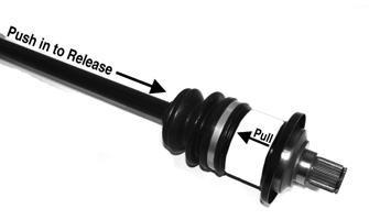
INSTALLING REAR DRIVE AXLE 1.Push the axle shaft into the CV coupler to release the lock ring; then slide the drive axle into place in the gear case.
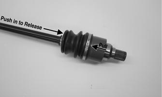
HDX389A
NOTE: To ensure proper axle seating, give it a light
pull; the axle should remain “clipped” in place.
2.Swing the knuckle up and onto the drive axle; then place the knuckle into place in the upper A-arm.
Secure the knuckle to the A-arm with a cap screw and a new lock nut. Tighten to 35 ft-lb. 3.Install the hubs (see Hub in this section). 4. Install the wheels and using a crisscross pattern, tighten the wheel nuts in 20 ft-lb increments to a final torque of 40 ft-lb (steel wheel), 60 ft-lb (aluminum wheel w/black nuts), or 80 ft-lb (aluminum wheel w/ chrome nuts). 5.Remove the vehicle from the support stand and release the parking brake. INSTALLING FRONT DRIVE AXLE 1.Push the axle shaft into the CV coupler to release the lock ring; then position the drive axle in the gear case and steering knuckle; then insert the ball joints into the steering knuckles. Secure with cap screws tightened to 35 ft-lb. 2.Secure the lower shock eyelet to the A-arm with a cap screw and a new lock nut. Tighten to 42 ft-lb. 3.Install the hubs (see Hub in this section).
4. Install the wheels and using a crisscross pattern, tighten the wheel nuts in 20 ft-lb increments to a final torque of 40 ft-lb (steel wheel), 60 ft-lb (aluminum wheel w/black nuts), or 80 ft-lb (aluminum wheel w/ chrome nuts). 5.Remove the vehicle from the support stand. 6.Check the front differential lubricant level and add lubricant as necessary.
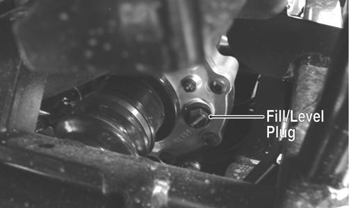
PR065A
Rear Gear Case
REMOVING NOTE: For backlash and end play procedures, see
Front Differential section.
1.Release the cargo box latch and allow the cargo box to tilt back; then remove the left side storage box. 2.Drain the lubricant from the rear gear case; then remove both rear drive axles. 3.Remove the four cap screws securing the driveline flange to the engine flange.
HDX277
4.Remove the front and rear cap screws and lock nuts securing the rear gear case to the frame bracket.
Account for the washers and their locations. Discard the lock nuts.
HDX278A
5.Remove the propeller shaft from the rear gear case.
Account for the boot and boot O-rings.
HDX279
6.Remove the gear case through the furthest rear opening of the frame and lift out the top.
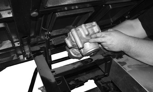
HDX280
AT THIS POINT
For servicing the input shaft, pinion gear, needle bearing, ring gear, and axle seals, see Front Differential in this section.
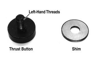
RING GEAR/THRUST BUTTON Removing 1.Remove the cap screws securing the gear case cover to the gear case; then remove the ring gear. 2.Remove the thrust button from the gear case cover (left-hand threads). Account for a shim. Inspecting 1.Inspect the ring gear for excessive wear, missing or chipped teeth, or discoloration.
2.Inspect the thrust button for excessive wear or discoloration. 3.Inspect the bearings for discoloration, roughness, or excessive wear. Installing/Shimming NOTE: Ring gear clearance must be adjusted prior
to selecting shim for the thrust button.
1.Install the thrust button with shim into the gear case cover and tighten securely (left-hand threads).
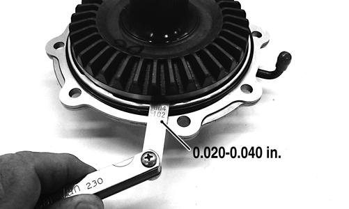
GC057A
2.Place the ring gear with selected shim into the cover and measure the ring gear to thrust button clearance with a thickness gauge. Clearance should be 0.0200.040 in.
GC058A
3.If clearance is as specified, remove the ring gear and thrust button; then place a drop of red Loctite #271 on the threads and tighten to 8 ft-lb (left-hand threads). 4.If clearance is not as specified, repeat steps 1 and 2 using thicker shim (clearance too great) or thinner shim (clearance too small) until correct specification is reached. REAR DRIVE INPUT SHAFT/HOUSING Removing/Disassembling 1.Remove the cap screws securing the rear drive input shaft/housing to the rear gear case; then remove the input housing assembly. Account for a gasket and dowel pin.
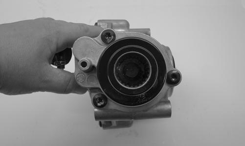
HDX380
HDX381
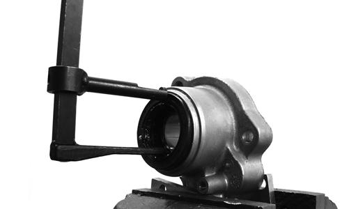
2.Remove the snap ring securing the input shaft to the housing bearing; then remove the shaft.
HDX382
HDX383
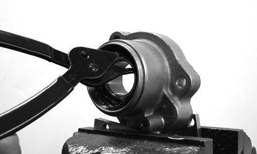
3.Using an appropriate seal puller, remove the seal from the front of the housing.
HDX384
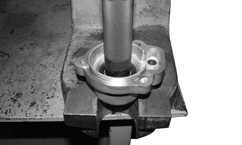
4.Remove the snap ring retaining the input bearing and using an appropriate bearing driver, press the bearing from the housing.
HDX385
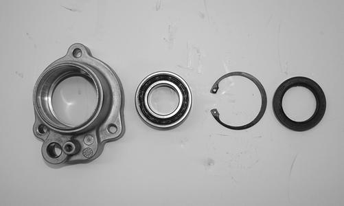
Cleaning and Inspecting 1.Wash all parts in parts cleaning solvent and dry with compressed air.
! WARNING
Always wear safety glasses when working with compressed air.
2.Clean all gasket material and sealant from mating surfaces. 3.Inspect bearings, shafts, and housing for excessive wear, cracks, or discoloration. Assembling/Installing 1.Install a new bearing into the input housing and secure with the snap ring (flat side directed away from bearing).
2.Using a suitable seal driver, install a new oil seal into the front of the input housing until the seal is flush with the housing.
HDX384
3.Apply grease to the lips of the oil seal; then install the input shaft into the input bearing and housing.
Install the snap ring.
HDX383
HDX382
4.Using a new gasket and with the dowel pin set in place, install the assembled rear drive input shaft/ housing onto the rear drive gear case and secure with the three cap screws. Tighten to 23 ft-lb..
INSTALLING 1.Slide the gear case into position down through the upper-right side of the frame; then align the driveline splines to the gear case input coupler and engage the driveshaft and gear case. 2.Lubricate the splines of the driveshaft with the appropriate grease; then align and engage the driveline flange to the engine flange. Tighten to 20 ft-lb. 3.Secure the gear case to the frame/frame bracket with two through-bolts and secure with lock nuts and flat washers. Tighten to 42 ft-lb. 4.Install the rear drive axles; then install the brake calipers and tighten the new “patch-lock” cap screws to 20 ft-lb. 5.Fill the gear case with the appropriate lubricant; then install the left side storage box.
AT THIS POINT
For servicing the input shaft, pinion gear, needle bearing, and axle seal, see Front Differential in this section.
Hub
REMOVING 1.Secure the vehicle on a support stand to elevate the wheel; then remove the wheel(s). NOTE: The jack stands should be placed under the
main frame to avoid contact with front suspension components.
NOTE: Removing or tightening of the hub nuts
requires the axles be locked. To lock the rear axle, place the transmission in park. To lock the front axle, turn the ignition switch to ON and select LOCK on the drive select switch; then place the transmission in park and turn the ignition switch to OFF.
! WARNING
Make sure the vehicle is solidly supported on the support stand to avoid injury.
2.Remove the hub retaining plate.
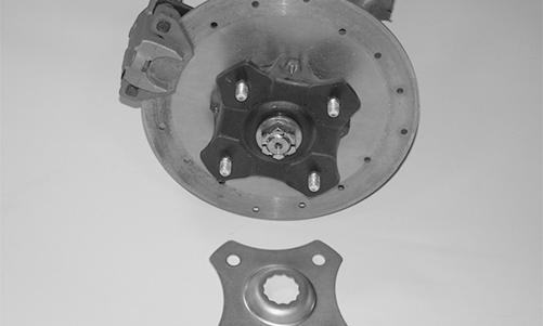
PR960
3.Remove the hub nut securing the hub. 4.Remove the brake caliper(s). NOTE: It is not necessary to remove the brake hoses
from the calipers for this procedure.
PR264A
5.Remove the hub assembly. 6.Remove the four cap screws securing the brake disc.

PR254A
CLEANING AND INSPECTING 1.Clean all hub components. 2.Inspect all threads for stripping or damage. 3.Inspect the brake disc (if applicable) for cracks or warping. 4.Inspect the hub for pits, cracks, loose studs, or spline wear. REPLACING WHEEL STUDS 1.Secure the hub in a suitable holding fixture and remove the brake disc (if applicable). 2.Drive the damaged stud out of the hub; then place the new stud into the hub and thread on an appropriate flange nut.
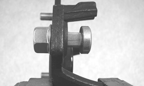
PR250
3.Using a socket and ratchet handle, tighten the nut until the stud is fully drawn into the hub.
PR252A
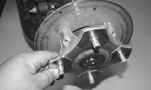
INSTALLING 1.Secure the brake disc (if applicable) to the hub with the four cap screws coated with red Loctite #271.
Tighten to 15 ft-lb. 2.Apply grease to the splines in the hub.
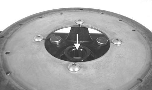
PR254B
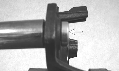
3.Install the hub assembly onto the axle; then place the transmission in park.
PR961
4.Secure the hub assembly with the nut. Tighten to 200 ft-lb; then install the hub retaining plate. NOTE: If the hub retaining plate cannot be inserted
due to misalignment of the hole in the axle and the slots in the nut, tighten the nut until properly aligned.
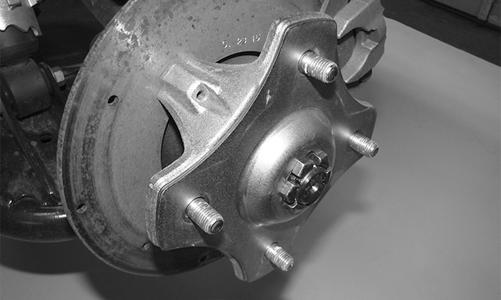
PR965
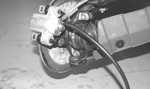
5.Secure the brake calipers to the knuckle with two new “patch-lock” cap screws tightened to 20 ft-lb.
PR264A
6. Install the wheels and using a crisscross pattern, tighten the wheel nuts in 20 ft-lb increments to a final torque of 40 ft-lb (steel wheel), 60 ft-lb (aluminum wheel w/black nuts), or 80 ft-lb (aluminum wheel w/ chrome nuts). 7.Remove the vehicle from the support stand.
Hydraulic Brake Caliper
! WARNING
Arctic Cat recommends only authorized Arctic Cat ROV dealers perform hydraulic brake service. Failure to properly repair brake systems can result in loss of control causing severe injury or death.
REMOVING/DISASSEMBLING 1.Secure the vehicle on a support stand to elevate the wheel; then remove the wheel.
! WARNING
Make sure the vehicle is solidly supported on the support stand to avoid injury.
! WARNING
Never let brake fluid contact the eyes. Damage to the eyes will occur. Always wear appropriate protective safety goggles and latex gloves when handling brake fluid.
2.Drain the brake fluid from the caliper, hose, and master cylinder through the bleed screw by pumping the brake pedal.
PR235
CAUTION
Brake fluid is highly corrosive. Do not spill brake fluid on any surface of the vehicle and do not reuse brake fluid.
NOTE: Whenever brake components are removed,
disassembled, or repaired where brake fluid is exposed to air, drain all fluid and replace with new DOT 4 brake fluid from an unopened container. Brake fluid readily absorbs moisture from the air significantly lowering the boiling point. This increases the chance of vapor lock reducing braking power and increasing stopping distance.
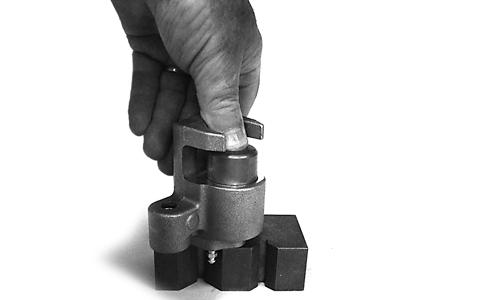
3.Remove the brake hose from the caliper and close the bleed screw; then remove the caliper. 4.Compress the caliper holder against the caliper (opposite the O-ring side) and remove the outer brake pad; then remove the inner brake pad. NOTE: If brake pads are to be returned to service,
do not allow brake fluid to contaminate them.
PR237A
PR238
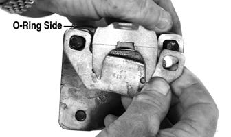
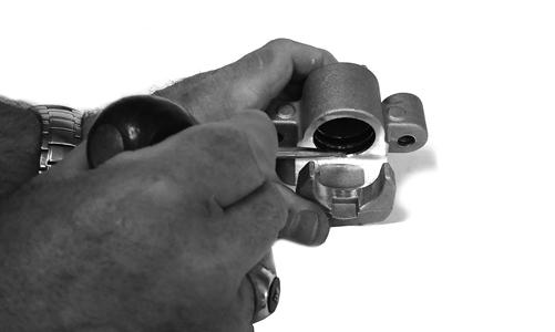
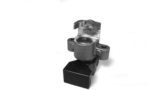
5.Remove the caliper holder from the caliper and discard the O-ring.
PR239B
NOTE: The O-ring is used for shipping purposes
and provides no function in operation.
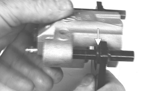
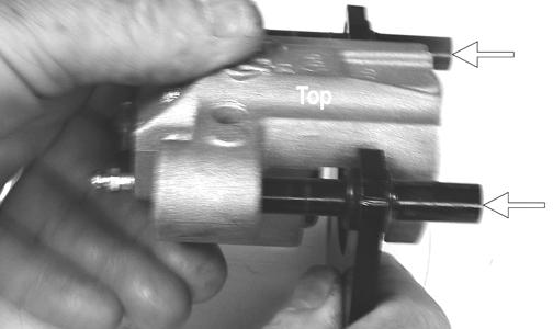
6.Cover the piston end of the housing with a shop towel; then keeping fingers clear of piston travel, apply compressed air to the fluid port to blow the piston free of the housing. Account for two seal rings in the housing.
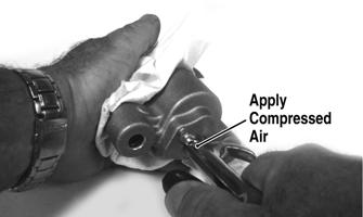
PR713A PR715
! WARNING
Make sure to hold the towel firmly in place or the piston could be ejected from the housing causing injury.
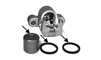
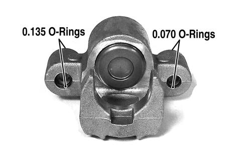
7.Using an appropriate seal removal tool, carefully remove the seals from the brake caliper housing; then remove four O-rings from the brake caliper housing noting the location of the different sized Orings. Discard all seals, O-rings, and crush washers. CLEANING AND INSPECTING 1.Clean all caliper components (except the brake pads) with DOT 4 brake fluid. Do not wipe dry. 2.Inspect the brake pads for damage and excessive wear.
NOTE: For measuring brake pads, see Periodic
Maintenance/Tune-Up - Hydraulic Brake System.
3.Inspect the brake caliper housings for scoring in the piston bores, chipped seal ring grooves, or signs of corrosion or discoloration. 4.Inspect the piston surface for scoring, discoloration, or evidence of binding or galling. 5.Inspect the caliper holder for wear or bending. ASSEMBLING/INSTALLING 1.Install new seals into the brake caliper housing and apply a liberal amount of DOT 4 brake fluid to the cylinder bore of the housing, seals, and brake piston.
CAUTION
Make sure the seals are properly in place and did not twist or roll during installation.
PR717A
2.Press the piston into the caliper housing using hand pressure only. Completely seat the piston; then wipe off any excessive brake fluid.
PR711A
PR712
3.Apply high-temperature silicone grease (supplied with the O-ring kit) to the inside of the caliper holder bores and O-rings; then install the four O-rings into the caliper.
PR719C
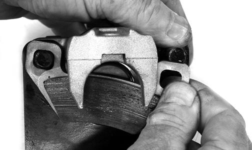
4.Install the caliper onto the caliper holder making sure the caliper and holder are correctly oriented.
PR239C
5.Making sure brake fluid does not contact the brake pads, compress the caliper holder toward the caliper and install the inner brake pad; then install the outer pad.
CAUTION
If brake pads become contaminated with brake fluid, they must be thoroughly cleaned with brake cleaning solvent or replaced with new pads. Failure to do so will result in reduced braking and premature brake pad failure.
PR238

PR239
6.Place the brake caliper assembly into position and secure with new “patch-lock” cap screws. Tighten the caliper to 20 ft-lb. 7.Place a new crush washer on each side of the brake hose fitting and install it on the caliper. Tighten to 20 ft-lb.
8.Fill the reservoir; then bleed the brake system (see
Periodic Maintenance/Tune-Up - Hydraulic Brake
System).
! WARNING
Never use brake fluid from an open container or reuse brake fluid. Moisture-contaminated brake fluid could cause vapor build-up (expansion) during hard braking resulting in greatly increased stopping distance or loss of control leading to injury or death.
9. Install the wheels and using a crisscross pattern, tighten the wheel nuts in 20 ft-lb increments to a final torque of 40 ft-lb (steel wheel), 60 ft-lb (aluminum wheel w/black nuts), or 80 ft-lb (aluminum wheel w/ chrome nuts). 10.Remove the vehicle from the support stand and verify brake operation. MASTER CYLINDER ASSEMBLY NOTE: The master cylinder is a non-serviceable
component; it must be replaced as an assembly.
Removing 1.Slide a piece of flexible tubing over one of the wheel bleeder valves and direct the other end into a container. Remove the reservoir cover; then open the bleeder valve. Allow the brake fluid to drain until the reservoir is empty.
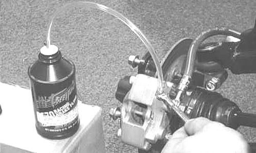
AF637D
2.Remove the banjo bolt and brake switch securing the banjo-fittings to the master cylinder.
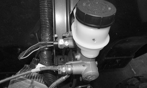
PR947
3.Remove the cotter pin and pivot pin from the yoke; then remove two cap screws and flange nuts securing the master cylinder assembly to the frame.
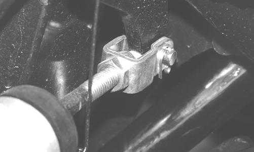
PR338
PR336
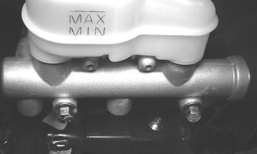
4.Remove the master cylinder. Discard the three crush washers.
Inspecting 1.Inspect the master cylinder push rod and clevis for wear, bending, or elongation of clevis holes. 2.Inspect the push rod boot for tears or deterioration. 3.Inspect the reservoir for cracks and leakage. 4.Inspect the brake hose for cracks and deterioration and the condition of the banjo-fittings. Installing 1.Secure the master cylinder assembly to the frame with two cap screws and two flange nuts. Tighten to 25 ft-lb. 2.Using new crush washers, secure the banjo-fittings to the master cylinder with a new banjo bolt and the existing brake switch. Tighten to 20 ft-lb. 3.Install the pivot pin and secure with a new cotter pin. 4.Fill the master cylinder and bleed the brake system (see Hydraulic Brake System in the Periodic Maintenance/Tune-Up section).
CAUTION
Brake fluid is highly corrosive. Do not spill brake fluid on any surface of the vehicle.
Troubleshooting Drive System
Troubleshooting Brake System
Problem: Power not transmitted from engine to wheels Condition Remedy
1. Rear axle shaft serration worn - broken 1.Replace shaft
Problem: Power not transmitted from engine to either front wheel Condition Remedy
1. Secondary drive - driven gear teeth broken 1.Replace gear(s) 2. Propeller shaft serration worn - broken 2.Replace shaft 3. Coupling damaged 3.Replace coupling 4. Coupling joint serration worn - damaged 4.Replace joint 5. Front drive - driven bevel gears broken - damaged 5.Replace gear(s) 6. Front differential gears/pinions broken - damaged 6.Replace gears - pinions 7. Front drive actuator not operating 7.Replace fuse - drive select switch - front drive actuator
Problem: Braking poor Condition Remedy
1. Pad worn 1.Replace pads 2. Brake fluid leaking 2.Repair - replace hydraulic system 3. Master cylinder/brake cylinder seal worn 3.Replace seal(s)
Problem: Brake pedal travel excessive Condition Remedy
1. Brake fluid low 1.Add fluid to proper level 2. Piston seal - cup worn 2.Replace seal - cup
Problem: Brake fluid leaking Condition Remedy
1. Connection fittings loose 1.Tighten fittings 2. Hose cracked 2.Replace hose 3. Piston seal worn 3.Replace seal
Problem: Brake pedal spongy Condition Remedy
1. Air trapped in hydraulic system 1.Bleed hydraulic system 2. Brake fluid low 2.Add brake fluid and bleed hydraulic brake system