11 minute read
Fuel/Lubrication/Cooling

TROUBLESHOOTING 1.Verify that the electric fuel pump is operating by listening for a “whirring” sound for several seconds after the ignition switch is turned to the ON position.
If no sound can be heard, see EFI Sensors/Components in Electrical System. 2.Check for a flashing EFI icon on the LCD. If EFI is flashing, see EFI Diagnostic System in Electrical
System. 3.Make sure there is sufficient, clean gas in the gas tank. SPECIAL TOOLS A number of special tools must be available to the technician when performing service procedures in this section. Refer to the current Special Tools Catalog for the appropriate tool description. NOTE: When indicated for use, each special tool
will be identified by its specific name, as shown in the chart below, and capitalized.
Description p/n
Oil Pressure Test Kit 0644-495 Tachometer 0644-275
NOTE: Special tools are available from the Arctic
Cat Service Department.
Throttle Body
! WARNING
Whenever the gasline hoses are removed (other than for pressure testing), the battery must be disconnected to prevent inadvertent activation of the electronic fuel pump.
! WARNING
Whenever any maintenance or inspection is performed on the fuel system during which there may be fuel leakage, there should be no welding, smoking, open flames, etc., in the area.
REMOVING 1.Turn the ignition switch to the OFF position; then remove the ignition switch key.
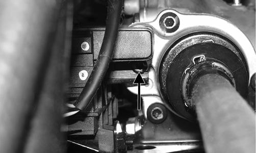
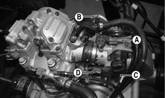
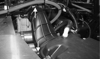
2.Remove the seat, seat back, and seat base; then disconnect the battery. 3.Remove the air inlet boot between the air filter and throttle body; then disconnect the MAP/TMAP sensor connector (A), fuel injector connector (B), ISC connector (C), and TPS connector (D).
! WARNING
Do not turn the ignition switch to the ON position with the hoses removed. Gasoline will be pumped by the electric fuel pump causing a safety hazard.
HDX366A
700
HDX136A
500
PK170C
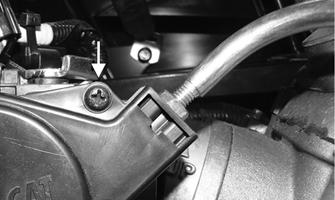
4.Remove the screw from the throttle arm cover and remove the cover; then loosen the jam nut and disconnect the throttle cable. The 500 utilizes two screws to secure the throttle arm cover.
! WARNING
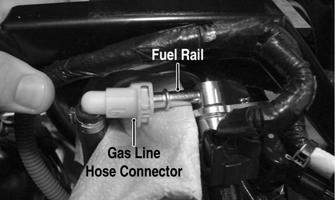
Gasoline may be under pressure. Place an absorbant towel under the connector to absorb any gasoline spray when disconnecting.
700
HDX367A
500
HDX449A
6.Loosen the clamp securing the throttle body to the intake manifold boot and remove the throttle body assembly. 7.Use tape to cover and seal the intake opening.
CAUTION
Any objects or liquid entering the intake opening will fall into the engine causing severe damage if the engine is turned over or started.
INSTALLING 1.Install the throttle body into the intake manifold boot and secure with the clamp. Tighten to 30 in.-lb. 2.Connect the throttle cable to the throttle body; then connect the gasline hose. 3.Connect the electrical connectors to the throttle body components. 4.Install the air filter boot and secure with the existing hardware. 5.Install the seat base, seat back, and seat. NOTE: If the throttle body, ECM, TPS, or ISC are
replaced, the EFI system must be synchronized. Use the following procedure.
1.With the key off, depress accelerator pedal to Wide
Open Throttle (WOT). 2.Place the ignition key in the ON position and wait for 10 seconds. 3.Release the accelerator pedal and wait an additional 10 seconds. 4.Turn the key to the OFF position and allow the gauge to shut off.
Gas Tank
! WARNING
Whenever any maintenance or inspection is made on the fuel system during which there may be fuel leakage, there should be no welding, smoking, open flames, etc., in the area.
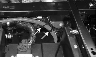
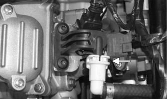
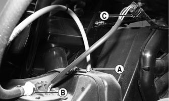
REMOVING 1.Remove the seat, seat back, seat base, and side panels; then remove the floorboard. 2.Disconnect the vent hose (A), gasline hose (B), and fuel pump/fuel level sensor connector (C); then cap the vent fitting and gas hose fitting.
HDX259A
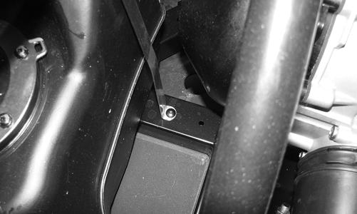
3.Remove the cap screws securing the front tank holddown to the frame.
HDX368
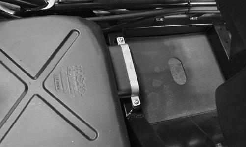
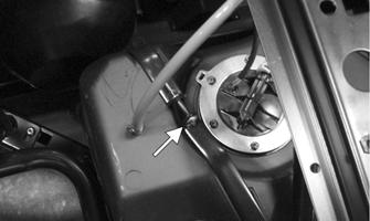
4.Remove the joining cap screw and nut from the rear gas tank hold-down strap; then remove the inside hold-down strap.
HDX369A HDX370
2.Install the front hold-down strap and secure with the two cap screws. Do not tighten at this time.
HDX370
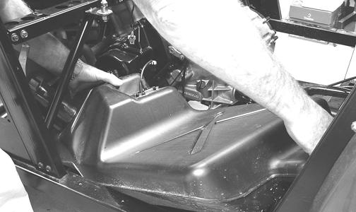
5.Lift and slide the tank forward raising the front of the tank first; then turn the tank and lift out the right side. CLEANING AND INSPECTING 1.Clean all gas tank components with parts-cleaning solvent. 2.Inspect all hoses for cracks or leaks. 3.Inspect gas tank cap and tank for leaks, holes, and damaged threads. 4.Inspect the fuel level sensor for proper operation (see
EFI Sensors/Components in Electrical System). INSTALLING
1.Place the gas tank into position in the vehicle; then install the inside rear hold-down strap.
! WARNING
Whenever any maintenance or inspection is made on the fuel system during which there may be fuel leakage, there should be no welding, smoking, open flames, etc., in the area.
HDX368
3.Install the rear hold-down strap joining cap screw and nut. Do not tighten at this time.
HDX369A
4.Place the gas cap filler panel into position; then if necessary, position the gas tank so the filler panel and filler neck are not binding or rubbing.
5.Tighten the hardware securing the hold-down straps (from steps 2-3) securely. 6.Connect the vent hose (A) and gasline hose (B) to the proper fittings; then connect the fuel pump/fuel level sensor connector (C) to the main harness.
HDX259A
7.Position the floorboard into the vehicle and secure with the appropriate hardware; then install the seat base, seat back, and seat.
Oil Pump
NOTE: Whenever internal engine components wear
excessively or break and whenever oil is contaminated, the oil pump should be replaced.
TESTING OIL PUMP PRESSURE NOTE: The engine must be warmed up to operating
temperature (cooling fan cycling) for this test.
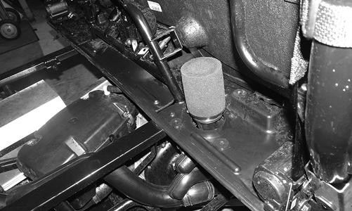
1.Remove the seat, seat back, and seat base. 2.Using a suitable “T” fitting, connect Oil Pressure
Test Kit to the oil fitting and hose. Tighten all clamps securely. NOTE: Some oil seepage may occur when installing
the oil pressure gauge. Wipe up oil residue with a cloth.
3.Block the wheels, place the transmission in neutral, and start the engine. Allow the engine to warm up to operating temperature (with cooling fan cycling). 4.Connect a suitable tachometer. With the engine running at 3000 RPM, the pressure gauge must show 0.7-1.4 kg/cm2 (10-20 psi). 5.Remove the test kit and tachometer from the vehicle and install the oil hose. Tighten the clamps securely. 6.Install the seat base, seat back, and seat. NOTE: If the oil pressure is lower than specified,
check for an oil leak, damaged oil seal, or defective oil pump.
NOTE: If the oil pressure is higher than specified,
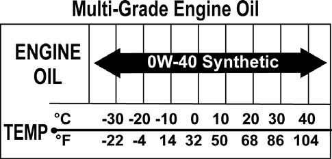
check for too heavy engine oil weight (see General Information/Foreword - Gasoline - Oil - Lubricant), clogged oil passage, clogged oil filter, or improper installation of the oil filter.
REMOVING/DISASSEMBLING 1.Remove the oil pump from the engine (see Right-
Side Components in the Engine/Transmission section). 2.Remove the Phillips-head screw on the back side of the pump and separate the pump housing and cover.
Note the position of the inner and outer rotors and alignment pin for assembly. 3.Remove oil pump components. CLEANING AND INSPECTING 1.Clean all oil-pump components. 2.Inspect the rotors for scoring and gouges. 3.Inspect the alignment pin, driveshaft, and driven sprocket for damage. 4.Inspect the pump housing and cover for cracks or damage. ASSEMBLING/INSTALLING 1.Place the rotors into the pump housing making sure the alignment pin is in the groove of the rotor. 2.Place the cover onto the pump housing. 3.Secure the pump cover with the Phillips-head screw coated with red Loctite #271. Tighten to 8 ft-lb. 4.Install the oil pump into the engine (see Right-Side
Components in the Engine/Transmission section).
Liquid Cooling System
When filling the cooling system, use premixed Arctic Cat Antifreeze. While the cooling system is being filled, air pockets may develop; therefore, open the bleed screw on the thermostat housing to allow air to bleed from the cooling system. When clear coolant (no bubbles) is present, tighten the bleed screw securely; then fill the cooling system to the bottom of the stand pipe in the radiator neck. Run the engine for five minutes after the initial fill, shut the engine off, and then “top-off” the cooling system to the bottom of the stand pipe in the radiator neck. NOTE: Use a good quality, biodegradable glycol-
based, automotive-type antifreeze. When filling the cooling system, use a 60/40 coolant/water mixture or one which will satisfy the coldest anticipated weather conditions of the area in accordance with the coolant manufacturer’s recommendations.
! WARNING
Never check the coolant level when the engine is hot or the cooling system is under pressure.
CAUTION
After operating the vehicle for the initial 5-10 minutes, stop the engine, allow the engine to cool down, and check the coolant level. Add coolant as necessary.
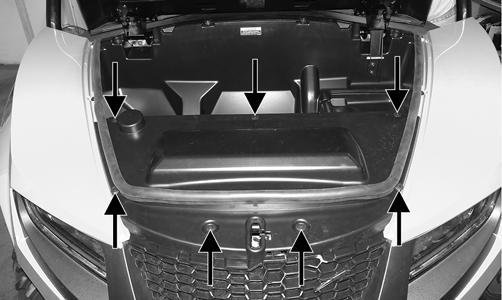
RADIATOR Removing 1.Open the hood and remove the weather strip; then remove the front access panel, front fenders, and front storage box.
PR890A
2.Drain the coolant into a suitable container; then disconnect the cooling fan wire connector from the main harness.
PR957
PR912A
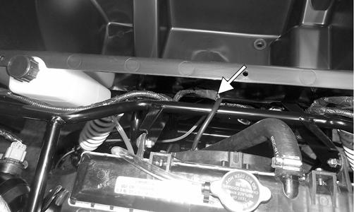
3.Remove the two shoulder bolts and nuts securing the radiator to the frame; then disconnect the upper and lower coolant hoses.
PR184A
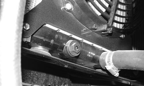
4.On the 700, remove the screws securing the oiler cooler to the radiator (two on each side). Place a protective cloth/cover over the oil cooler fins to prevent damage when removing the radiator.
HDX371A
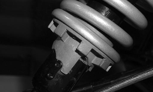
5.Lift the radiator assembly from the vehicle. Account for two upper and two lower rubber mounting grommets. Cleaning and Inspecting 1.Flush the radiator with water to remove any contaminants. 2.Inspect the radiator for leaks and damage. 3.Inspect all hoses for cracks and deterioration. 4.Inspect all fasteners and grommets for damage or wear. Installing 1.Place the radiator into position making sure the grommets are correctly installed; then secure to the mounts with the two shoulder bolts and nuts. Tighten to 8 ft-lb.
PR184A
2.On the 700, secure the oiler cooler to the radiator with four screws two located on each side.
HDX371A
3.Connect the upper and lower coolant hoses to the radiator and secure with the appropriate hose clamps; then connect the cooling fan wire connector to the main harness.
PR912A
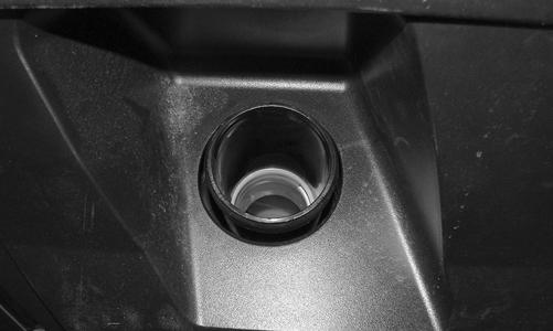
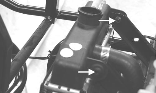
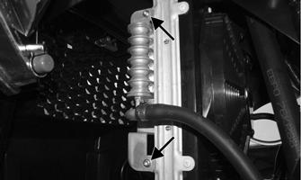
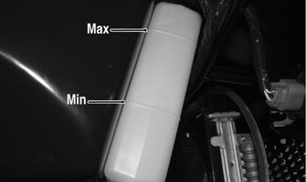
4.Open the high-point bleed screw on the top of the thermostat cover (700) or coolant outlet pipe (500) (located under the seat base) to allow trapped air to escape. Tighten securely after filling. 5.Pour the recommended coolant into the radiator and secure the radiator cap. Pour coolant into the reservoir tank up to the “MIN” marking.
HDX372A
6.Install the front storage box, front fenders, and front access panel. Close the hood. 7.Start the engine and warm up to operating temperature. Allow the engine to completely cool; then verify the coolant level is at the bottom of the stand pipe in the radiator neck. Add coolant as necessary. 8.Install the front access panel and the weather strip. THERMOSTAT Removing 1.Drain approximately one quart of coolant from the cooling system. 2.Remove the two cap screws securing the thermostat housing to the cylinder head (700) or thermostat housing (500). Account for a thermostat with seal. Inspecting 1.Inspect the thermostat for corrosion, wear, or spring damage. 2.Using the following procedure, inspect the thermostat for proper operation. A.Suspend the thermostat in a container filled with water. B.Heat the water and monitor the temperature with a thermometer. C.On the 700, the thermostat should start to open at 63.5-66.5° C (146-151° F). On the 500, the thermostat should start to open at 80-84°C (176-183°F), D.If the thermostat does not open, it must be replaced. 3.Inspect all coolant hoses, connections, and clamps for deterioration, cracks, and wear. NOTE: All coolant hoses and clamps should be
replaced every four years or 4000 miles.
Installing 1.Place the thermostat with seal into the thermostat housing (500) or cylinder head (700); then secure the thermostat housing cover with the two cap screws.
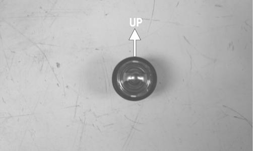
CAUTION
When installing the thermostat, make sure the bleed holes are straight up and down or air will remain trapped causing engine damage due to overheating.
PR281A
2.Fill the cooling system with the recommended amount of antifreeze. Check for leakage.
COOLING FAN Removing 1.Remove the radiator. 2.Remove the fan assembly from the radiator. Installing 1.Position the fan assembly on the radiator; then secure with existing hardware. NOTE: The fan wiring must be in the upper-right
position.
2.Install the radiator. WATER PUMP NOTE: On the 700, the water pump is a non-ser-
viceable component. It must be replaced as an assembly (see Left-Side Components). On the 500 to service the water pump, see Servicing Left-Side Components.
Troubleshooting
Problem: Starting impaired Condition Remedy
1. Gas contaminated 1.Drain gas tank and fill with clean gas
Problem: Idling or low speed impaired Condition Remedy
1. TPS out of adjustment 1.Adjust TPS
Problem: Medium or high speed impaired Condition Remedy
1. High RPM “cut out” against RPM limiter 1.Decrease RPM speed