13 minute read
Suspension

The following suspension system components should be inspected periodically to ensure proper operation. A.Shock absorber rods bent, pitted, or damaged. B.Rubber damper cracked, broken, or missing. C.Shock absorber body damaged, punctured, or leaking. D.Shock absorber eyelets broken, bent, or cracked. E.Shock absorber eyelet bushings worn, deteriorated, cracked, or missing.
F.Shock absorber spring broken or sagging. G.Sway bar mountings tight and bushings secure. SPECIAL TOOL A special tool must be available to the technician when performing service procedures in this section. Refer to the current Special Tools Catalog for the appropriate tool description. NOTE: When indicated for use, each special tool
will be identified by its specific name, as shown in the chart below, and capitalized.
Description p/n
Fox Shock Air Pump 2603-614 Spring Removal Tool 0644-057
NOTE: Special tools are available from the Arctic
Cat Service Department.
Shock Absorbers
Each shock absorber should be visibly checked weekly for excessive fluid leakage (some seal leakage may be observed but it does not indicate the shock is in need of replacement), cracks or breaks in the lower case, or a bent shock rod. If any one of these conditions is detected, replacement is necessary. NOTE: When the vehicle is operated in extremely
cold weather (-23° C/-10° F or colder), a small amount of leakage may be present. Unless the leakage is excessive, replacement is not necessary.
This vehicle is equipped with adjustable shock assemblies in the front and rear to allow for different driving and loading conditions. The front shock absorbers have an adjustment sleeve with five preload adjustment positions that can be turned with the spanner wrench to increase or decrease coil spring tension. To adjust the spring force on these shock absorbers, rotate the preload adjustment sleeve with a suitable spanner wrench until desired spring tension is achieved.
Position Spring Force Setting Load
1 Soft Light 2 3 4
5 Stronger Stiff Heavy
PR015
NOTE: Before attempting to adjust suspension,
clean dirt and debris from the sleeve and remove load from the suspension; then use the spanner wrench to adjust the sleeve to the desired position.
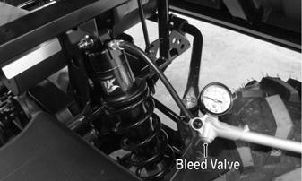
On the 700, the rear shock absorbers combine fixed preload springs and a variable air assist to provide adjustment allowing for differing driving and loading conditions. To adjust air pressure on these shock absorbers, connect the air pump to the valve fitting on the top of the shock absorber and pump (to increase pressure) or depress bleed valve (to decrease pressure) until desired pressure is achieved.
NOTE: For proper air pressure in rear shocks, use
the following recommended settings. The vehicle must be lifted off the ground with the shocks fully extended. Do not rapidly fill shocks. Shocks may lose air over time. Check pressure periodically.
Payload Pressure
0-300 lb 15 psi 300-600 lb 60 psi (min) 600-900 lb 90 psi (min) 900-1750 lb 150 psi
HDX087A
REMOVING 1.Secure the vehicle on a support stand to elevate the wheels and to release load on the suspension.
2.Remove the upper and lower mounting cap screws and lock nuts. Discard the lock nuts. Account for bushings and O-rings from each (rear only).
! WARNING
Make sure the vehicle is solidly supported on the support stand to avoid injury.
FRONT
HDX293
REAR 700
HDX294
3.For the 500 and 700 front shocks using a suitable spring compressor, compress the spring and remove the retainer ring.
HDX336
4.Carefully release the spring pressure and remove the spring. Account for the spring retainer.
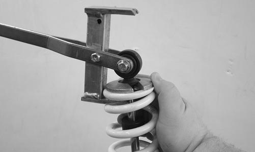
CLEANING AND INSPECTING 1.Clean all shock absorber components in parts-cleaning solvent. 2.Inspect each shock rod for nicks, pits, rust, bends, and oily residue. 3.Inspect all springs, spring retainers, shock rods, sleeves, bushings, shock bodies, and eyelets for cracks, leaks, and bends. INSTALLING 1.Place the shock absorber spring over the shock absorber, compress the spring, and install the retainer. 2.Place bushings and O-rings (where appropriate) into the shock eyelet; then install the shock absorbers with two cap screws and new nuts. Tighten to 42 ftlb. 3.Remove the vehicle from the support stand. Rear Shock Absorber Spring (700) REMOVING 1.Using soft jaws or a shop towel, secure the bottom shock assembly eyelet into a vise; then, using readily available shock spring compressors, install the spring compressors onto the spring towards the bottom end of the assembly.
! WARNING
Shock absorber springs are under high compression loads. Do not attempt to remove springs without an adequate spring compressor. Severe injury could result.
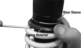
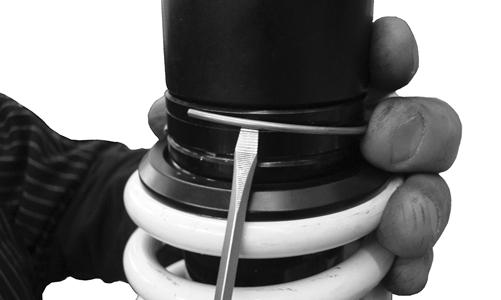
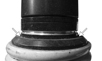
2.Compress the spring until approximately one inch of clearance is obtained between the top of the spring and top spring retainer. 3.Hold the wear sleeve up by using a flat blade screwdriver or small pry bar; then pull the spring retainer down to access the circlip. Note the installed location of the circlip for assembly purposes. NOTE: Place a piece of duct tape around the outside
diameter of the shock body below the wear sleeve to protect the finish of the shock body.
HDX338B
! WARNING
Only the stock circlip location should be used. The position of the circlip should not be changed. Vehicle operation and handling will be negatively affected. This could result in poor vehicle handling or damage to the shock assembly.
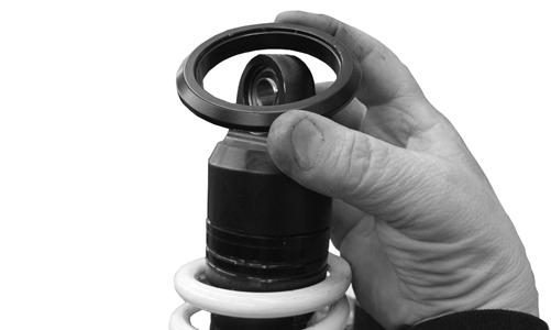
4.Remove the circlip and spring retainer from the shock body.
HDX339
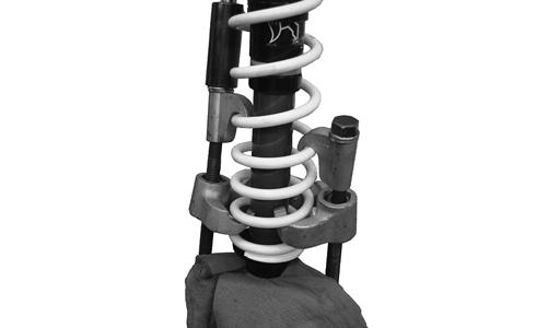
5.Slowly decompress the spring via the shock spring compressors to remove tension from the spring; then remove the spring. CLEANING AND INSPECTING 1.Clean all shock absorber components in parts-cleaning solvent. 2.Inspect each shock rod for nicks, pits, rust, bends, and oily residue. 3.Inspect all springs, spring retainers, shock rods, sleeves, bushings, shock bodies, and eyelets for cracks, leaks, and bends. INSTALLING 1.Place the spring over the shock body and onto the bottom spring retainer. Using readily available shock spring compressors, install the spring compressors onto the spring towards the bottom end of the assembly.
HDX337
2.Compress the spring until approximately one inch of clearance is obtained between the top of the spring and circlip groove in the wear sleeve; then install the top spring retainer, beveled side up.
HDX340
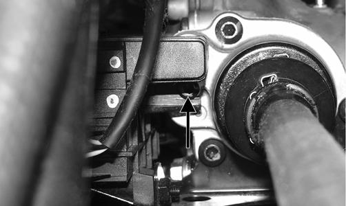
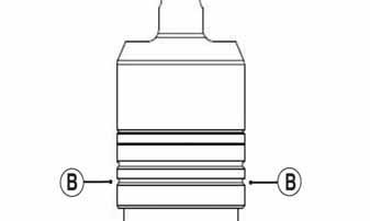
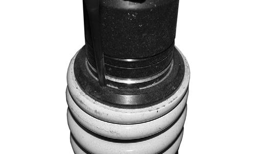
3.Place a new circlip into position (A) on the wear sleeve.
VOR-059B
HDX455A
4.Slide the spring retainer up against the circlip; then, using a punch or flat blade screw driver, seat the circlip into the internal recess of the spring retainer. NOTE: Place a piece of duct tape around the outside
diameter of the shock body below the wear sleeve to protect the finish of the shock body.
HDX456
5.Slowly decompress the spring via the shock spring compressors to remove tension from the spring; then remove the spring compressor tool.
Front A-Arms
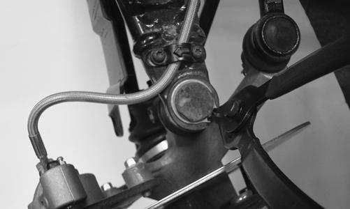
REMOVING 1.Remove the hubs (see Drive System). 2.Remove the brake hose clamp from the upper A-arm; then release the anchors from the A-arm.
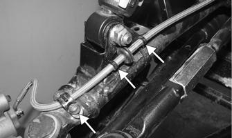
HDX295A
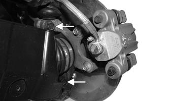
3.Remove the cotter pin and slotted nut securing the tie rod end to the knuckle; then remove the tie rod end from the knuckle. 4.Remove the cap screws securing the ball joints to the knuckle.
CAUTION
Support the knuckle when removing the cap screws or damage to the threads will occur.
PR193
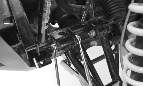
5.Tap the ball joints out of the knuckle; then remove the knuckle. 6.Remove the lower shock absorber eyelet from the upper A-arm.
HDX293
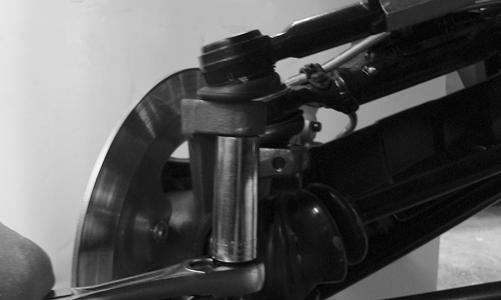
7.Remove the cap screws securing the A-arms to the frame.
HDX296
8.Remove the snap ring from the ball joint; then remove the ball joint from the A-arm.
HDX297
CLEANING AND INSPECTING 1.Clean all A-arm components in parts-cleaning solvent. 2.Clean the ball joint mounting hole of all residual
Loctite, grease, oil, or dirt for installing purposes. 3.Inspect the A-arm for bends, cracks, and worn bushings. 4.Inspect the ball joint mounting holes for cracks or damage. 5.Inspect the frame mounts for signs of damage, wear, or weldment damage. INSTALLING 1.Apply Loctite Primer “T” to the A-arm socket; then apply green Loctite #609 to the entire outside diameter of the ball joint. Install the ball joint into the Aarm and secure with the snap ring. 2.Install the A-arm assemblies into the frame mounts and secure with the cap screws. Only finger-tighten at this time.
HDX296
3.Route the brake hose along the upper A-arm. Secure with hose anchors and the clamp.
HDX295A
4.Secure the lower eyelet of the shock absorber to the lower A-arm. Tighten nut to 42 ft-lb. 5.Secure the A-arm assemblies to the frame mounts (from step 2). Tighten the upper A-arm cap screws to 47 ft-lb and the lower A-arm cap screws to 42 ft-lb. 6.Install the knuckle assembly onto the ball joints and secure with cap screws. Tighten to 35 ft-lb.
HDX386A
7.Install the tie rod end and secure with the nut (coated with red Loctite #271). Tighten to 30 ft-lb; then install a new cotter pin and spread the pin to secure the nut.
NOTE: During assembly, new cotter pins should be
installed.
HDX387
8.Apply grease to the hub and drive axle splines; then install the hub (see Drive System).
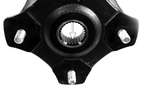
PR290A
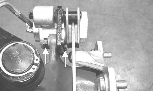
9.Secure the brake caliper holder to the knuckle with two new “patch-lock” cap screws. Tighten to 20 ftlb.
PR377B
10. Install the wheels and using a crisscross pattern, tighten the wheel nuts in 20 ft-lb increments to a final torque of 40 ft-lb (steel wheel), 60 ft-lb (aluminum wheel w/black nuts), or 80 ft-lb (aluminum wheel w/ chrome nuts). 11.Remove the vehicle from the support stand.
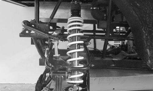
REMOVING 1.With the vehicle in park, secure the vehicle on a support stand to elevate the wheels.
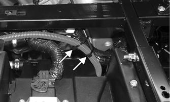
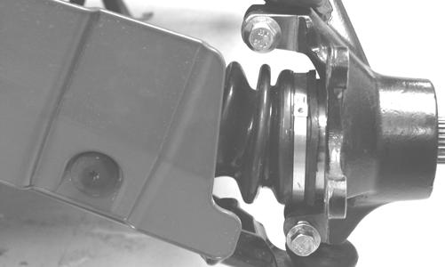
2.Remove the wheel. 3.Secure a strap to the top of the rear knuckle and frame. This will support the knuckle and axle while the A-arms are being removed. 4.Remove the cap screws securing the boot guard to the lower A-arm. 5.Loosen and remove the sway bar link lock nut and cap screw. Account for bushings, washers, and spacer. ! WARNING
Make sure the vehicle is solidly supported on the support stand to avoid injury.
PR922
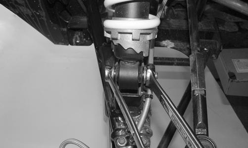
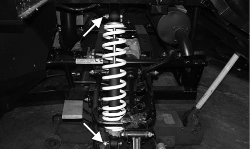
6.Remove the cap screws and lock nuts securing the shock absorber to the frame and lower A-arm; then remove the shock absorber. Discard the lock nuts.
500
PR923A
HDX294
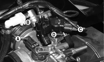
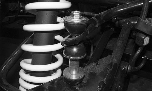
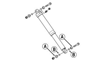
7.On the 700, note the installed locations of the spacers (A) and O-rings (B) on both top and bottom sides of the shock assembly.
HDX547A
8.Remove the cap screws and lock nuts securing the lower A-arm to the frame and knuckle; then remove the lower A-arm. Follow the same procedure to remove the upper A-arm. CLEANING AND INSPECTING 1.Clean all A-arm components in parts-cleaning solvent. 2.Inspect the A-arm for bends, cracks, and worn bushings. 3.Inspect the frame mounts for signs of damage, wear, or weldment damage. INSTALLING 1.Install the A-arm assemblies into the frame mounts and secure with the cap screws and new lock nuts.
Finger-tighten only at this time. 2.Slide the knuckle onto the drive axle and into position on the A-arms; then secure the knuckle to the Aarms with cap screws and new lock nuts. Tighten to 42 ft-lb. 3.Tighten the hardware securing the A-arms to the frame mounts (from step 1) to 42 ft-lb. 4.Secure the shock absorber to the frame with a cap screw and new lock nut. On the 700, place an O-ring onto each spacer; then insert into the shock eyelet.
Tighten to 35 ft-lb. 5.Secure the shock absorber to the lower A-arm with a cap screw and new lock nut. On the 700, place an Oring onto each spacer; then insert into the shock eyelet. Tighten to 42 ft-lb. 6.Install the sway bar link and tighten to show three full threads. 7.Secure the boot guard to the lower A-arm with the two cap screws. Tighten securely. 8.Install the wheels and using a crisscross pattern, tighten the wheel nuts in 20 ft-lb increments to a final torque of 40 ft-lb (steel wheel), 60 ft-lb (aluminum wheel w/black nuts), or 80 ft-lb (aluminum wheel w/chrome nuts). 9.Remove the vehicle from the support stand.
Wheels and Tires
TIRE SIZE
! WARNING
Use only Arctic Cat approved tires when replacing tires. Failure to do so could result in unstable vehicle operation.
This vehicle is equipped with low-pressure tubeless tires of the size and type listed in the General Information section. Do not under any circumstances substitute tires of a different type or size.
TIRE INFLATION PRESSURE Front and rear tire inflation pressure with passenger should be 82.7 kPa (12 psi) cold. Front and rear tire inflation pressure with passenger and cargo should be 137 kPa (20 psi) cold. REMOVING 1.Secure the vehicle on a support stand to elevate the wheels.
2.Remove the nuts securing the wheels; then remove the wheels. CLEANING AND INSPECTING 1.Clean the wheels and hubs with parts-cleaning solvent. 2.Clean the tires with soap and water. 3.Inspect each wheel for cracks, dents, or bends. 4.Inspect each tire for cuts, wear, missing lugs, and leaks. ! WARNING
Always use the size and type of tires specified. Always maintain proper tire inflation pressure.
! WARNING
Do not mix tire tread patterns. Use the same pattern type on front and rear. Failure to heed warning could cause poor handling qualities of the vehicle and could cause excessive drive train damage not covered by warranty.
! WARNING
Make sure the vehicle is solidly supported on the support stand to avoid injury.
INSTALLING 1.Install each wheel on its hub and secure with the existing hardware.
2. Using a crisscross pattern, tighten the wheel nuts in 20 ft-lb increments to a final torque of 40 ft-lb (steel wheel), 60 ft-lb (aluminum wheel w/black nuts), or 80 ft-lb (aluminum wheel w/chrome nuts). CHECKING/INFLATING 1.Using an air pressure gauge, measure the air pressure in each tire. Adjust the air pressure as necessary to meet the recommended inflation pressure. 2.Inspect the tires for damage, wear, or punctures. ! WARNING
Do not operate the vehicle if tire damage exists.
NOTE: If repair is needed, follow the instructions
found on the tire repair kit or remove the wheel and have it repaired professionally.
NOTE: Be sure all tires are the specified size and
have identical tread pattern.
Troubleshooting
Problem: Suspension too soft Condition Remedy
1. Spring preload incorrect 1.Adjust preload 2. Spring(s) weak 2.Replace spring(s) 3. Shock absorber damaged 3.Replace shock absorber 4. Rear shock absorbers too soft 4.Check and adjust air pressure in shocks
Problem: Suspension too stiff Condition Remedy
1. Spring preload incorrect 1.Adjust preload 2. A-arm-related bushings worn 2.Replace bushing
Problem: Suspension noisy Condition Remedy
1. Cap screws (suspension system) loose 1.Tighten cap screws 2. A-arm-related bushings worn 2.Replace bushings
Problem: Vehicle pulling or steering erratic Condition Remedy
1. Vehicle steering is erratic on dry, level surface 1.Check front wheel alignment and adjust if necessary (see Steering/Body/Controls - Front Wheel Alignment) 2. Vehicle pulls left or right on dry, level surface 2.Check air pressure in tires and adjust to specifications