58 minute read
Fuel Systems

This section has been organized for servicing the fuel systems; however, some components may vary from model to model. The technician should use discretion and sound judgment when removing/disassembling and assembling/installing components. Whenever any maintenance or inspection is made on the fuel system where fuel leakage may occur, there should be no welding, smoking, or open flames in the area.
WARNING
Since the fuel supply hose may be under pressure, remove it slowly to release the pressure. Place an absorbent towel around the connection to absorb gasoline; then remove the hose slowly to release the pressure. Always wear safety glasses when removing the fuel hoses.
NOTE: Whenever a part is worn excessively,
cracked, or damaged in any way, replacement is necessary.
SPECIAL TOOLS A number of special tools must be available to the technician when servicing the fuel systems. NOTE: When indicated for use, each special tool
will be identified by its specific name, as shown in the chart below, and capitalized.
Description p/n
EFI Analyzer 0744-049 EFI Diagnostic System Manual 2257-850 EFI Diagnostic System Manual (Instructions) 2259-020 Fluke Model 77 Multimeter 0644-559 Fuel Hose Clamp Tool 0644-545 Fuel Pressure Test Kit 0644-587 Vacuum Test Pump 0644-131 Fuel Pump Installation Tool Kit 0744-074 Laptop Diagnostic Test Kit 0744-050 Laptop Diagnostic Tool 0744-060 Main Jet Wrench 0644-065 Oil Injection Usage Tool 0644-007
NOTE: Special tools are available from the Arctic
Cat Service Parts Department.
Fuel System (Carbureted)
PRE-MAINTENANCE CHECKS 1.Remove the in-line fuel filter. If the filter is dirty, replace the filter. NOTE: Determine which style in-line fuel filter is
being replaced and remove and install accordingly.
2.Install a new filter making sure the arrow on the filter is directed toward the fuel pump.
728-272B
3.Check the hoses to ensure that all are correctly connected; then check for cracks. If any cracks are evident in the hoses, replace them making sure none are against any hot or moving parts. Hoses must fit tightly. If hoses do not fit tightly, cut 6 mm (1/4 in.) from the end and install. 4.Check the impulse hose for cracks or any possible air leaks. The hose must fit tightly at both ends. If loose or cracked, replace the hose. 5.Check each carburetor vent hose for kinks or obstructions; remove any obstructions. 6.Check each carburetor float chamber drain hose for water or debris. If seen, clean by removing the plug and draining the drain hose into a small container. 7.Check the gas tank vent hose and fuel hose for obstructions; remove any obstructions.
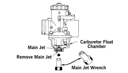
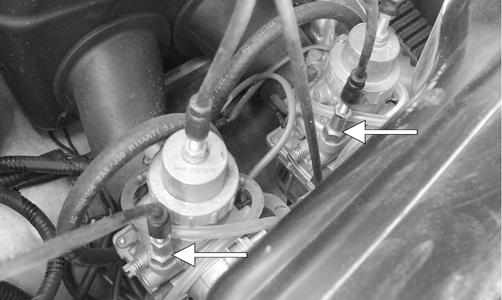
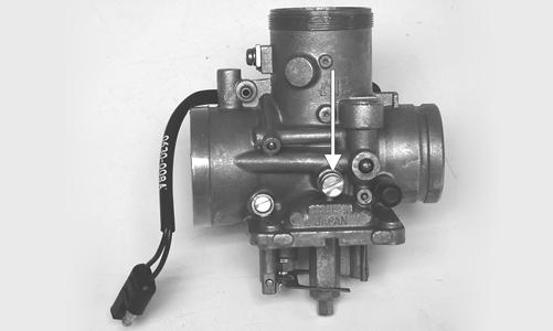
Changing Main Jets
1.Loosen each carburetor flange clamp and remove each carburetor from the intake flange and boot. 2.Remove the drain plug and O-ring from each carburetor float chamber and drain the gas into either a small container or an absorbent towel. 3.Using Main Jet Wrench, thread the main jet out of each carburetor. Account for the baffle ring. Install the new main jet with baffle ring and tighten securely. 4.Install the drain plug and O-ring; then tighten securely.
CAUTION
When installing the carburetors, make sure the gasline hoses are properly routed to avoid premature wear and/or contact with exhaust components.
0728-054
5.Install and secure each carburetor.
Carburetor
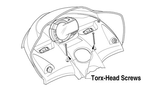
REMOVING 1.Remove the hood and left-side access panel; then remove the torx-head screws securing the console.

0743-777
2.Lift the rear of the console and disconnect the console/main harness plug-in; then remove the console. 3.Disconnect the safety switch wiring harness connector from the main wiring harness; then remove the brass choke-cable housing from the carburetor.
TZ103A TZ104A
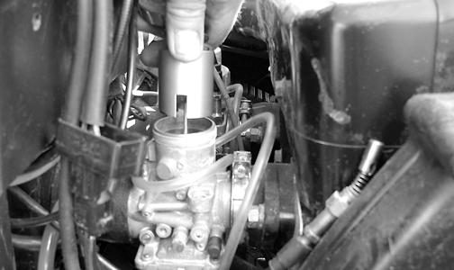
4.Loosen the carburetor-flange clamp; then remove the carburetor.
TZ102A
NOTE: Slide the carburetor into the air silencer boot until free of the flange; then remove carburetor.
CAUTION
Keep MAG-side and PTO-side carburetors identified for installing purposes.
5.Remove the clamp and disconnect the fuel hose from the carburetor inlet fitting; then loosen the lock plate screw and remove the lock plate from the mixing body top.
AH284D
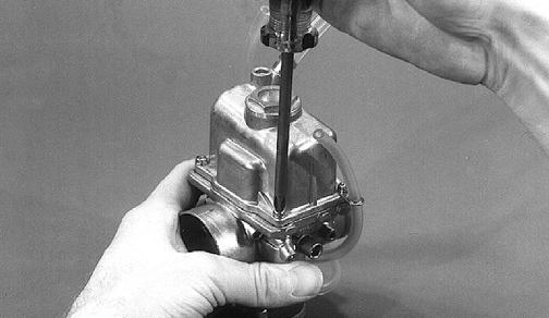
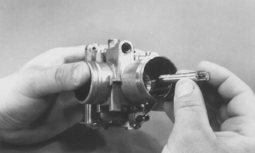
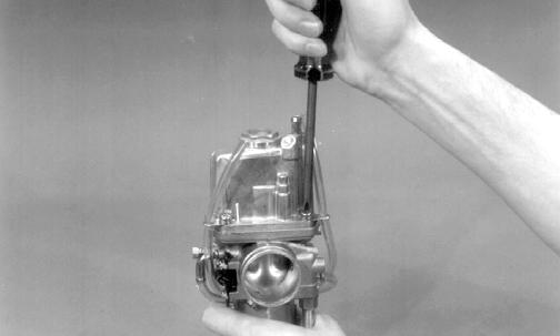
6.Remove the mixing body top by rotating it counterclockwise; then remove the top with spring and piston valve assembly from the carburetor.
NOTE: The floats should be removed only if
replacement is necessary or the float chamber requires cleaning with carburetor cleaner.
2.Remove the caps from the float towers; then remove the floats. Remove the drain screw and O-ring.
CM047
DISASSEMBLING
VM-34
KEY 1.Mixing Body Assy 2.Starter Plunger Cap 3.Starter Plunger Spring 4.Starter Plunger 5.Spring 6.Idle Speed Screw 7.Spring 8.Pilot Air Screw 9.Pilot Jet 10.Baffle Ring 11.Main Jet 12.Mixing Body Top 13.Piston Valve Spring 14.Plate 15.Magnet Block 16.Screw w/Washer 17.E-Clip 18.Washer 19.Jet Needle 20.Piston Valve 21.Needle Jet 22.Self-Tapping
Screw 23.Magnetic Switch 24.Plate 25.Screw w/Spring
Washer 26.Washer 27.Needle Valve
Assy 28.Float Pin 29.Float Arm 30.Cap 31.Float 32.Gasket 33.Float Chamber 34.Plate 35.Hose 36.Screw w/Spring
Washer 37.O-Ring 38.Drain Screw 39.Cap 40.Washer
0738-474
NOTE: Unless a problem with the safety switches
exists, do not loosen or remove the screws securing the switch to the carburetor.
1.Remove the four screws and lock washers securing the float chamber; then remove the float chamber and gasket.
B344
3.Remove the float arm pin; then remove the float arm.
CAUTION
Use care when removing the float arm pin or the towers may break. Also, the pin must be removed from its flattened side.
CM050A
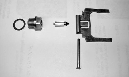
4.Remove the needle valve and the seat. Account for a washer from the seat.
CM051
5.Remove the main jet and baffle ring; then remove the main jet extender guide from the needle jet. Push the needle jet out through the top of the carburetor.
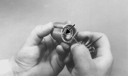
AH084
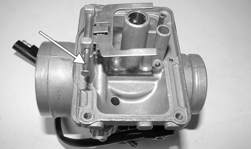
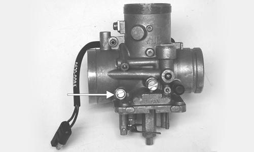
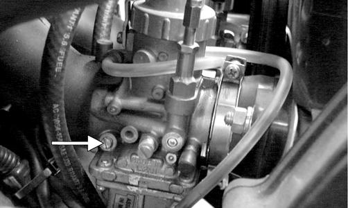
6.Remove the pilot jet.
CM052
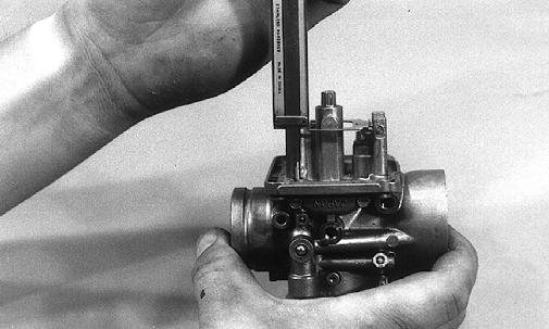
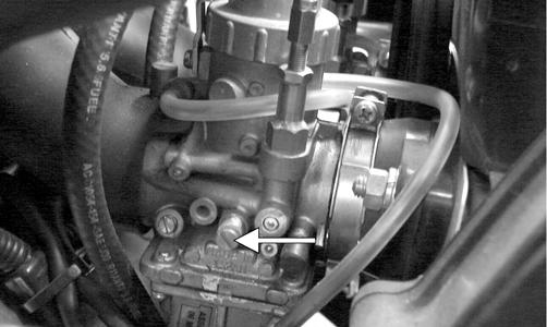
7.While counting the rotations for installing purposes, rotate the pilot air screw clockwise until lightly seated; then remove the pilot air screw and spring.
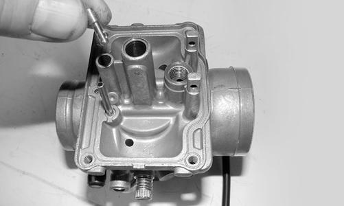
CM053A
8.Remove the idle speed screw and spring.
CM053B
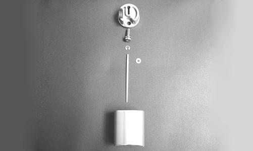
9.Remove the Phillips-head screw securing the throttle cable retainer to the piston valve; then remove the retainer. Account for the jet needle with E-clip and washer.
AH074A
CM054
NOTE: Note the position of the E-clip on the jet nee-
dle for assembly purposes.
CAUTION
If an engine problem has been experienced due to improper gas/air mixture, verify the carburetor jetting and E-clip position with the Specification Chart and Carburetor Jet Chart on the snowmobile for altitude, temperature, and type of gasoline.
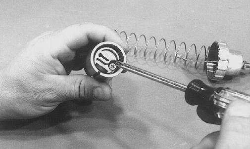
10.Separate the starter plunger assembly from the choke cable by compressing the spring and removing the plunger from the cable; then remove the spring.
Thread the plunger cap off the cable. CLEANING
1.Place all metallic components in a wire basket and submerge in carburetor cleaner. 2.Soak for approximately 30 minutes; then rinse with fresh parts-cleaning solvent. 3.Wash all non-metallic components with soap and water. Rinse thoroughly. 4.Dry all components with compressed air only making sure all holes, orifices, and channels are unobstructed. CAUTION
DO NOT place any non-metallic components in parts-cleaning solvent or carburetor cleaner because damage or deterioration will result.
INSPECTING 1.Inspect the mixing body for cracks, nicks, stripped threads, and any other imperfections in the casting. 2.Inspect the piston/throttle valve for cracks, score marks, or imperfections in the casting. 3.Inspect the condition of the piston valve spring. 4.Inspect the float for perforations or damage. 5.Inspect the gaskets, O-rings, and washers for distortion, tears, or noticeable damage. 6.When applicable, inspect the tips of the idle speed screw, jet needle, pilot air screw, needle valve, and fuel mixture screw for wear, damage, or distortion. NOTE: When inspecting the inlet needle, inspect the
side guides and tip for wear. If the guides show any sign of wear, replace the inlet needle.
7.Inspect the pilot jet and main jet for obstructions or damage. 8.Inspect the starter plunger and seat for wear or damage. 9.Inspect the carburetor mounting flanges for damage and tightness.
ASSEMBLING 1.Install the idle speed screw and spring.
! WARNING
Always wear safety glasses when drying components with compressed air.
CAUTION
DO NOT use wire or small drill bits to clean carburetor orifices, holes, or channels. Distorted or damaged orifices, holes, or channels can result in poor carburetor operation.
CAUTION
An air leak between the carburetor and engine will cause a lean condition and severe engine damage will result.
CM053B
2.Install the pilot air screw and spring. Rotate clockwise until lightly seated; then turn counterclockwise the same number of turns as noted in disassembling for an initial setting.
CM053A
CAUTION
DO NOT force the pilot air screw when seating. Forcing the screw will result in damage to the carburetor body.
3.Install the pilot jet.
CM052
4.Insert the needle jet into position from the top of the carburetor making sure the groove in the needle jet is aligned with the pin in the mixing body; then place the jet extender, baffle ring, and main jet into position and secure.
AH084
5.In order, place a washer and inlet seat into position and secure. Install the inlet needle valve.
CM051
6.Place the float arm into position and secure with the pin.
CM050A
7.Check the float arm height. Using a calipers, measure the distance from the gasket surface to the top of the float arm (with the carburetor inverted). If measurement is not within 22-24 mm, adjust by bending the actuating tab.
B344
9.Place the gasket and float chamber into position and secure with the four screws and lock washers making sure the hose plates are properly positioned on the two front screws. Install the vent hoses.
AH137
10.Place the E-clip into position on the jet needle. From the bottom of the jet needle, slide the E-clip washer up against the E-clip. Place the jet needle into the piston valve. NOTE: Place the E-clip in the proper position as
noted in disassembly.
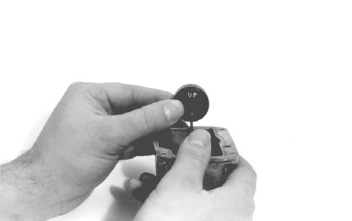
AH046
8.Place the O-ring and drain plug into position and secure; then place the floats into position making sure the word UP is properly positioned. Press the caps onto the float towers.
725-266C
11.Place the cable retainer into the piston valve and secure with the Phillips-head screw. Guide the cable end down into the cable retainer slot and slide the cable end to the center of the piston valve. Release the spring and retainer plate to lock the cable in position.
AH075
NOTE: The round part of the cable end must come
through the hole in the plate/piston valve. If it doesn’t, the cable isn’t assembled to the piston valve correctly.
12.Thread the plunger cap onto the choke cable. Place the spring over the cable end and compress. Position the cable end into the starter plunger and release the spring. INSTALLING 1.Place the piston valve into position making sure the full-length groove in the piston valve is aligned with the pin in the mixing chamber bore; then thread the mixing body top onto the carburetor and tighten securely.
CM056A
NOTE: Prior to threading the mixing body top onto
the carburetor, assure the rubber washer is positioned correctly on the body top.
2.Making sure the mixing body top plate is properly positioned, secure the mixing body top by tightening the screw and lock washer. 3.Connect the fuel hose to the carburetor inlet fitting; then using Fuel Hose Clamp Tool, secure the hoses to the carburetor with the clamps. 4.Place the carburetor into position in the flange and air silencer boot; then tighten the flange clamp making sure the carburetor is level. Do not over-tighten the flange clamp as it will damage the carburetor flange.
TZ102A
NOTE: Slide the carburetor into the air silencer
boot; then slide the carburetor into the flange.
CAUTION
When installing the carburetors, make sure the gasline hoses are properly routed to avoid premature wear and/or contact with exhaust components.
5.Thread the brass choke-cable housing into the carburetor making sure the washer is properly positioned and tighten securely.
TZ104A
6.Connect the safety switch harness connectors to the main wiring harness. 7.Adjust the carburetors to the initial setting (see
ADJUSTING in this sub-section). 8.Place the console into position on the headlight support bracket (do not secure the console with the torx-head screws at this time); then connect the console/main harness plug-in. 9.With the belt guard secured, start the engine and warm up to operating temperature; then adjust the carburetors (if necessary) until proper calibration is attained.
10.Secure the console to the steering support with the torx-head screws and tighten the screws securely; then close the left-side access panel and close the hood. CAUTION
Never run the engine with the hood harness disconnected or damage to the electrical system will result.
The air silencer and boots must be in position whenever the engine is run. If the silencer is removed and the engine is run, a lean condition will result. Therefore, DO NOT run the engine when the air silencer is removed.
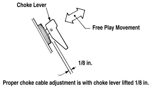
Choke Cables 1.Be sure the ignition switch key is in the OFF position and the brake lever lock is set. 2.Loosen the jam nut securing the choke cable adjuster. Rotate the choke cable adjuster clockwise until it bottoms against the brass plunger cap. 3.Slowly rotate the choke cable adjuster counterclockwise while checking the choke lever for free-play. As soon as all free-play has been removed from the end of the lever, stop rotating the adjuster. 4.With free-play removed from the lever, slowly rotate the choke cable adjuster once again clockwise while checking the choke cable lever for free-play. Adjust until 1/8 in. free-play between front bottom edge of lever and housing is attained. Securely tighten the adjuster jam nut.
0732-848
5.Repeat steps 3 and 4 on each carburetor. NOTE: If a carburetor choke cable is adjusted too
tight, the engine will only operate on 1 cylinder at idle.
Piston Valves NOTE: The air silencer is a one-piece unit, and the
silencer boots can be removed to access the intake bores. Remove the boots from the carburetor to access the piston valves.
1.Rotate each idle speed screw counterclockwise until all spring tension is removed. 2.Loosen the jam nut securing each throttle cable swivel adapter; then rotate the swivel adapter clockwise until the piston valve bottoms in the piston valve bore. 3.In turn on each carburetor, place a finger lightly against the side of the piston valve; then rotate the carburetor swivel adapter counterclockwise until slight upward movement of the valve is noted. 4.In turn on each carburetor, place a finger against either piston valve. Rotate the idle speed screw clockwise until it contacts the valve.
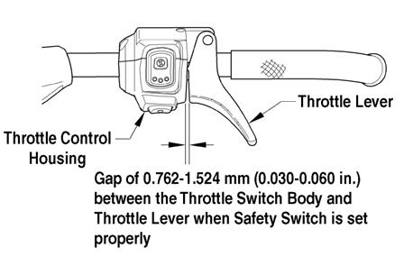
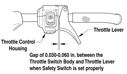
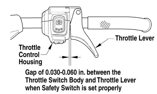
5.Compress the throttle lever to the full-open position; then rotate each idle speed screw clockwise 2 complete turns. Release the throttle lever. NOTE: The throttle control is equipped with a
3-prong emergency stop switch connector. There must be free-play between the lever and the control housing.
741-518A
NOTE: If cable free-play gap is incorrect, rotate
each swivel adapter an equal amount until recommended free-play is achieved. Each piston valve must be resting against the tip of its idle speed screw.
NOTE: If throttle cable free-play is incorrect, the
carburetor safety switches will be activated prematurely and the engine will not start.
6.Install the air silencer boots making sure they are properly seated to the carburetor. Synchronizing Piston Valves NOTE: Arctic Cat recommends using a suitable car-
buretor synchronizer. If a carburetor synchronizer is not available, use the following procedure.
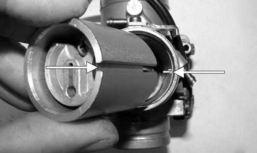
1.Move the air silencer boots off the intake bores of the carburetors. 2.Check to make sure the piston valves start to open at the exact same moment by placing a thumb and finger against the valves; then lightly compress the throttle lever. 3.With slight pressure being applied to the throttle lever, the piston valves should start to open at the exact same time. Compress and release the throttle lever several times to assure accurate determination of piston valve opening. 4.If a piston valve starts to open before another, rotate the swivel adapter on the valve which is lifting first clockwise, just enough to synchronize the valves. NOTE: Recheck by repeating steps 2-4. 5.Tighten the swivel adapter jam nuts securely. Slide the rubber throttle cable caps down over the swivel adapters. NOTE: There must be free-play in the throttle lever. ! WARNING
Be sure to tighten the swivel adapter jam nuts securely. If a swivel adapter jam nut is not tightened, the adjuster can rotate out of the carburetor cap causing the piston valve not to return to the full-closed position.
6.After synchronization has been attained, install the air silencer boots over the intake bores of the carburetors. Pilot Air Screws 1.While counting the rotations, carefully rotate each pilot air screw clockwise until lightly seated.
TZ107A
CAUTION
Do not force a pilot air screw when rotating it clockwise; damage to the pilot air screw needle tip will result.
2.Rotate each pilot air screw counterclockwise the same number of turns as noted in step 1 for an initial setting. 3.Synchronize the oil-injection pump (see Oil-Injection Pump (2000) in this section). Engine Idle Speed 1.With the snowmobile on a shielded safety stand, start the engine, release the brake lever lock, and thoroughly warm up. Fine-tune each idle speed screw and each pilot air screw until the engine idles smoothly at the desired RPM (1500 RPM is recommended). NOTE: Make engine idle adjustment only after the
engine has reached running temperature. Since the idle speed screws have not been adjusted, apply slight throttle pressure to keep the engine running. Allow engine to warm up for 2-3 minutes.
2.After the engine has been allowed to warm up for 2-3 minutes, adjust engine idle by first rotating the
PTO-side carburetor idle speed screw clockwise until the tachometer reads 1480 RPM. 3.Rotate the MAG-side carburetor idle speed screw clockwise until tachometer reads 1500 RPM. 4.Rotate the PTO-side carburetor idle speed screw clockwise until the tachometer reads slightly above 1500
RPM; then rotate the idle speed screw counterclockwise to achieve exact 1500 RPM reading. The piston valves should now be synchronized and the engine should idle without holding any throttle pressure. NOTE: If the engine has no ignition spark with the
throttle in the idle position but has proper spark with the throttle lever slightly compressed, the carburetor safety switches must be repositioned.
5.Test the throttle control lever by compressing and releasing it several times. The lever must return to the idle position quickly and completely. ! WARNING
DO NOT operate the snowmobile when any component in the throttle system is damaged, frayed, kinked, worn, or improperly adjusted. If the snowmobile is operated when the throttle system is not functioning properly, personal injury could result.
Throttle Cable
REMOVING 1.Loosen the throttle cable adjuster jam nuts. 2.Remove the mixing body tops. 3.Remove the throttle cables from the piston valves. 4.Remove the throttle cables from the mixing body tops. 5.Remove the handlebar pad and console. 6.Remove the throttle cable end from the throttle lever. 7.Remove the cable from the throttle switch assembly. NOTE: It may be necessary to remove the PTO-side
carburetor.
8.Remove the E-ring securing the oil-injection cable to the control arm. Account for a washer. 9.Loosen the jam nut securing the adjustment cable; then remove the cable from the oil-injection pump. INSTALLING 1.Route the throttle cable from the throttle switch assembly to the carburetors and oil-injection pump; avoid any sharp bends or moving parts. 2.Install the oil-injection adjustment cable on the oil-injection pump; secure with the jam nuts. 3.Install the oil-injection cable on the control arm; secure with a washer and E-ring. NOTE: Install the PTO-side carburetor if removed.
4.Install the throttle cable into the throttle switch assembly making sure it snaps into place. 5.Install the throttle cable end on the throttle lever. 6.Install the handlebar pad and console.
7.Attach the throttle cable to each throttle valve. The valve must seat in the groove of the throttle cable end; then thread the throttle cable into each mixing body top. 8.Install each piston valve and mixing body top on the carburetors. Tighten securely; then secure the tops to the carburetors with the plates. 9.Adjust the carburetors (see Carburetor - ADJUST-
ING TPS in this section).
CAUTION
Compress the throttle control lever to ensure free movement. If the throttle cable sticks or binds, correct the problem before starting the engine.
10.Synchronize the oil-injection pump (see Oil-Injection Pump (2000) in this section).
Choke Cable
REMOVING 1.Bend down the lock tabs locking each brass choke cable housing on each carburetor. 2.Using a 12-mm wrench, remove each brass choke cable housing from each carburetor. Account for the lock tab washers. 3.Remove each brass plunger and spring from the cable end; then remove each brass choke cable housing. 4.Remove the screws securing the console. 5.Position the choke lever in the middle-choke position; then remove the knurled nut securing the choke lever housing to the console.
725-001A
6.Slide the choke lever housing from the console. 7.Cut any cable ties used to secure the choke cable and remove the choke cable from the engine compartment.
INSTALLING 1.Position the choke lever in the middle-choke position; then from the back side of the console, insert the choke lever housing through the console. Secure with the knurled nut. 2.Route the choke cable from the console to each carburetor; avoid any sharp bends or moving parts. 3.Install each brass choke cable housing onto the cable end; then install each spring and brass plunger. 4.Place the lock tab washer on each brass housing and insert a choke plunger into each carburetor. 5.Thread each brass choke cable housing into each carburetor and tighten. Bend the lock tab up to secure the brass housing. Adjust the choke cable (see
Carburetor- ADJUSTING TPS in this section). 6.Place the console into position and secure with the screws.
Fuel Pump
PRELIMINARY CHECKS NOTE: Make sure adequate gasoline exists in the
gas tank, all hoses are clear and free of kinks and obstructions, the fuel filter is not plugged or damaged, fuel and impulse hoses are in good condition, and evidence of good impulse exists at the crankcase impulse fitting.
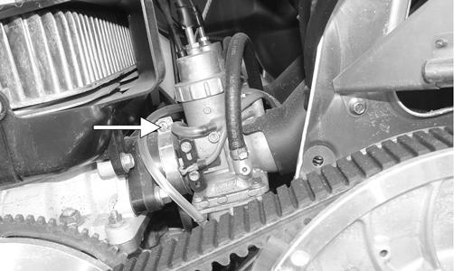
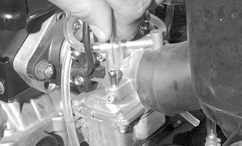
TESTING PRESSURE 1.Connect Fuel Pressure Test Kit between fuel pump and carburetor using a piece of fuel hose and a T-fitting. 2.Place snowmobile on a safety stand and start the engine. The specified pressures must be as indicated.
1000-2000 RPM 3.0-3.5 psi 3000-4000 RPM 4.5-5.5 psi 5000-6000 RPM 6.0-7.0 psi
3.Remove gauge and hose and connect fuel hose to carburetor. TESTING VACUUM NOTE: Make sure adequate fuel is in the carburetor
for this test.
1.Connect Vacuum Test Pump directly to the fuel pump inlet fitting. 2.With snowmobile on a safety stand, start the engine and accelerate to 2000-3000 RPM for 30 seconds.
Note maximum reading of gauge. Reading must be 7-10 in.-hg. 3.Stop engine. Connect fuel hose. Turn the shut-off valve to the OPEN position.
Troubleshooting
Problem: Carburetor Too Rich (0-1/4 Opening) Condition Remedy
1. Choke plunger will not seat 1.Adjust - service - replace choke cable - plunger assembly 2. Pilot air screw too far in 2.Adjust pilot air screw 3. Pilot air passage obstructed - damaged 3.Remove obstruction - replace pilot air screw - carburetor 4. Float/inlet needle obstructed - damaged - adjusted incor- 4.Remove obstruction - replace inlet needle - float - adjust float rectly tab 5. Pilot jet loose 5.Tighten pilot jet
Problem: Carburetor Too Rich (1/4-3/4 Opening) Condition Remedy
1. Pilot air screw too far in 1.Adjust pilot air screw 2. Needle jet needle worn - adjusted incorrectly - incorrect 2.Replace needle jet - replace - adjust jet needle E-clip 3. Pilot air passage obstructed - damaged 3.Remove obstruction - replace pilot air screw - carburetor 4. Pilot jet loose 4.Tighten pilot jet 5. Float/inlet needle obstructed - damaged - adjusted incor- 5.Remove obstruction - replace inlet needle - float - adjust float rectly tab 6. Main jet loose - too large 6.Tighten - replace main jet 7. Primary air passage obstructed 7.Remove obstruction
Problem: Carburetor Too Rich (3/4-WOT Opening) Condition Remedy
1. Main jet loose - too large 1.Tighten - replace with smaller main jet 2. Float/inlet needle obstructed - damaged - adjusted incor- 2.Remove obstruction - replace inlet needle - float - adjust float rectly tab 3. Needle jet needle worn - adjusted incorrectly - incorrect 3.Replace needle jet - replace - adjust jet needle E-clip
Problem: Carburetor Too Lean (0-1/4 Opening) Condition Remedy
1. Choke plunger remains seated 1.Adjust - service choke cable - plunger assembly 2. Pilot air screw too far out - damaged 2.Adjust - replace pilot air screw 3. Piston valve sticks open - damaged - worn 3.Service - replace piston valve - throttle cable - spring 4. Pilot jet - outlet obstructed 4.Remove obstruction 5. Float/inlet needle obstructed - damaged - adjusted incor- 5.Remove obstruction - replace inlet needle - float - adjust float rectly tab
Problem: Carburetor Too Lean (1/4-3/4 Opening) Condition
Remedy
1. Pilot air screw too far out - damaged 2. Needle jet obstructed 3. Pilot jet - outlet - main jet obstructed 4. Float/inlet needle obstructed - damaged - adjusted incorrectly 5. Jet needle E-clip position incorrect 1.Adjust - replace pilot air screw 2.Remove obstruction 3.Remove obstruction 4.Remove obstruction - replace inlet needle - float - adjust float tab 5.Adjust E-clip
Problem: Carburetor Too Lean (3/4-WOT Opening) Condition Remedy
1. Main jet obstructed - too small 1.Remove obstruction - replace with larger main jet 2. Float/inlet needle obstructed - damaged - adjusted incor- 2.Remove obstruction - replace inlet needle - float - adjust float rectly tab 3. Needle jet needle obstructed 3.Remove obstruction
Problem: General Fuel System (Engine Cuts Out at High RPM) Condition Remedy
1. Fuel delivery inadequate 1.Repair - replace fuel pump - impulse hose 2. In-line fuel filter obstructed - damaged 2.Remove obstruction - replace in-line fuel filter 3. Gasoline contaminated 3.Replace gasoline - de-ice - clean carburetors 4. Gas-tank vent - hose obstructed 4.Remove obstruction - replace vent - hose
Problem: General Fuel System (One Cylinder Runs Lean) Condition Remedy
1. Carburetor-to-cylinder air leak 1.Repair/replace gaskets/flanges - service intake ports tighten clamps 2. Carburetors not aligned vertically 2.Align carburetors vertically 3. Primary compression (crankcase) low 3.Troubleshoot engine 4. Carburetors not synchronized 4.Synchronize carburetors
Fuel System (EFI)
INTRODUCTION The Arctic Cat EFI System operates off a series of coils located on the stator and is made up of the following components. 1.An engine control module (ECM) calculates input from sensors (air temperature sensor, coolant temperature sensor, and throttle position sensor). To provide the engine with the correct fuel mixture and timing for optimum operation. 2.Charge coils (1 and 2), located on the stator, provide
AC voltage to the ECM/CCU where AC voltage is converted to DC voltage. 3.A fuel pump coil located on the stator operates the low voltage, high output fuel pump. At cranking speed, the high output fuel pump provides enough fuel to charge the fuel rail. 4.An injector coil located on the stator provides the injectors with DC voltage for operation through the
ECM. 5.A lighting coil located on the stator plate provides output to the CCU to operate accessories and the lighting system. FLOODED ENGINE If the engine should become flooded, set the brake lever lock, compress the throttle lever to the full-open position, and crank the engine over until it starts and clears itself. Release the brake lever lock. FUEL SYSTEM The fuel is first drawn into the electric fuel pump through multiple pick-up valves and hoses. The fuel is then routed through a high-pressure fuel hose to the fuel rail. The fuel pressure is maintained in the fuel rail by the fuel regulator. With the fuel pressure maintained at a constant psi, the ECM evaluates the information it receives from the electrical sensors and opens the injectors for precise periods of time (pulse widths) to meet engine demands. NOTE: The entire EFI system depends on all coils
functioning properly on the stator.
Individual Components
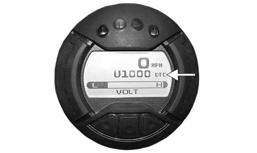
ECM The ECM is the brain of the EFI system. It uses sensor inputs to determine the correct fuel/air ratio for the engine given the existing conditions of altitude and temperature. If any of the sensors should fail while the engine is running, the ECM will sense a problem and go into a “fail safe” mode. This is an over-rich condition and will greatly reduce performance. However, the engine will be protected from a possible lean condition and engine damage. The ECM is equipped with a self-diagnostic system utilizing the service icon in the speedometer/tachometer and remains illuminated when a problem exists with any of the sensors. The technician can determine the problem sensor by reading the code shown on the readout screen and applying it to the ECM Diagnostic Codes chart (see Self-Diagnostic System/Codes in this section). NOTE: The ECM cannot be repaired. Removing (3000) 1.Remove both access panels; then remove the hood. 2.Remove the air intake assembly from the throttle body and the radiator. 3.Press the retaining tab on the ECM connector in; then rotate the connector arm up while will allow the connector to be released from the ECM. 4.Remove the four cap screws and nuts securing the
ECM to the chassis. Installing (3000) 1.Secure the ECM to the chassis using the existing four nuts. Tighten securely; then press the connector into the ECM and rotate the connector arm down until it locks. NOTE: Make sure all connectors are clean and
tight. Apply dielectric grease to all connector seals.
2.Install the air intake assembly to the throttle body and the radiator. 3.Install the hood and access panels. Removing (7000) 1.Open the hood. 2.Remove the four screws and nuts securing the ECM to the right-side skid plate. 3.Press the retaining tabs on the ECM connectors in; then rotate the connector arms up while will allow the connectors to be released from the ECM. Installing (7000) 1.Secure the ECM to the right-side skid plate using the existing four screws and nuts. Tighten securely; then press the two connectors into the ECM and rotate the connector arm down until it locks. NOTE: Make sure all connectors are clean and
tight. Apply dielectric grease to all connector seals.
2.Close and latch the hood. AIR TEMPERATURE SENSOR This sensor detects air temperature entering the air silencer and engine. The ECM sends current to this sensor, and (depending on the temperature) the sensor will pass a certain amount of current through the sensor to ground. The ECM measures how much current passes through the sensor to ground. From this measurement, the ECM determines the air temperature and calculates the fuel/air mixture ratio. Resistance will drop as the temperature rises.
Removing 1.Disconnect the wiring harness from the air temperature sensor. 2.Using a flat-blade screwdriver, pry the sensor end to end to remove it from the air silencer. Account for two push pins. Installing 1.Place the sensor into position in the air silencer and secure with push pins. 2.Connect the wiring harness to the air temperature sensor. Secure the sensor wires with cable ties so they do not rub on any other components. COOLANT TEMPERATURE SENSOR This sensor detects coolant temperature. The ECM measures the current flow through the sensor to ground. From this measurement, the ECM can determine the engine coolant temperature and calculate the correct fuel/air mixture ratio. NOTE: If the coolant temp rises above 105°C
(221°F) the temp light on the gauge will start to flash and the engine will go into a fuel cut (surging) mode to alert the rider of overheating. If the temp continues to rise and exceeds 110°C (230°F) the temp light will be on continuously. The fuel cut will not protect the engine from overheating if the operator continues to ride the snowmobile.
THROTTLE POSITION SENSOR This sensor is a potentiometer (essentially, a resistor). This sensor transforms the throttle-valve position into output voltage to the ECM. In addition, the sensor detects the opening or closing speed of the throttle valve and feeds that rate of voltage change to the ECM. NOTE: The input from the throttle position sensor
is one of the main inputs for the ECM calculation of fuel/air mixture ratio.
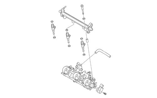
FUEL INJECTORS A fuel injector is an electromagnetic injection valve controlled by a signal from the ECM. The coil used in the injector is a high-pressure resistance type. The ECM determines the optimum fuel injection time and duration based on signals from the sensors. When voltage is sent to the fuel injector, it energizes the coil and opens the needle valve, thereby injecting fuel. Because the fuel pressure (pressure differential between fuel line and manifold) is kept constant, the amount of fuel injected is determined by the duration of time the valve is open and manifold pressure. Removing (3000) WARNING
Since the fuel supply hose may be under pressure, remove it slowly to release the pressure. Place an absorbent towel around the connection to absorb gasoline; then remove the hose slowly to release the pressure. Always wear safety glasses when removing the fuel hoses.
1.Disconnect the gasline connector from the fuel rail.
XM430A
2.Disconnect the wiring harness from each injector. 3.Remove the cap screws securing the fuel rail to the intake manifold; then remove the rail from the injectors. 4.Remove the fuel injectors from the throttle body assembly. Account for four grommets.
Installing (3000) 1.Apply a light coat of oil to all four grommets; then install onto each injector. 2.Install the injectors into the intake manifold. 3.Place the fuel rail into position on top of the injectors and secure with existing cap screws. 4.Connect the gasline to the fuel rail. 5.Connect the wiring harness to the injectors. Cable tie as needed.
Removing (7000) WARNING
Since the fuel supply hose may be under pressure, remove it slowly to release the pressure. Place an absorbent towel around the connection to absorb gasoline; then remove the hose slowly to release the pressure. Always wear safety glasses when removing the fuel hoses.
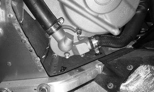
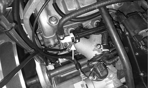
1.Remove the orange clamp securing the fuel supply hose to the fuel rail. 2.Disconnect the wiring harness from each injector. 3.Remove the cap screws and washers securing the fuel rail to the throttle body assembly; then remove the rail from the injectors. Account for two washers and two spacers.
SNO-369
4.Remove the fuel injectors from the throttle body assembly. Account for six grommets. Installing (7000) 1.Apply a light coat of oil to all six grommets; then install onto each injector. 2.Install the injectors into the throttle body assembly. 3.Place the fuel rail into position on top of the injectors and secure with existing spacers, washers and cap screws.
SNO-369
4.Connect the fuel delivery hose to the fuel rail and secure with the orange clamp. 5.Connect the wiring harness to the injectors. Cable tie as needed. FUEL PRESSURE REGULATOR The fuel pressure regulator maintains the fuel pressure at a constant specified level. EXHAUST AIR TEMPERATURE (EAT) SENSOR This platinum, thin-film sensor detects the exhaust air temperature in the exhaust system. The ECM sends current to this sensor, and (depending on the temperature) the sensor will pass a portion of that current to ground. The ECM measures how much current passes through the sensor to ground. From this measurement, the ECM determines the exhaust air temperature and adjusts the fuel, ignition timing, and APV calibration. Resistance will increase as the temperature rises.
CRANKSHAFT POSITION SENSOR This sensor measures the location in degrees of rotation of the crankshaft. A 15° resolution exists between signals. The signal is triggered by teeth on the outer surface of the flywheel as they pass by the sensor. The sensor gives the ECM the location of the crankshaft at a given point in time. The ECM processes the information and uses it in many different types of calculations. For example, the sensor can be used for RPM, and it can also be used to determine the rate of acceleration of the crankshaft. CAMSHAFT POSITION SENSOR This sensor tells the ECM which stroke the engine is on. Because the 5000 engine operates on a 720° cycle, the piston is at TDC twice per cycle - once on the exhaust stroke and once on the compression stroke. MANIFOLD ABSOLUTE PRESSURE (MAP) SENSOR This sensor measures pressure in the intake manifold when the engine is running. The ECM uses this sensor to aid in calculating the required fueling. After a given throttle opening is reached, the ECM switches to the TPS sensor for its main fuel map. The ECM uses the MAP sensor for many other calculations, but the base fuel map is the main one.
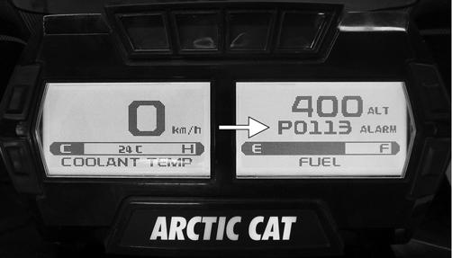
Self-Diagnostic System/Codes
Diagnostic codes are activated by the ECM and may be displayed on the readout screen for a number of reasons. If a code is displayed while the engine is running, the ECM is receiving input that is outside of its established parameters.
XM-273B
If a code has been activated, take the snowmobile to an authorized Arctic Cat Snowmobile dealer for service. If not under warranty, this service is at the discretion and expense of the snowmobile owner. 3000/7000
P1693 Forward Relay Circuit High P1694 Headlight Relay Open P1695 Headlight Relay Low P1780 Shift Switch Stuck P2228 Barometric Pressure Sensor A Circuit Low Code Trouble P2229 Barometric Pressure Sensor A Circuit High P0016 Crankshaft Position - P2282 Air leak between throttle body and intake valves Camshaft Position Correlation P2300 Ignition Coil “A” Primary Control P0030 O2 Heater Control Circuit Circuit Low P0031 O2 Heater Control Circuit Low P2301 Ignition Coil “A” Primary Control P0032 O2 Heater Control Circuit High Circuit High P0107 Manifold Absolute Pressure Circuit Low P2303 Ignition Coil “B” Primary control circuit Low P0108 Manifold Absolute Pressure Circuit High P2304 Ignition Coil “B” Primary Control Circuit High P0112 Intake Air Temperature Sensor P2306 Ignition Coil “C” Primary Control Circuit Low Circuit Low P2307 Ignition Coil “C” Primary Control Circuit High P0113 Intake Air Temperature Sensor P2531 Ignition Switch Run Position Circuit Low Circuit High P2532 Ignition Switch Run Position Circuit Hight P0114 Intake Air Temperature Sensor Circuit Intermittent P0115 Engine coolant temp sensor 1 circuit P0117 Engine Coolant Temperature Sensor 1 Circuit Low U0155 Lost communication with the ECM U1000 Vehicle not registered or invalid PIN U1001 Vehicle not registered and vehicle limits enabled P0118 Engine Coolant Temperature Sensor 1 Circuit High P0119 Engine Coolant Temperature Sensor 1 Circuit Intermittent P0120 Throttle position sensor circuit P0121 Throttle Position Sensor Circuit Range Performance P0122 Throttle Position Sensor Circuit Low P0123 Throttle Position Sensor Circuit High P0130 O2 Sensor Circuit P0131 O2 Sensor Circuit Low Voltage P0132 O2 Sensor Circuit High Voltage P0171 System Too Lean P0172 System Too Rich P0201 Injector Circuit/Open - Cylinder 1 P0202 Injector Circuit/Open - Cylinder 2 P0203 Injector circuit/open - cylinder 3 P0217 Engine coolant over temp condition P0261 Cylinder 1 Injector Circuit Low P0262 Cylinder 1 Injector Circuit High P0264 Cylinder 2 Injector Circuit Low P0265 Cylinder 2 Injector Circuit High P0267 Cylinder 3 injector circuit low P0268 Cylinder 3 injector circuit high P0340 Camshaft Position Sensor “A” Circuit P0500 Vehicle Speed Sensor “A” P0508 Idle Air Control System Circuit Low P0509 Idle Air Control System Circuit High P0511 Idle air control circuit P0522 Engine oil pressure sensor circuit low P0523 Engine oil pressure sensor circuit high P0562 System Relay Voltage Low P0563 System Relay Voltage High P0642 Sensor Reference Voltage “A” Circuit Low P0643 Sensor Reference Voltage “A” Circuit High P0780 Shift Error P1315 Crankshaft Position Out of Sync P1338 Crankshaft Spike Detected P1339 Crankshaft Tooth Number Detection Error P1685 Main Relay Open Circuit P1686 Main Relay Circuit Low P1687 Main Relay Circuit High P1688 Reverse Relay Open Circuit P1689 Reverse Relay Circuit Low P1690 Reverse Relay Circuit High P1691 Forward Relay Open Circuit P1692 Forward Relay Circuit Low
Fuel Pressure Regulator
1.Using the Fuel Pressure Test Kit, connect the tester to the regulator fuel inlet. NOTE: A short piece of 3/8 in. I.D. hose will be
needed to make the above connections.
2.Pressurize the regulator to 28-31.3 psi. Turn the pressure tester shut off valve to the OFF position.
Observe the gauge for several minutes and note any loss of pressure. If pressure begins to drop, the cause may be a ruptured diaphragm, worn spring, or leaking valve. If the regulator fails to build or maintain pressure, replace the regulator. NOTE: If the pressure drops, check the hose con-
nections to ensure no leaks exist.
Throttle Body Assembly
REMOVING/DISASSEMBLING (3000) 1.Remove both access panels, hood, seat, and the gas tank assembly. 2.Loosen the two hose clamps securing the air silencer to the throttle body and the intake tube; then disconnect the ignition coils from the main harness.
Remove the spark plug cap from the engine; then remove the three screws securing the air silencer to the tunnel. Remove the silencer.
XM537
3.Disconnect all connectors from the throttle body assembly; then remove the screw and clamp securing the harness to the throttle body.
XM426
16.Loosen the nut securing the throttle cable; then remove the cable and the throttle body assembly.
XM406
ASSEMBLING/INSTALLING (3000) 1.Install the throttle cable to the throttle body and secure using the existing jam nuts. Tighten securely.
XM406
2.Connect the main harness to both injectors; then connect all other connections on the throttle body and secure the harness using the existing clamp and screw. Tighten securely.
XM404
3.Position the air intake silencer onto the throttle body and the intake tube. Secure using the existing hose clamps. Tighten to 35 in.-lb. 4.Connect main harness to the coils; then connect the coils to the spark plugs making sure to firmly press down the spark plug caps to secure. 5.Secure the air silencer to the tunnel using the three screws. Tighten securely.
XM537
6.Install the gas tank assembly, seat, hood, and both access panels. REMOVING/DISASSEMBLING (7000) NOTE: To remove the throttle body assembly, it is
necessary to open the hood and remove the air silencer.
1.Remove the coolant hoses and MAP sensor hoses from the throttle body. 2.Disconnect the throttle body harness from the main harness; then loosen the three screws securing the throttle body to the intake boots.
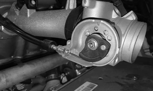
YM-044A
3.Loosen the throttle cable jam nut; then remove the throttle cable from the bracket and the throttle valve cam. Remove the throttle body. 4.Remove the cable ties securing the throttle body harness to the fuel rail.
YM-045A
NOTE: For installing purposes, note the location of
all cable ties.
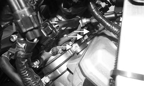
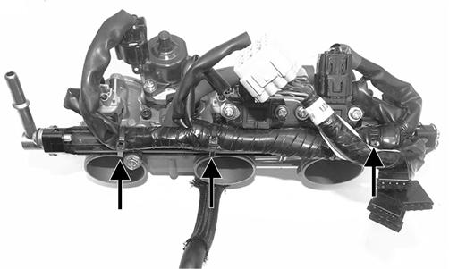
5.Remove the screws and washers securing the fuel rail to the throttle body; then remove the injectors.
Account for six O-rings.

YM-047A YM-048A
NOTE: For assembling purposes, note from which
side the fuel injectors were removed.
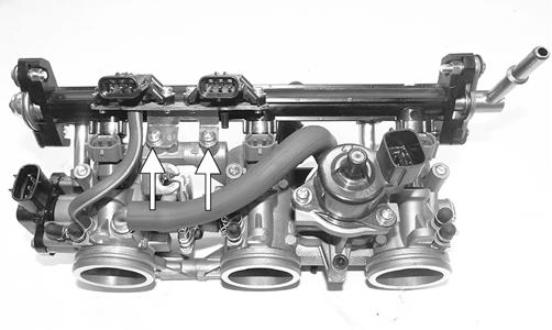
ASSEMBLING/INSTALLING 1.Install the fuel injectors onto the throttle body assembly; then secure the fuel rail and injectors to the throttle body assembly with the four screws, washers and spacers. Tighten securely.
YM-047A
YM-048A
2.Connect all connections of the throttle body harness to the throttle body sensors. Secure the harness to the fuel rail using cable ties.
YM-045A
3.Install the throttle cable to the bracket on the throttle body assembly and to the throttle valve cam; then secure the cable with the jam nut. 4.Install the throttle body assembly to the intake boots and tighten the clamps; then install the coolant hoses and the MAP sensor hoses. Secure the coolant hoses with the clamps.
YM-044A
5.Connect the large gray connector to the main harness. NOTE: To finalize this procedure, install the front
spars, air silencer, hood and both access panels.
Throttle Cable
REMOVING 1.Loosen the throttle cable from the bracket; then remove the throttle cable from the pulley on the throttle body lever shaft. 2.Remove the handlebar pad and console. 3.Remove the cable ties securing the throttle cable. 4.Remove the throttle cable ends from the throttle lever and from the throttle control housing. INSTALLING/ADJUSTING 1.Install the throttle cable into the throttle control assembly making sure the cable snaps into place. 2.Install the throttle cable end on the throttle lever. 3.Route the throttle cable from the throttle control assembly to the throttle body assembly and oil-injection pump; avoid any sharp bends or moving components. 4.Attach the throttle cable to the pulley on the throttle body shaft. 5.Install the handlebar pad and console. 6.Secure the throttle cable to the handlebar and steering post with cable ties. 7.Adjust the throttle cable tension by turning the jam nuts in the appropriate direction until 0.030-0.060 in. free-play exists in the throttle lever and the butterfly completely opens and closes. Tighten the jam nuts securely.
741-518A
CAUTION
Compress the throttle control lever to ensure free movement. If the throttle cable sticks or binds, correct the problem before starting the engine.
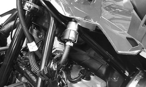
Fuel Filter (7000)
REMOVING Arctic Cat recommends that the in-line fuel filter be replaced every 5000 miles. The in-line fuel filter is located under the hood and on the clutch side of the steering post. The filter must be clean to allow the fuel hose to transmit the amount of gasoline required. If the in-line fuel filter is obstructed, gasoline flow will be restricted; therefore, the filter must be replaced. To remove and install the in-line fuel filter, use the following procedure:
! WARNING
Since the fuel supply hose may be under pressure, always wear safety glasses; then remove the hose slowly to release the pressure. Place an absorbent towel around the connection to absorb the fuel.
NOTE: Before removing the fuel filter, take note of
the filter inlet and outlet for installing purposes.
XM303
1.Remove the fuel filter from the fuel filter bracket. 2.Remove and discard the existing hose clamps; then slowly remove the fuel hoses from the fuel filter.
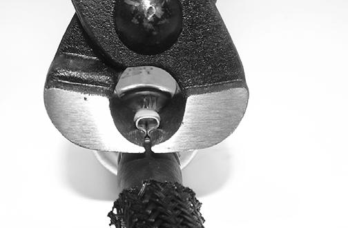
Dispose of the excess fuel from the filter properly. 3.Inspect the fuel hoses thoroughly for any signs of cracking, cuts, or wear points. 4.Place new hose clamps on the gasline hoses; then press the hoses fully onto the fuel filter making sure the inlet and outlet oriented correctly. 5.When installing the new hose clamps make sure there is no more than 9 mm between the filter and the clamps. Secure the new hose clamps using Fuel Hose
Clamp Tool (p/n 0644-545) to make sure the clamps are tight by crimping the clamps until the two clamp areas touch.
SNO-1308
6. Install fuel filter to the fuel filter bracket; then start the engine and inspect the fuel hoses and filter for any signs of leaks.
Fuel Pump
2000 TESTING 1.Remove the hardware securing the console to the gas tank and chassis; then move the console out of the way. 2.Disconnect the gasline hose connector from the fuel pump.
Since the fuel supply hose may be under pressure, remove it slowly to release the pressure. Place an absorbent towel around the connection to absorb gasoline; then remove the hose slowly to release the pressure. Always wear safety glasses when removing the fuel hoses.
3.Connect Fuel Pressure Test Kit to the fuel pump and fuel hose. 4.Start the engine. Fuel pressure should be 42.8-47.3 psi. NOTE: If fuel pressure is not as specified, the pump
is defective and must be replaced.
5.Disconnect the fuel pump from the main wiring harness. 6.Connect the positive lead of a 12-volt power supply to the red wire and the negative lead of the 12-volt power supply to the black wire. 7.The pump should operate (it would be heard running). NOTE: If the fuel pump fails to operate, reverse the
power supply at the fuel pump connector allowing the motor to run in the opposite direction. This will verify that nothing has entered and/or obstructed the pump.
NOTE: If the fuel pump still fails to operate, the
pump is defective and must be replaced.
REMOVING 1.Disconnect the fuel level sensor connector. 2.Remove the six self-tapping screws securing the retaining plate; then remove the fuel pump noting the orientation of the fuel pump outlet for installing purposes. Account for the seal. 3.Remove and discard the hose clamp securing the gasline hose to the fuel pump inlet.
WARNING
Since the fuel supply hose may be under pressure, remove it slowly to release the pressure. Place an absorbent towel around the connection to absorb gasoline; then remove the hose slowly to release the pressure. Always wear safety glasses when removing the fuel hoses.
NOTE: If the fuel pickup assembly is not being
replaced, inspect the screens for any tears or obstructions. Also check the gasline hoses and replace if necessary.
INSTALLING 1.Install a new seal on the fuel pump; then with a new hose clamp, secure the gasline hose with the pickup assembly to the inlet of the fuel pump. 2.Install the fuel pump and pickups into the gas tank and position the fuel pump so the outlet is properly oriented (as noted during removing).
4.Connect the fuel level sensor harness connector. 3000 TESTING 1.Remove the seat, remove the torx screws securing the fuel pump protector to the fuel tank assembly.
CAUTION
Use care not to over tighten the retaining plate screws or damage to the gas tank may result.
6.Connect the positive lead of a 12-volt power supply to the red wire and the negative lead of the 12-volt power supply to the black wire. 7.The pump should operate (it would be heard running). NOTE: If the fuel pump fails to operate, reverse the
power supply at the fuel pump connector allowing the motor to run in the opposite direction. This will verify that nothing has entered and/or obstructed the pump.
NOTE: If the fuel pump still fails to operate, the
pump is defective and must be replaced.
REMOVING
CAUTION
Before removing the fuel pump of fuel level sensor from the gas tank, be sure the fuel level is low or fuel may leak from the gas tank.
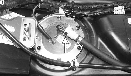
1.Remove the seat(s); then remove the torx screws securing the fuel pump protector to the fuel tank assembly.
YM-086A
3.Disconnect the gasline hose connector hose from the outlet of the fuel pump by pressing inward on the white connector, pressing in the black release, and finally pulling back on the hose.
WARNING
Since the fuel supply hose may be under pressure, remove it slowly to release the pressure. Place an absorbent towel around the connection to absorb gasoline; then remove the hose slowly to release the pressure. Always wear safety glasses when removing the fuel hoses.
YM-086A
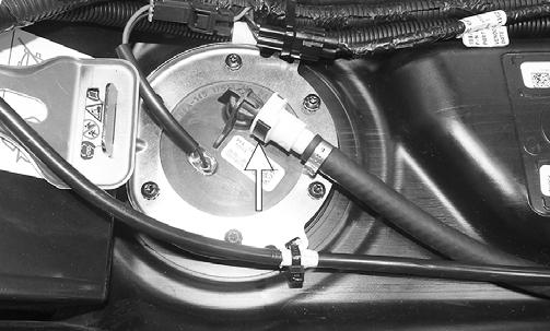
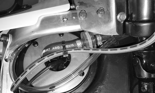
2.Disconnect the fuel pump harness connector; then disconnect the gasline hose from the outlet of the fuel pump by pressing inward on the white connector, pressing in the black release, and finally pulling back on the hose. Remove both cable ties secured to the fuel pump ring.
YM-050A
3.Connect Fuel Pressure Test Kit to the fuel pump and fuel hose. 4.Turn the ignition key to the ON position. Fuel pressure should be approximately 42.8-47.3 psi. NOTE: If fuel pressure is not as specified, the pump
is defective and must be replaced.
5.Disconnect the fuel pump from the main wiring harness.
YM-050A
WARNING
Since the fuel supply hose may be under pressure, remove it slowly to release the pressure. Place an absorbent towel around the connection to absorb gasoline; then remove the hose slowly to release the pressure. Always wear safety glasses when removing the fuel hoses.
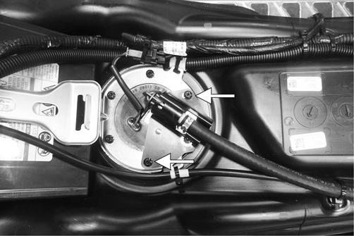
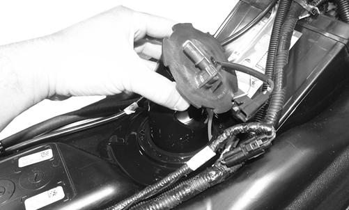
3.Remove and retain the six torx-head screws securing the fuel pump in the fuel tank; then remove the snap ring. 4.Carefully remove the fuel pump and fuel pickup assembly from the gas tank noting the orientation of the fuel pump outlet for assembling purposes.
YM-051
NOTE: If the fuel pickup assembly is not being
replaced, inspect the screens for any tears or obstructions. Also check the hoses and replace if necessary.
INSTALLING 1.The two fuel pickups should be pressed together then carefully slide into the fuel pump opening in the gas tank; then install the fuel pump and orientate it so the fuel hose connection faces the front right of the snowmobile.
YM-051
2.Install the retaining ring over the fuel pump and secure the fuel pump to the gas tank assembly using the existing torx-head screws. Tighten to 40 in.-lb.
3.Connect the fuel pump harness connector to the main harness and secure to the retaining ring with a cable tie; then secure the gasline hose to the fuel pump making sure it locks into place. Secure the cables to the fuel pump ring using two cable ties.
CAUTION
Use care not to over tighten the retaining plate screws or damage to the gas tank may result.
YM-050A
4.Install the fuel pump protector using the existing screws. Tighten to 40 in.-lb.
YM-086A
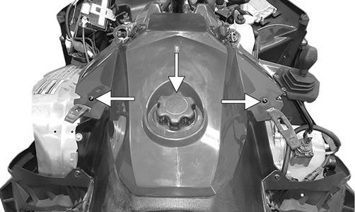
5.Install the seat. 7000 TESTING 1.Open the hood; then remove both access panels.
Remove the screws securing the console.
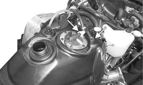
BC258C
3.Disconnect the gasline hose connector hose from the outlet of the fuel pump by pressing inward on the white connector, pressing in the black release, and finally pulling back on the hose.
WARNING
Since the fuel supply hose may be under pressure, remove it slowly to release the pressure. Place an absorbent towel around the connection to absorb gasoline; then remove the hose slowly to release the pressure. Always wear safety glasses when removing the fuel hoses.

BC257B
3.Connect Fuel Pressure Test Kit to the fuel pump and fuel hose. 4.Turn the ignition key to the ON position. Fuel pressure should be approximately 42.8-47.3 psi. NOTE: If fuel pressure is not as specified, the pump
is defective and must be replaced.
5.Disconnect the fuel pump from the main wiring harness. 6.Connect the positive lead of a 12-volt power supply to the red wire and the negative lead of the 12-volt power supply to the black wire. 7.The pump should operate (it would be heard running). NOTE: If the fuel pump fails to operate, reverse the
power supply at the fuel pump connector allowing the motor to run in the opposite direction. This will verify that nothing has entered and/or obstructed the pump.
NOTE: If the fuel pump still fails to operate, the
pump is defective and must be replaced.
REMOVING
CAUTION
Before removing the fuel pump assembly from the gas tank, be sure the fuel level is low or fuel may leak from the gas tank.
1.Open the hood; then remove both access panels. 2.Remove the screws and gas tank cap securing the console.
BC258C
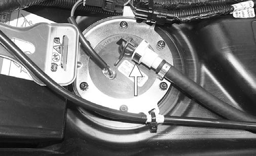
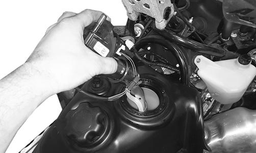
2.Disconnect the fuel pump harness connector; then disconnect the gasline hose from the outlet of the fuel pump by pressing inward on the white connector, pressing in the black release, and finally pulling back on the hose. Remove the cable tie secured to the fuel pump ring.
BC257C
WARNING
Since the fuel supply hose may be under pressure, remove it slowly to release the pressure. Place an absorbent towel around the connection to absorb gasoline; then remove the hose slowly to release the pressure. Always wear safety glasses when removing the fuel hoses.
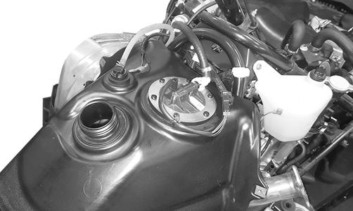
3.Remove and retain the six torx-head screws securing the fuel pump in the fuel tank. 4.Carefully remove the fuel pump and fuel pickup assembly from the gas tank noting the orientation of the fuel pump outlet for assembling purposes.
BC318
NOTE: If the fuel pickup assembly is not being
replaced, inspect the screens for any tears or obstructions. Also check the hoses and replace if necessary.
INSTALLING 1.The two fuel pickups should be pressed together then carefully slide into the fuel pump opening in the gas tank; then install the fuel pump and orientate it so the fuel hose connection faces the front right of the snowmobile.
2.Install the retaining ring over the fuel pump and secure the fuel pump to the gas tank assembly using the existing torx-head screws. Tighten to 40 in.-lb.
3.Connect the fuel pump harness connector to the main harness and secure to the retaining ring with a cable tie; then secure the gasline hose to the fuel pump making sure it locks into place. Secure the cables to the fuel pump ring using a cable tie.
CAUTION
Use care not to over tighten the retaining plate screws or damage to the gas tank may result.
BC257
4.Install the console, gas tank cap, both access panels, and the hood.
Troubleshooting
Problem: Too Rich Condition Remedy
1. Diagnostic trouble code activated 1.Replace problem sensor 2. Fuel pressure too high 2.Replace regulator 3. Fuel return hose obstructed 3.Service - replace hose - remove obstruction 4. Injectors leaking 4.Replace injectors
Problem: Too Lean Condition Remedy
1. Diagnostic trouble code activated 1.Replace problem sensor 2. Fuel pressure too low 2.Replace regulator/fuel pump 3. Vent hose obstructed 3.Remove obstruction 4. Fuel filter(s) obstructed 4.Replace fuel filter(s)
Oil-Injection Pump (2000)
CAUTION
When servicing the oil-injection system, use a 100:1 gas/oil mixture in the gas tank to ensure adequate engine lubrication. Failure to use the 100:1 mixture to the oil-injection system will result in severe engine damage.
REMOVING 1.Remove the carburetors and secure them out of the way in an upright position. 2.Disconnect the oil-supply hose from the pump and plug to prevent oil drainage. 3.Remove the oil-delivery hoses from the adapter plates/intake flanges. 4.Disconnect the oil-injection cable/control rod. 5.Remove the two screws securing the oil-injection pump and retainer to the crankcase; then pull the oil-injection pump away from the retainer/crankcase and account for a gasket/O-ring. NOTE: Remove the oil-injection pump from the
crankcase only if the O-ring or gasket need to be replaced.
6.Turn the pump sideways; then remove the lower union bolt (4). Account for two washer gaskets (1) (3). Remove the pump.
731-551A
7.Remove the remaining union bolts securing the check valves to the pump. Account for the washer gaskets. 8.Remove the check valves. Account for two gaskets. INSTALLING 1.In turn on each front union bolt, install a washer gasket, check valve, and washer gasket; then install on the oil-injection pump. 2.Place the gasket and oil-injection pump near the engine; then install the lower union bolt through a gasket, check valve, and gasket. 3.Position the oil-injection pump on the engine making sure the oil-injection pump gear is correctly aligned with the oil-injection pump drive gear. 4.Secure the pump with two screws (coated with blue
Loctite #243). Tighten screws to 48 in.-lb. 5.Connect the oil-delivery hoses to the adapter plates.
Secure with clamps. 6.Connect the oil-injection cable/control rod to the pump and secure. 7.Connect the oil-supply hose to the oil-injection pump inlet fitting. Secure with the clamp. 8.Bleed the oil-injection system. 9.Check the oil-injection system synchronization (see
SYNCHRONIZING in this sub-section). Tighten the jam nuts securely. 10.Install the carburetors. SYNCHRONIZING
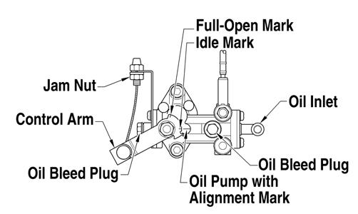
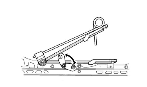
0744-532
1.With the engine off, disconnect the throttle cable from the throttle lever. Pull the throttle cable to the
Full-Open position; then using a suitable clamping device, secure the cable in this position.
2.If the marks are not aligned, adjust synchronization by loosening the jam nut(s) on the adjuster. Rotate the jam nuts/adjuster nut until proper alignment is attained. Tighten jam nut(s). 3.Connect the throttle cable to the throttle lever; then adjust the cable/linkage adjusting nut so the throttle lever moves approximately 1/8 in. before the oil-injection pump control arm begins to move. This ensures the throttle/ignition monitor switch will function properly and prevents ignition “cut-out” and spark plug fouling at low RPM operation
CAUTION
Care must be taken when securing the cable not to kink or damage the cable.
CAUTION
Assure the throttle cable/linkage has returned to the fully closed (idle) position and has not remained partially open and moves freely from the open position to the closed position.
TESTING PUMP NOTE: These tests must be made with the snowmo-
bile and oil at a “room” temperature of 20°-30° C (68°-86° F).
! WARNING
Always wear safety glasses when performing this test.
1.Disconnect the oil pump cable/control rod from the control rod on the pump. 2.Clamp off the oil-supply hose between the oil reservoir and oil pump; then remove the supply hose from the pump. 3.Attach a suitable length of clear oil-supply hose to the oil pump; then using Oil Injection Usage Tool, fill the hose with Arctic Cat Synthetic APV 2-Cycle
Oil. NOTE: Do not fully insert the usage tool into hose.
There must be enough room around the tip of the tool and the hose to allow air in the hose to escape.
4.Fill the tool to the 0 line. 5.Wipe the tip of the tool to remove excess oil; then attach the tool to the oil-supply hose and remove the bulb. 6.Secure the tool to the oil reservoir by twisting the rubber strap one half turn and placing the rubber strap around the tool and the oil reservoir filler neck. NOTE: On the Lynx 2000, the tool can be secured to
the air silencer.
7.With the control rod secured in the Idle position, start the engine and run the engine at 2000 RPM for 3 minutes. Compare the amount of oil used against the specifications listed.
1.4-2.2 cc
Full-Closed (Idle) 3 Minutes
NOTE: Before starting the engine, make sure that
no air is present in the testing equipment.
8.With the control rod secured in the Full-Open position (line-to-line), run the engine at 2000 RPM for 2 minutes. Compare the amount of oil used against the specifications listed.
6.9-9.4 cc
Full-Open 2 Minutes
9.If the oil-injection pump output does not meet the specifications, see TESTING CHECK VALVES in this sub-section. 10.Disconnect the oil usage tool, remove the plug from the reservoir, and attach the oil-supply hose to the oil reservoir. NOTE: After testing the oil pump, the oil pump
must be correctly synchronized with the carburetors/throttle bodies (see SYNCHRONIZING in this sub-section).
TESTING CHECK VALVES If an engine problem occurs due to lack of lubrication, the check valves should be tested using a vacuum pump to make sure they are operating properly. 1.Remove the check valves from the oil-injection pump. 2.Attach the Vacuum Test Pump hose to the check valve. 3.Squeeze the vacuum pump handle and watch the pump gauge. The check valve should release at 4.5-5 lb and again reset itself at 3.5-4 lb. If “release” and
“reset” are not within specifications, replace the check valve. 4.Record the “release” and “reset” readings for the valve; then perform the test on the other valve. The
“release” and “reset” readings must fall within specifications and must be within 1.5 lb of each other. If either or both are not met, replace the check valves. 5.If the check valves are within specifications but oil-injection usage is not, replace the oil-injection pump.
Gas Tank
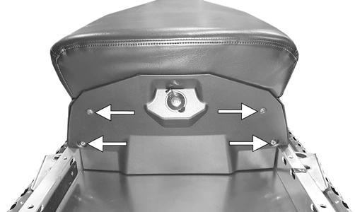
REMOVING (2000) 1.Remove the seat (see Steering and Body section). 2.Remove the four cap screws securing the support tubes to support plate. 3.Remove the six torx-head screws securing the seat support assembly to the tunnel; then slide the support back out of the way.
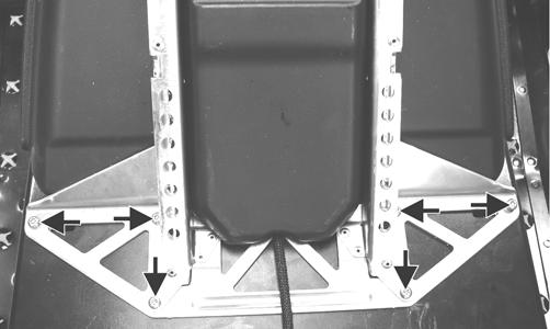
ZJ010A
4.Disconnect the fuel level sensor connector; then slide the gas tank rearward enough to gain access to the gasline hose
5.Remove and discard the clamp securing the gasline to the fuel level sensor; then disconnect the gas tank vent hose and close off the vent hose outlet. Remove the gas tank.
BC301
WARNING
Since the fuel supply hose may be under pressure, remove it slowly to release the pressure. Place an absorbent towel around the connection to absorb gasoline; then remove the hose slowly to release the pressure. Always wear safety glasses when removing the fuel hoses.
INSTALLING (2000) 1.Secure the gasline to the fuel level sensor using a new clamp making sure the clamp is tight; then install the vent hose to the outlet and secure with the hose clamp.
IO054
2.Install the gas tank to its proper position; then secure the tank with the seat support assembly and install the four cap screws securing the seat support tubes to the support plate. Tighten securely. NOTE: It may be necessary to align the U-nut clips
with a punch.
3.Install the six torx-head screws securing the seat support assembly to the tunnel. 4.Connect the fuel level sensor connector.
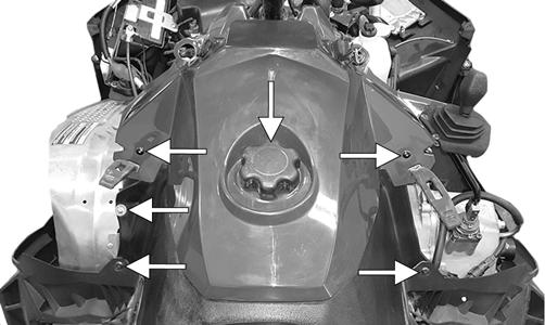
5.Install the seat. 3000 (REMOVING) 1.Remove both access panels and hood. 2.Remove the seat and the lower console. 3.Remove the two machine screws securing the upper console; then disconnect the reverse alarm. 4.Remove and retain all four cap screws securing the rear spar tubes to the chassis and steering support. 8.Remove all battery cables and the battery from the from gas tank. 9.Disconnect the gasline hose, and fuel pump harness.
Remove the gas tank. 3000 (INSTALLING) 1.Install the gas tank; then connect the gasline hose(s), vent hose, and fuel pump harness; then install the battery and connect all battery cables. 2.Connect the reverse alarm; then use the two machine screws to secure the upper console. 3.Install the rear spar tubes and secure using the existing cap screws. Tighten to 23 ft-lb. 4.Install the seat, hood, and both access panels. 7000 (REMOVING) 1.Open the hood and remove both access panels. 2.Lift up the lever on the rear of the seat and hold it in that position; then lift and remove the passenger seat.
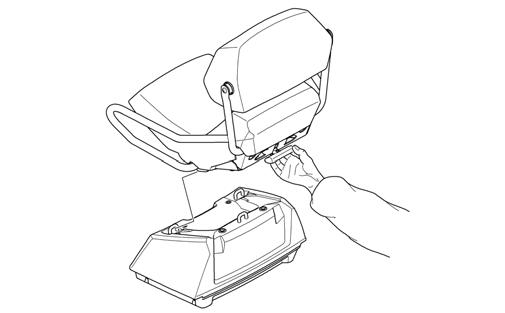
0749-032
3.Open the storage box door; then remove the two shoulder torx screws securing the storage box and remove the storage box. 4.Remove the four self-tapping screws securing the front seat faciafascia to the right- and left-side seat fascia.
BC266A
5.Remove the self-tapping screws, gas tank cap, and gasket securing the console assembly; then disconnect the ignition switch, reverse alarm, and the accessory outlet. Remove the console.
BC258A
WARNING
Since the fuel supply hose may be under pressure, remove it slowly to release the pressure. Place an absorbent towel around the connection to absorb gasoline; then remove the hose slowly to release the pressure. Always wear safety glasses when removing the fuel hose.
6.Remove the gas line vent hose from the check valve; then disconnect the gasline hose connector hose from the outlet of the fuel pump by pressing inward on the white connector, pressing in the black release, and finally pulling back on the hose.
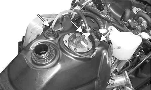
BC257A
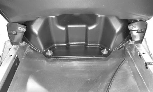
7.Remove the two lock nuts and washers securing the rear of the gas tank assembly to the tunnel. Remove the gas tank making sure to install the gas cap to avoid any fuel from spilling.
BC259
7000 (INSTALLING) 1.Install the gas tank; then connect the gasline hose, vent hose, and fuel pump harness.
BC257A
2.Secure the rear of the gas tank to the tunnel using the existing flat washers and nuts. Tighten securely.
Install the rear fascia using the existing screws. 3.Install the console and connect all wiring connectors; then install the gas tank cap. 4.Install the rear seat(s); then install the access panels and close and latch the hood.