52 minute read
Steering and Body

This section has been organized into sub-sections for servicing steering and body components; however, some components may vary from model to model. The technician should use discretion and sound judgment when removing and installing components. NOTE: Whenever a part is worn excessively,
cracked, or damaged in any way, replacement is necessary.
SPECIAL TOOLS A special tool must be available to the technician when servicing the steering and body systems. NOTE: When indicated for use, each special tool
will be identified by its specific name, as shown in the chart below, and capitalized.
Description p/n
Shock Spring Removal Tool 0644-057 Handlebar Stand 5639-152 Steering Post Stand 5639-946
NOTE: Special tools are available from the Arctic
Cat Service Parts Department.
Steering Post
2000 REMOVING 1.Remove the hood; then remove the two torx-head screws securing the console to the headlight support bracket.
0743-777
2.Lift the rearward end of the console and disconnect the main/hood harness connector; then remove the console. 3.Remove the four cap screws, lock nuts, and adjuster block caps securing the handlebar/riser assembly to the steering post; then lay the handlebar/riser assembly aside. Account for the lower adjuster block. 4.Remove the four cap screws securing the upper bearing bracket to the upper support plate.
FS182A
5.Remove the springs securing the expansion chamber; then remove the expansion chamber from the engine compartment. Account for the rubber exhaust bumper.
FS203A
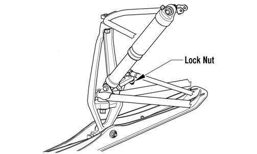
6.Remove and discard the lock nut securing the steering tie rod to the steering post.
ZJ156A
7.Remove and discard the lock nut and washer securing the steering post to the chassis; then carefully guide the steering post out of the chassis.
ZJ157A
NOTE: For installing purposes, note the number of
washers between the steering post and the chassis.
ZJ156B
INSPECTING 1.Inspect all welded areas for cracks or deterioration. 2.Inspect the steering post and steering-post brackets for cracks, bends, or wear. 3.Inspect the bearing halves, bearing caps, and bearing housings for cracks or wear. INSTALLING 1.Carefully install the steering post into the chassis; then with the number of washers installed on the stud of the post as noted during removing, secure the steering post to the chassis with a new lock nut (threads coated with green Loctite #609). Tighten to 35 ft-lb.
ZJ157A
2.Install the steering tie rod to the steering post and secure with new lock nut. Tighten to 35 ft-lb.
ZJ156A
3.Secure the bearing bracket/steering post assembly to the upper support plate with the bracket plates and cap screws (coated with blue Loctite #243). Tighten the cap screws to 96 in.-lb.
FS182A
NOTE: When installing the bracket plates, the
wider end of the plate must be directed up.
FS200A
4.Place the rubber exhaust bumper into position on the air silencer.
FS203A
5.Place gaskets on the resonator and exhaust manifold; then install the expansion chamber. Secure the chamber to manifold and upper frame with the springs. 6.Place the handlebar/adjuster block onto the steering post; then secure the handlebar to the steering post with the adjuster caps, four cap screws, and lock nuts. Tighten cap screws securely. 7.Secure the console to the steering support with the torx-head screws and tighten the screws securely; then close the left-side and right-side access panels and close the hood.
0743-777
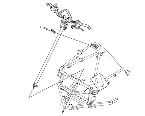
3000 REMOVING 1.Remove the hairpin clip from the pin located at the front of the access panels. Move the panels up and off the pin; then swing the panels all the way out and unhinge the panels from the lower console. 2.Remove all six torx-head screws securing the hood.
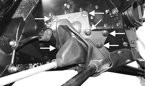
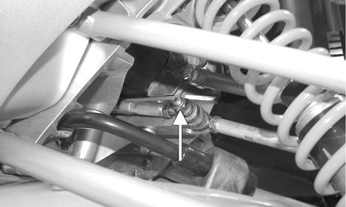
3000 2.Locate the hood harness connector (located under the center vent between the intake vents) and unplug the connector; then move the hood slightly forward and remove the hood. 3.Remove the push rivets securing the right-side steering boot to the chassis. This allows access to the two nuts securing the bottom of the steering post.
XM134A
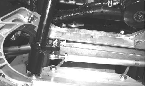
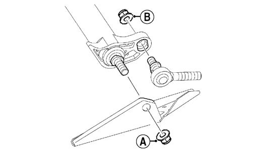
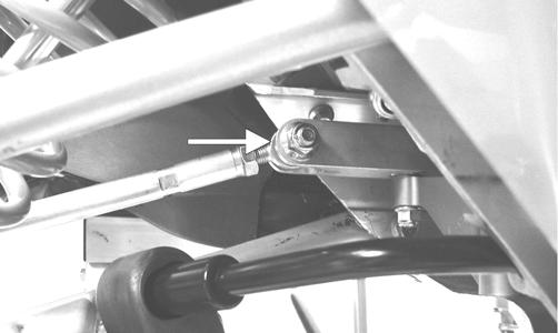
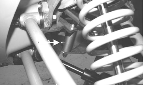
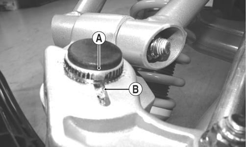
4.Remove the nut (A) securing the bottom of the existing steering post to the steering stop bracket; then remove the nut (B) securing the steering tie rod assembly to the steering post. Discard both nuts.
SNO-2221A
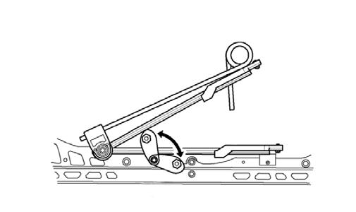
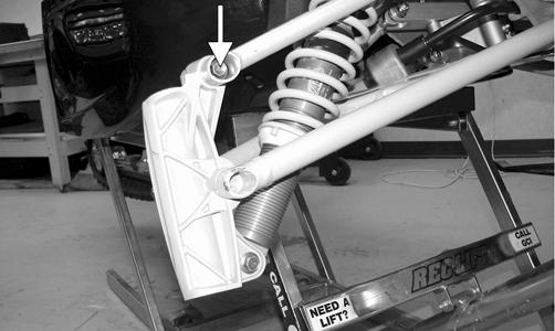
5.Remove the cap screws and handlebar caps securing the handlebar to the top of the handlebar riser; then remove the two torx-head screws and nuts securing the top of steering post to the chassis. Account for both steering post blocks and retaining plate.
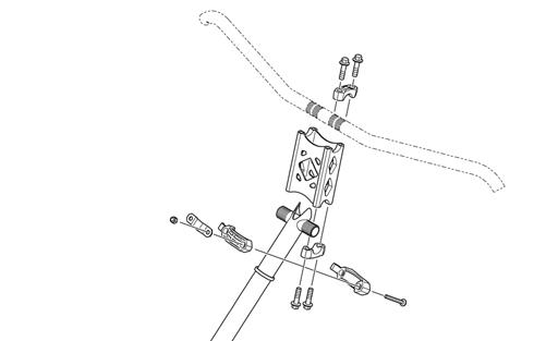
SNO-357
6.Carefully remove the steering post from the snowmobile. INSPECTING 1.Inspect all welded areas for cracks or deterioration.
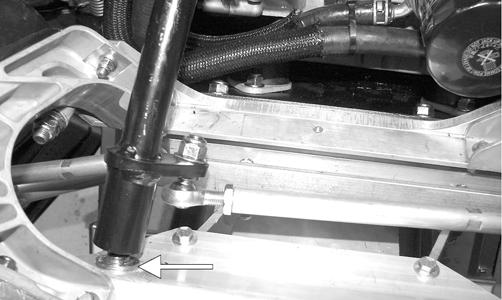
2.Inspect the steering post and steering-post retaining plate for cracks, bends, or wear. 3.Inspect the adjuster caps and mounting block for cracks or wear. INSTALLING 1.Install steering post into position and secure to the steering stop bracket with a new M10 nut. Be sure to
align the steering post ball joint alignment tab
with the steering stop bracket. Tighten to 43 ft-lb.
SNO-2218
2.Secure the tie rod assembly to the steering post using a new M10 nut. Be sure to align the tie rod ball joint alignment tab with the steering post. Tighten to 35 ft-lb.
SNO-2219
3.Secure the right-side steering boot to the chassis using the existing push rivets.
XM134A
4.Secure the top of the steering post to the steering support using the existing retaining plate and nuts.
Tighten to 96 in.-lb. 5.Position the handlebar riser on the steering post and secure using the existing caps and cap screws.
Tighten evenly to 15 ft-lb.
SNO-357
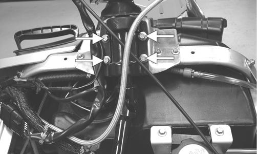
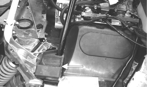
5.Install the expansion chamber using the existing springs; then connect the exhaust temperature sensor to the main harness. 6.Position the hood onto the snowmobile and connect the hood harness connector. 7.Secure the hood with the six torx-head screws and tighten securely. 8.Install the access panels onto the lower console; then close the access panels and secure with the clips. 7000 REMOVING 1.Open the hood and remove both access panels; then disconnect the air temperature sensor connector and the three hoses from the air silencer. Loosen the three hose clamps securing the intake boots to the throttle body. Remove the air silencer and the intake boots.
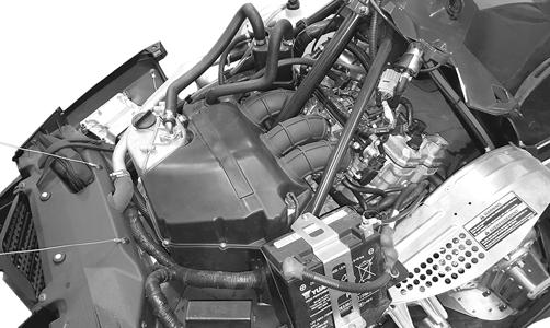
BC245A
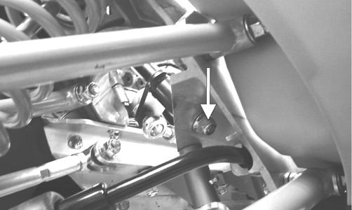
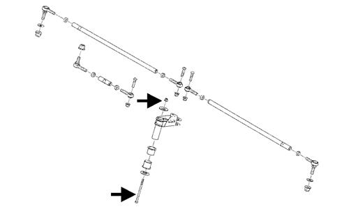
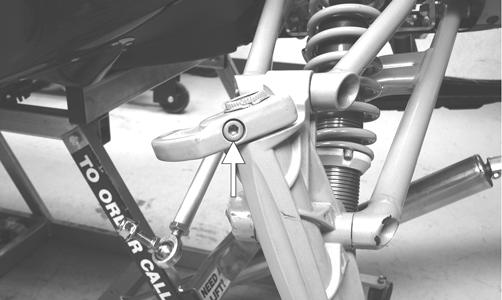
2.Using a 17 mm swivel socket and a ratchet wrench, remove and discard the M10 lock nut w/washer securing the bottom of the steering post to the chassis; then remove the two nuts, retaining plat, and mounting block securing the top of the steering post.
BC251A
3.Remove the cap screws and handlebar caps securing the handlebar to the top of the handlebar riser; then remove the two torx-head screws and nuts securing the top of steering post to the chassis. Account for both steering post blocks and retaining plate.
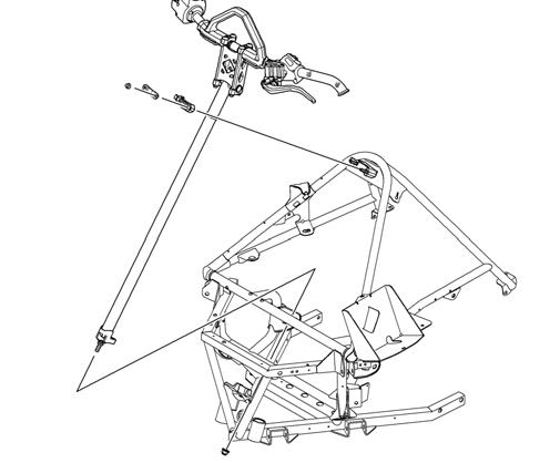
BC251A
2.Secure the top of the steering post to the steering support using the existing mounting block, retaining plate, and nuts. Tighten to 8 ft-lb. 3.Position the handlebar riser on the steering post and secure using the existing caps and cap screws.
Tighten evenly to 15 ft-lb.
SNO-357
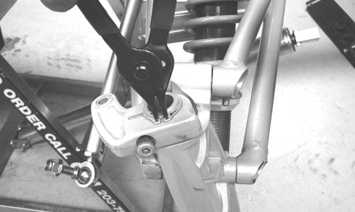
4.Carefully remove the steering post from the snowmobile. INSPECTING 1.Inspect all welded areas for cracks or deterioration. 2.Inspect the steering post and steering-post retaining plate for cracks, bends, or wear. 3.Inspect the adjuster caps and mounting block for cracks or wear. INSTALLING 1.Position the steering post making sure the tab on the steering post is aligned with the groove in the chassis. Secure using new M10 Lock Nut w/Washer.
Tighten to 55 ft-lb.
SNO-357
4.Install the air silencer assembly; then secure the intake boots to the throttle body. Tighten the hose clamps securely. 5.Install the three hoses into the air silencer assembly; then connect the air temperature sensor connector. 6.Close and latch the hood.
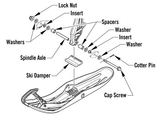
Ski
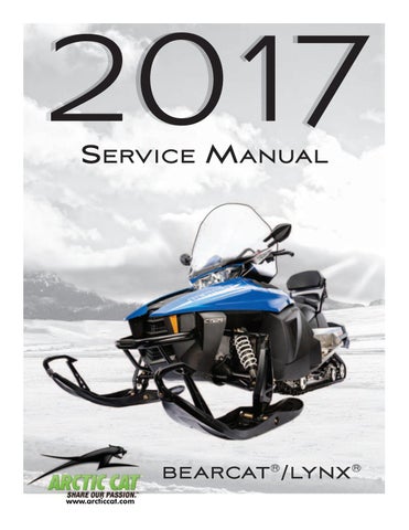
2000 REMOVING 1.Elevate the front of the snowmobile and secure on a support stand. 2.Remove and discard the cotter pin; then remove the nut and cap screw securing the ski to the spindle. 3.Remove the ski. Account for the rubber damper and washers.
INSPECTING 1.Inspect the ski for cracks or deterioration. 2.Inspect the ski for abnormal bends or cracks. 3.Inspect the wear bar for wear. 4.Inspect all hardware and the spindle bushings for wear and damage. 5.Inspect the rubber damper for damage or wear. INSTALLING 1.Slide a washer onto the ski cap screw; then apply all-temperature grease to the cap screw shaft and spindle axle.
0744-526
2.Install the spindle axle into the spindle; then position the ski damper into the bottom of the spindle making sure the higher portion is directed toward the front and press firmly into place. NOTE: The high end of the damper must be posi-
tioned forward.
3.With the cap screw hole of the ski centered with the spindle axle, slide the cap screw with washer through the outside of the ski and spindle assemblies. NOTE: Install the cap screw so the lock nut will be
located to the inside of the ski and the cotter pin slot in the cap screw will be horizontal with the ski.
4.Install the remaining washer and lock nut; then tighten the lock nut to 35 ft-lb. Ensure the cotter pin slot in the cap screw is still horizontal with the ski. 5.Install the cotter pin from the back side of the ski cap screw and spread the pin. 3000/7000 REMOVING 1.Elevate the front of the snowmobile and secure on a support stand. 2.Remove and discard the cotter pin; then remove the nut and cap screw securing the ski to the spindle. 3.Remove the ski. Account for the rubber damper and washers. INSPECTING 1.Inspect the ski for cracks or deterioration. 2.Inspect the ski for abnormal bends or cracks.
3.Inspect the wear bar for wear. 4.Inspect all hardware and the spindle bushings for wear and damage. 5.Inspect the rubber damper for damage or wear. INSTALLING NOTE: Before installing the skis, make sure the car-
bide of the split wear bar will be installed toward the inside of the ski when installed on the snowmobile.
1.Slide a washer onto the ski cap screw; then apply all-temperature grease to the cap screw shaft and spindle axle.
0748-981
2.Install the spindle axle into the spindle; then position the ski damper into the ski grooves making sure the grooved side of the damper is installed rearward. 3.Install the spacers and washers (one on each side of the spindle - standard ski stance, both on the inside of the spindle - minimum ski stance, or both on the outside of the spindle - maximum ski stance) onto the spindle axle. 4.With the cap screw hole of the ski centered with the spindle axle, slide the cap screw with washer through the outside of the ski. NOTE: Local laws and/or regulations as to maxi-
mum width of the ski stance may be applicable. Always comply with the maximum width laws and/or regulations when adjusting ski stance.
NOTE: Install the cap screw so the lock nut will be
located to the inside of the ski and the cotter pin slot in the cap screw will be horizontal with the ski.
5.Install the remaining washers and lock nut; then tighten the lock nut to 35 ft-lb. Ensure the cotter pin slot in the cap screw is still horizontal with the ski. 6.Install the cotter pin from the back side of the ski cap screw and spread the pin. Repeat for opposite ski.
The ski wear bar is a replaceable bar attached to the underside of the ski. If the snowmobile is operated primarily in deep snow, ski wear bar wear will be minimal; however, if the snowmobile is operated on terrain where the snow cover is minimal, the ski wear bar will wear faster. Arctic Cat recommends that the ski wear bars be replaced if worn to 1/2 of original diameter. REMOVING 1.Raise the front of the snowmobile and secure with a suitable stand. 2.Remove the lock nuts securing the wear bar to the ski; then remove the wear bar. INSTALLING 1.Install the wear bar into the ski making sure it is fully seated using a rubber mallet. 2.Secure the wear bar with lock nuts. Tighten to 96 in.-lb.
Drag Link (2000)
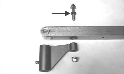
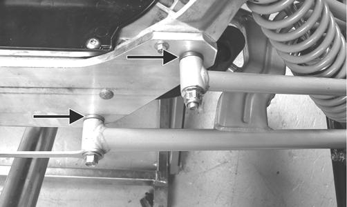
REMOVING 1.Remove the cap screw and lock nut (A) from the drag link end of the inner tie rod; then remove the cap screw and lock nut (B) securing the left-side inner tie rod and steering tie rod to the drag link. Discard the lock nuts.
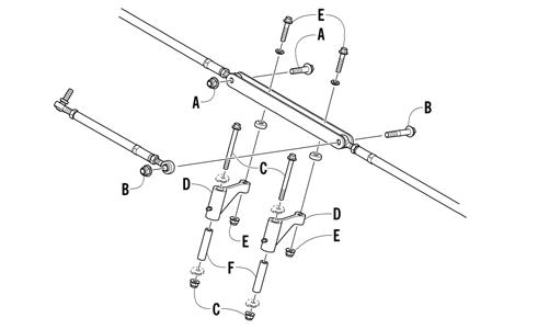
0741-924
NOTE: To aid in removing the tie rod cap screws
from the drag link, position the drag link so the cap screw is aligned with the opening between the skid plate and the suspension mounting bracket.
ZJ159A
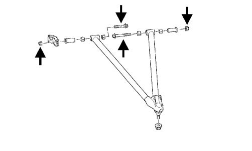
2.Remove the cap screws and lock nuts (C) from the steering arms (D); then remove the drag link and steering arms from the suspension mounting bracket. 3.Secure the drag link in a suitable vise; then remove the cap screws and lock nuts (E) securing the steering arms to the drag link. Remove the arms and account for the axles (F) inside the steering arms. NOTE: With the steering arms removed, note the
direction of the steering arms for installing purposes.
ZJ161A
4.If replacing using a suitable punch, drive the two bearings out of the drag link.
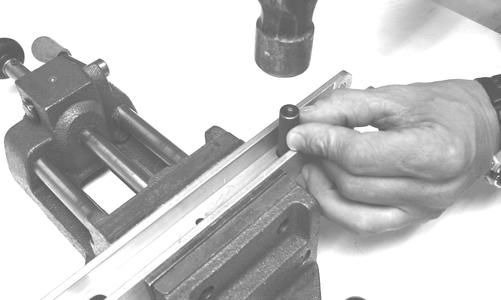
ZJ162
INSPECTING 1.Inspect the entire drag link (especially in the areas where the ball joints attach) for any signs of cracks, wear, or damage. 2.Inspect the bearings and axles for wear or damage.
INSTALLING 1.If the bearings were removed, place the drag link in a suitable vise and press the bearings into the drag link.
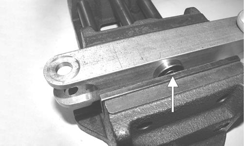
ZJ163A
2.Secure the steering arms to the drag link with the drag link axles, cap screws (E) (threads coated with blue Loctite #243), and new lock nuts (E). Tighten to 12 ft-lb.
0741-924
3.Place the steering arms/drag link assembly into position in the chassis; then secure the arms (D) with axles (F) to the chassis with cap screws and new lock nuts (C). Tighten the lock nuts to 20 ft-lb. 4.Install the left-side spindle tie rod and steering tie rod to the drag link with cap screw (threads coated with green Loctite #609) and new lock nut (B); then install the remaining tie rod to the drag link with cap screw (threads coated with green Loctite #609) and new lock nut (A). Tighten to 35 ft-lb. 5.Using an all-temperature grease, grease the steering arms; then verify free movement of the steering components.
2000 REMOVING AND DISASSEMBLING 1.Remove and discard the lock nut securing the inner tie rod to the spindle. NOTE: Note whether the inner tie rod is installed on
the top side or on the bottom side of the spindle arm for installing purposes.
2.Turn the handlebar in the appropriate direction and remove the cap screw and lock nut securing the inner tie rod to the drag link. Discard the lock nut. NOTE: To aid in removing the inner tie rod cap
screw from the drag link, position the drag link so the cap screw is aligned with the opening between the skid plate and the suspension mounting bracket.
ZJ159A
3.Loosen the jam nuts securing the ball joints to the tie rod; then remove the ball joints from the tie rod. CLEANING AND INSPECTING 1.Inspect the ball joints and tie rods for damaged threads or wear. 2.Inspect the ball joints and tie rods for cracks or unusual bends. 3.Wash the ball joint in parts-cleaning solvent. Dry with compressed air. Inspect the ball joint pivot area for wear. Apply an all-temperature grease to the ball joint.
ASSEMBLING AND INSTALLING 1.Install the jam nuts onto the ball joints; then thread the ball joints into the tie rod. 2.Secure the steering tie rod and the left-side inner tie rod to the drag link with the cap screw (threads coated with green Loctite #609) and new lock nut and tighten to 35 ft-lb; then secure the right-side inner tie rod to the spindle. Tighten the cap screws (threads coated with green Loctite #609) and new lock nuts to 30 ft-lb.
! WARNING
Always wear safety glasses when using compressed air.
3.Secure the right-side spindle tie rod to the drag link and spindle with the cap screws (threads coated with green Loctite #609) and new lock nuts; then tighten to 35 ft-lb. 4.Adjust ski alignment (see Ski Alignment in this section). 5.Tighten the jam nuts (coated with blue Loctite #243) against the tie rod to 13 ft-lb. ! WARNING
Neglecting to lock the jam nuts against the tie rod may cause loss of snowmobile control and possible personal injury.
3000/7000 NOTE: To access the steering arm, the steering tie
rods must be removed.
REMOVING 1.Remove both machine screws and nyloc nuts securing the steering tie rod ends to the steering arm. Discard both nuts.
SNO-350
5.Remove the lock nut securing the steering tie rod to the steering post. Discard the nut.
SNO-349
2.Remove the nyloc nuts securing the steering tie rod ends to the spindle arms. Account for the washers and discard both nuts.
SNO-353
3.Slide the steering tie rod out of the steering boot and out of the snowmobile. 4.Remove the screw and lock nut securing the steering tie rod end to the steering arm. Discard the nut.
SNO-351
NOTE: At this point if the technician’s objective is
to remove the steering arm, the reinforcement bracket will need to be removed by drilling out the appropriate rivets.
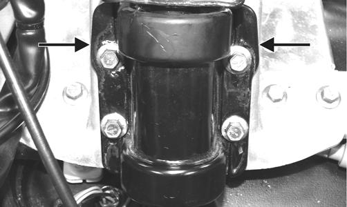
6.Remove all torx-head screws securing the front skid plate to the chassis; then remove the cap screw and nut securing the steering arm to the chassis. Account for two washers and two bushings.
SNO-225A
INSPECTING 1.Inspect the ball joints for damaged threads or wear. 2.Inspect the tie rod for damage, unusual bends, or wear. INSTALLING 1.Secure steering arm into position and secure using the existing cap screw, flat washers, and nut. Tighten to 96 in.-lb.
SNO-225A
2.Place the steering tie rod into position on the steering post. Secure with a new nyloc nut. Tighten to 35 ft-lb.

SNO-353
5.Secure the steering tie rod to the steering tie rod bracket with the screw and new nyloc nut. Tighten to 20 ft-lb.
SNO-351
NOTE: Make sure the tie rod tab is fully seated into
the steering post and threads of the ball joint are above the nut when tightened correctly.
3.Place the tie rod end into position on the steering tie rod bracket. Secure with a new nyloc nut. Tighten to 20 ft-lb.
SNO-350
4.Slide the steering tie rod through the steering boot and into the snowmobile; then place the steering tie rod into the spindle arm with the washer. Secure with a new nyloc nut. Tighten to 32 ft-lb.
SNO-349
Spindle
2000 REMOVING 1.Position the front of the snowmobile up on a safety stand. 2.Remove the ski. 3.Remove the tie rod cap and lock nut securing the tie-rod ball joint to the spindle; then remove the ball joint from the spindle. NOTE: Note whether the tie rod is installed on the
top side or on the bottom side of the spindle arm for installing purposes.
4.Remove the spindle cap and snap ring from the top of the spindle; then remove the cap screw securing the spindle arm to the spindle. Remove the spindle arm and account for and note the number of thrust washers for installing purposes.
ZJ172
ZJ177
NOTE: The cap screw must be removed to remove
the spindle from the spindle housing.
5.Using a soft hammer and a suitable driving tool, drive the spindle out of the spindle housing. 6.Remove the lock nut and cap screw securing the shock absorber to the spindle. Account for all mounting hardware.
ZJ173A
7.Remove the four torx-head cap screws securing the lower A-arm retainer to the spindle; then remove the cap and lower arm from the spindle.
ZJ174A
8.Remove the cap screw and lock nut securing the spindle to the upper A-arm. Account for all mounting hardware. INSPECTING 1.Inspect the spindle for excessive wear, cracks, bends, or imperfections. 2.Inspect all welds for cracking. 3.Inspect the A-arm bushings and axle area for wear. 4.Secure the spindle in a vise. Rotate the spindle clockwise and counterclockwise. The movement should be smooth and free. If the spindle movement is rough or binding, grease the spindle with an all-temperature grease. Rotate the spindle. If the movement remains rough, replace the spindle. NOTE: When greasing the spindle, use enough
grease so it can be seen coming out at both the top and bottom of the spindle.
5.Inspect the spindle axle and bearings for wear, damage, or loose fit. Replace the bearings as a set. 6.Inspect the tie-rod ball joint in place. If damage, wear, or unusual bends are noted, loosen the jam nut; then remove the ball joint from the tie rod. NOTE: Replacing the ski bolt bushings is difficult.
The existing bushings will be damaged during removal. Be careful, however, not to damage the spindle when removing the bushings. Press the new bushings into the spindle.
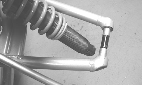
INSTALLING 1.Place the upper arm end (with axle) into position in the spindle. Secure with cap screw and lock nut.
Tighten only until snug. 2.Install new split bearings onto the shaft of the lower
A-arm; then using a suitable pliers, evenly compress the bearing until properly fitted to the shaft.
ZJ175A
NOTE: The split bearings cannot be reused; they
must be replaced with new ones.
3.Position the spindle into the lower A-arm; then install the retainer and secure the cap to the spindle with the four torx-head cap screws (coated with blue
Loctite #243). Tighten to 13 ft-lb.
ZJ174A
4.With the shock sleeve in place, align the lower shock eyelet with the mounting hole in the spindle; then secure with the cap screw, optional washers, and lock nut. Tighten to 32 ft-lb.
ZJ173A
5.At this point, tighten the lock nut (from step 1) to 32 ft-lb.
ZJ173B
6.Install the spindle into the spindle housing; then with the correct number of thrust washers (as noted in removing) and with the space (A) in the splines of the spindle aligned with the slot (B) in the steering arm, install the steering arm.
ZJ177
ZJ295A
7.Install the cap screw (threads coated with green Loctite #609) securing the steering arm to the spindle; then tighten to 40 ft-lb.
ZJ172
9.Place the steering tie-rod ball joint into position on the steering arm as noted during removing and secure with a lock nut. Tighten to 30 ft-lb; then install the tie rod cap. 10.Install the ski and tighten to 26 ft-lb. 11.Remove the safety stand from beneath the front end. 3000/7000 REMOVING
0747-904
1.Position the front of the snowmobile on a safety stand; then remove the ski. 2.Remove the cap screw and lock nut securing the shock absorber to the spindle. 3.Remove the lock nut securing the tie rod to the spindle arm. Account for the washer on the top side. 4.Remove the two lock nuts securing the spindle to the upper and lower A-arms; then using a rubber mallet, remove the arms from the spindle. 5.Remove the spindle. INSPECTING 1.Inspect the spindle for excessive wear, cracks, bends, or imperfections. 2.Inspect the A-arm bushings and axle area for wear. 3.Inspect the ski spindle axle and bearings for wear, damage, or loose fit. Replace the bearings as a set. NOTE: Replacing the ski bolt bushings is difficult.
The existing bushings will be damaged during removal. Be careful, however, not to damage the spindle when removing the bushings. Press the new bushings into the spindle.
0747-904
1.Place the shock absorber into position on the spindle.
Secure with the cap screw and lock nut. Tighten to 32 ft-lb. 2.Install the upper and lower A-arms into the spindle; then remove the snowmobile from the support stand.
Secure with new lock nuts. Tighten to 45 ft-lb. NOTE: The weight of the snowmobile will allow the
ball joints to seat into the spindle before tightening the nuts.
3.Place the tie rod with washer into position on the spindle arm. Secure with a new lock nut. Tighten to 32 ft-lb. 4.Install the ski. 5.Turn the handlebar fully to the right and then to the left to verify the steering moves freely.
Steering Tie Rod (2000)
REMOVING 1.Remove the springs securing the expansion chamber; then remove the expansion chamber from the engine compartment. Account for the two gaskets and the rubber exhaust bumper.
FS203A
2.Remove and discard the lock nut securing the steering tie rod to the steering post; then remove the cap screw and lock nut securing the left-side inner tie rod and steering tie rod to the drag link. Discard the lock nut.
FS260A
INSPECTING 1.Inspect the ball joints for damaged threads or wear. 2.Inspect the tie rod for damage, unusual bends, or wear. INSTALLING 1.Thread the jam nuts onto the ball joints; then equally thread the ball joints onto the steering tie rod. NOTE: There must be an approximate equal num-
ber of threads exposed on each ball joint.
2.Place the tie-rod assembly into position; then rotate the steering tie rod until the holes in the ball joints align with the holes in the steering post and the drag link. 3.Secure the steering tie rod to the steering post with the new lock nut and tighten to 35 ft-lb; then secure the steering tie rod and left-side inner tie rod to the drag link with the cap screw (threads coated with green Loctite #609) and new lock nut. Tighten to 35 ft-lb. 4.Ensure correct handlebar/ski alignment (adjust steering tie rod as necessary); then tighten the jam nut (coated with blue Loctite #243) to 13 ft-lb.
5.Place the rubber exhaust bumper into position on the air silencer. ! WARNING
Neglecting to lock the tie rod by tightening the jam nuts may cause loss of snowmobile control and possible personal injury.
FS203A
6.Place gaskets on the resonator and exhaust manifold; then install the expansion chamber. Secure the chamber to manifold and upper frame with the springs.
Ski Alignment
CHECKING NOTE: Track tension and alignment must be prop-
erly adjusted prior to checking or adjusting ski alignment. Ski alignment must be performed on a flat, level surface. Ski toe-out must fall within the range of 1/16-1/4 in.
1.Raise the front end of snowmobile just high enough to keep the skis from contacting the floor. 2.Turn the handlebar to the straight-ahead position.
Visually inspect the handlebar for being centered and in the straight-ahead position. 3.With the handlebar in the straight-ahead position, secure the handlebar to prevent the alignment from becoming disturbed during the remainder of the alignment procedure. NOTE: Track tension and alignment must be prop-
erly adjusted prior to placing the straightedge against the outside edge of the track.
4.Place a long straightedge against the outside edge of the track so it lies near the inside edge of the left-side ski.
729-887B
NOTE: The straightedge should be long enough to
extend from the back of the track to the front of the ski.
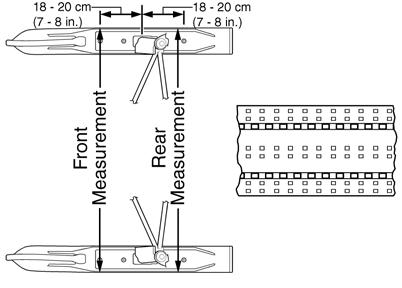
5.Measure the distance from the straightedge to the left-side ski wear bar bolts in two places: approximately 7-8 in. in front of the spindle and 7-8 in. behind the spindle. Record the measurements taken for the left side.
729-887A

0734-408
6.Place the straightedge against the outside edge of the track so it lies near the inside edge of the right-side ski. 7.Measure the distance from the straightedge to the right-side ski wear bar bolts in two places: 7-8 in. in front of the spindle and 7-8 in. behind the spindle.
Record the measurements taken for the right side.
8.If ski alignment is not as specified, adjust the alignment of the ski(s) not parallel to the straightedge. ADJUSTING NOTE: The following procedure can be used to
adjust the alignment of either ski.
To adjust ski alignment, use the following procedure. 1.Secure the steering tie rod in the centered position. 2.Loosen both inner tie rod jam nuts on the same side as the ski to be aligned. 3.Using a wrench on the spindle tie rod “flats,” rotate the spindle tie rod until recommended specification is attained. 4.Apply blue Loctite #243 to each jam nut thread area; then tighten the jam nuts against the inner tie rod.
Tighten to 13 ft-lb.
! WARNING
The measurement from the front and rear wear bar bolts to the straightedge can be equal (ski parallel to the track), but the front measurement must never be less (ski toed-in) or poor handling will be experienced. The front wear bar bolt measurement to the straightedge must not exceed the measurement from the rear wear bar bolt to the straightedge (ski toed-out) by more than 5/32 in.
NOTE: Repeat this procedure on each side (if neces-
sary) until ski toe-out is within specification.
! WARNING
Neglecting to lock the tie rod by tightening the jam nuts may cause loss of snowmobile control and possible personal injury.
VERIFYING 1.With the handlebar in the straight-ahead position, verify ski alignment by measuring across from the outside edge of the left-side wear bar bolts to the outside edge of the right-side wear bar bolts (without using the straightedge) in two places: approximately 7-8 in. in front of the spindle and 7-8 in. behind the spindle. 2.The measurement from in front of the spindle to the outer edge of the wear bar bolts (without using the straightedge) must not exceed the rear measurement by more than 1/16-1/4 in. toe-out.
0734-408
! WARNING
The measurement taken in front of the spindle must never be less than the measurement taken behind the spindle or poor handling will be experienced. Neglecting to lock the tie rod by tightening the jam nuts may cause loss of snowmobile control and possible personal injury.
A-Arms
2000 REMOVING UPPER ARMS NOTE: For installing purposes, note the position of
the axle shoulders.
ZJ168A
1.Elevate the front of the snowmobile with a suitable safety stand or lift.
2.Remove the cap screw and lock nut securing the upper arms to the spindle. Account for the spindle axle. 3.Remove the cap screw and lock nut securing the front upper arm to the chassis; then remove the cap screw and lock nut securing the rear upper arm to the chassis. Account for the axles. INSPECTING 1.Inspect the arm welded areas for cracks or any signs of deterioration. 2.Inspect the bearings and axles for wear or damage. 3.Inspect the arm tubing for signs of twisting or bending. INSTALLING UPPER ARMS 1.With the axles properly installed as noted during removing, install the front and rear upper arms to the chassis; then secure the arms with the cap screws and lock nuts. Tighten to 32 ft-lb. 2.With the axle installed in the spindle, secure the upper arms to the spindle with the cap screw and lock nut. Tighten to 32 ft-lb. REMOVING LOWER A-ARM 1.Elevate the front of the snowmobile with a suitable safety stand or lift. 2.Remove the cap screw and lock nut securing the shock absorber to the spindle; then remove the shock from the spindle and account for the shock sleeve. 3.Remove the four torx-head cap screws securing the lower A-arm retainer to the spindle; then remove the cap and lower arm from the spindle.
CAUTION
Never use the front bumper to support the front of the snowmobile off the floor.
ZJ174A
4.Secure the upper arms and spindle out of the way.
0744-929
5.Remove the cap screws and lock nuts securing the lower A-arm to the chassis; then remove the arm from the sway bar and chassis and account for the axles and sway bar link. NOTE: For installing purposes, note the position of
the axle shoulders.
ZJ168A
6.If applicable using a flat-blade screwdriver, pry the split bearings from the spindle axle of the A-arm. NOTE: The split bearings cannot be reused; they
must be replaced with new ones.
INSPECTING 1.Inspect the arm welded areas for cracks or any signs of deterioration. 2.Inspect the bearings and axles for wear or damage. 3.Inspect the arm tubing for signs of twisting or bending.
INSTALLING LOWER A-ARM 1.If removed, install new split bearings onto the shaft of the lower A-arm; then using a suitable pliers, evenly compress the bearing until properly fitted to the shaft. 2.Install the lower A-arm into the sway bar link and with the axles properly installed as noted in removing, place the arm into position in the chassis. NOTE: When installing the lower A-arm, position
the shock absorber to the inside of the spindle axle before securing the arm to the chassis.
ZJ175
3.Install the cap screws and lock nuts securing the
A-arm to the chassis; then tighten to 32 ft-lb. NOTE: When installing the rear cap screw of the
A-arm, keep the cap screw approximately 1/2 in. out from being fully installed allowing for easier installation of the lock nut.
4.Install the sway bar link to the lower A-arm. 5.Position the spindle into the lower A-arm; then install the lower A-arm retainer and secure the cap to the spindle with the four torx-head cap screws (coated with blue Loctite #243). Tighten to 13 ft-lb.
ZJ174A
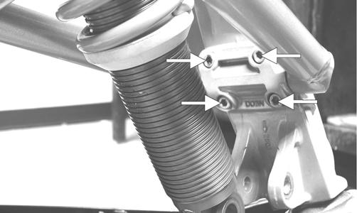
6.Install the shock absorber to the spindle; then install the cap screw and lock nut. Tighten to 32 ft-lb. 3000/7000 REMOVING 1.Elevate the front of the snowmobile and secure using a suitable support stand. 2.Remove the push rivets securing the steering boot to the chassis; then slide the boot away from the snowmobile. 3.Remove the torx-head screws securing the front skid plate to the chassis; then remove the front skid plate. 4.Remove the ski shock absorber. 5.Remove the two lock nuts securing the spindle to the
A-arms; then using a rubber mallet, remove the arms from the spindle. Discard the nuts.
SNO-354
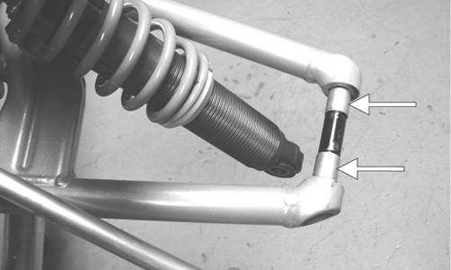
6.Remove the cap screw and lock nut securing the sway bar link to the lower arm. Discard the nut. 7.Remove the two cap screws and nyloc nuts securing the lower arm to the chassis; then slide the boot from the arm and remove the arm.
SNO-226A
8.Remove the two cap screws and lock nuts securing the upper arm to the chassis. Discard the nuts. INSPECTING 1.Inspect the arm welded areas for cracks or any signs of deterioration. 2.Inspect the bearings and axles for wear or damage. 3.Inspect the arm tubing for signs of twisting or bending. 4.Inspect mounting location of the chassis for cracks or wear. INSTALLING 1.Place the upper arm into position on the chassis and secure with the cap screws and new nyloc nuts.
Tighten to 23 ft-lb. 2.Slide the lower arm into the boot; then place the arm into position on the chassis. Secure with the cap screws and new nyloc nuts and tighten to 55 ft-lb (front) and 45 ft-lb (rear).
SNO-226A
3. Secure the sway bar link to the lower arm with the cap screw and new nyloc nut. Tighten to 23 ft-lb. 4. Secure the A-arms to the spindle. 5. Install the ski shock absorber. 6. Place the front skid plate into position; then secure with the torx-head screws.
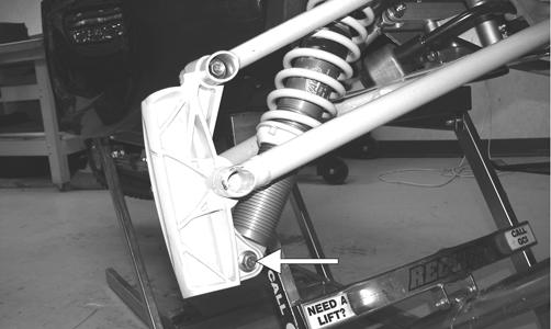
Ski Shock Absorber
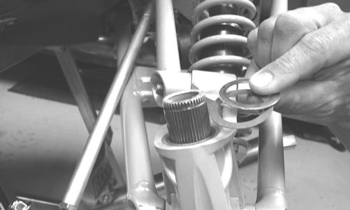
REMOVING 1.Position the front of the snowmobile on a safety stand taking all pressure off the skis. 2.Remove the cap screws securing the shock absorber to the chassis and spindle; then remove the shock absorber. Account for all mounting hardware. NOTE: Note the number of threads exposed
between the spring adjuster and shock housing for installing purposes.
3.Using the Shock Spring Removal Tool, remove the spring from the shock body by compressing the spring; then remove the spring retainer from the top of the spring. Inspect the shock absorber by quickly compressing and extending the shock plunger while firmly holding the shock body. Resistance must be felt in both directions. CLEANING AND INSPECTING 1.Inspect the shock absorber seal area for signs of excessive oil leakage. 2.Inspect the shock absorber mounting eyelet, bushings, and sleeve for wear or damage. 3.Inspect the threaded shock sleeve for damage or wear. Clean the sleeve and apply a light coat of grease to the threads before installing. INSTALLING 1.Using the shock spring tool, place the spring on the shock absorber and secure with the retainer. 2.Adjust the retainer nut (spring adjuster) (if applicable) until the specified amount of threads are exposed between the spring adjuster and the shock housing (noted in removing) as an initial setting. 3.Install the bushings, sleeves, and spacers into each shock end; then place the shock absorber into position and secure with the cap screws and lock nuts.
Tighten the lock nuts to 32 ft-lb.
Sway Bar (Lynx Models)
REMOVING 1.Remove the two lock nuts securing the sway bar mounting brackets to the chassis; then using a soft hammer, tap the sway bar in either direction until the sway bar link is off the pin on the A-arm.
0744-929
2.Slide the sway bar out of the chassis and account for the sway bar links and four sleeves. INSPECTING 1.Inspect the sway bar for any signs of twisting, fatigue, or wear. 2.Inspect the sway bar links for cracks or damage. INSTALLING 1.Place the sway bar into position in the chassis; then install the sway bar links to each end of the sway bar and position the links onto the pins of the A-arms. 2.With the sway bar properly positioned in the chassis, install the sleeves onto the sway bar. Install the sway bar mounting brackets and secure the brackets with the lock nuts. Tighten to 120 in.-lb.
Front Suspension Mounting Bracket (2000)
REMOVING 1.Elevate the front of the snowmobile with a suitable safety stand or lift. NOTE: For the following steps, refer to the illustra-
tion.
2.Remove the lock nut (A) securing the steering post to the suspension mounting bracket. 3.Remove the cap screw and lock nut (B) securing the steering tie rod and inner tie rod to the drag link. 4.Remove the lock nuts (C) securing the two sway bar mounting brackets to the suspension mounting bracket; then remove the brackets accounting for the sleeves.
0744-930
5.Remove the sway bar/links (D) from the pins of the left-side/right-side lower A-arms. 6.Remove all cap screws and lock nuts corresponding to (E) securing the left-side lower A-arm and the left-side upper A-arms to the suspension mounting bracket. NOTE: At this point, remove all cap screws and lock
nuts corresponding to (E) securing the right-side upper A-arms and lower A-arm to the suspension mounting bracket.
7.Move the arms away from the bracket and account for the axles (F). 8.Remove the lock nut from the cap screw (G) securing the left-side shock absorber to the shock mounting frame; then remove the cap screw and remove the left-side steering/suspension components. 9.Remove the cap screws and lock nuts (H) securing the two steering arms to the suspension mounting bracket. 10.Remove the lock nuts and cap screws (I) securing the two shock absorber mounting frames to the suspension mounting bracket; then remove the four lock nuts and cap screws (J) securing the shock mounting frames to the front upper frame. NOTE: Remove the cap screws and lock nuts (K)
and (L) from the suspension mounting bracket.
NOTE: Remove the lock nut from the cap screw
corresponding to (G) - left-side securing the right-side shock absorber to the shock mounting frame; then remove the cap screw and slide the right-side steering/suspension assembly out of the suspension mounting bracket. Account for the axles and the shock absorber sleeve.
INSTALLING NOTE: For the following procedure, refer to illus-
tration on the previous page.
1.Install the steering post with the proper number of washers as noted during removing to the suspension mounting bracket with the lock nut (threads coated with green Loctite #609) (A). Tighten only until snug.
ZJ169
2.Place the suspension mounting bracket into position in the chassis; then secure the bracket to the chassis with the four upper (K) and four lower (L) cap screws and lock nuts. Tighten until snug. NOTE: For ease of installing, do not tighten the four
upper and lower cap screws and lock nuts (K) and (L) until step 14.
3.Tighten the lock nut (A) securing the steering post to the chassis (from step 1) to 35 ft-lb. 4.Secure the two shock absorber mounting frames to the suspension mounting bracket with cap screws and lock nuts (I); then tighten to 96 in.-lb. Tighten the four front frame cap screws and lock nuts (J) to 20 ft-lb. NOTE: When installing the following steering/sus-
pension components, tighten the cap screws and lock nuts only until snug until step 13.
5.At this time to install the right-side steering/suspension components, first install the shock with sleeve to the shock mounting frame with cap screw and lock nut corresponding to (G) - left-side. 6.At this time, position the drag link and steering arms into the suspension mounting bracket; then with axles in place, install the right-side upper A-arms and lower A-arm with all cap screws and lock nuts corresponding to (E). NOTE: When installing the A-arms, make sure the
axle shoulders are properly positioned.
ZJ168A
7.Install the right-side steering arm with cap screw and lock nut (H). 8.To install the left-side steering components, first place the sway bar into the sway bar link on the right-side A-arm; then move the sway bar to the mounting position. 9.Install the left-side shock absorber with sleeve to the shock mounting frame with cap screw and lock nut (G). 10.With the axles (F) properly installed, install the left-side upper A-arms; then install the lower A-arm with all cap screws and lock nuts corresponding to (E). 11.Install the left-side steering arm with axle to the suspension mounting bracket with cap screw and lock nut corresponding to (H) - right-side. 12.Install the left-side inner tie rod and the steering tie rod to the drag link with cap screw and lock nut (B). 13.Tighten all steering/suspension components (from steps 5-7 and 9-12) in the following sequence and to the indicated torque values:
Step 5 Lock Nut (G) - RH 32 ft-lb Step 6 Lock Nut (E) - RH 32 ft-lb Step 7 Lock Nut (H) - RH 20 ft-lb Step 9 Lock Nut (G) - LH 32 ft-lb Step 10 Lock Nuts (E) - LH 32 ft-lb Step 11 Lock Nut (H) - LH 20 ft-lb Step 12 Lock Nut (B) 35 ft-lb
14.Tighten the cap screws and lock nuts (K) and (L) securing the suspension mounting bracket to the chassis (from step 2) to 30 ft-lb (upper) and 12 ft-lb (lower). 15.With the sleeves in place on the sway bar, position the sway bar links (D) onto the sway bar; then install the sway bar/links onto the left-side/right-side lower
A-arm pins. 16.Secure the sway bar to the suspension mounting bracket with the sway bar mounting brackets and lock nuts (C). Tighten securely.
Seat Assembly
2000 REMOVING 1.Remove the hood and open the right-side and left-side access panels. 2.Remove the two torx-head screws securing the console to the chassis; then lift up the rearward end of the console and disconnect the console harness plug-in. Remove the console.
0743-777
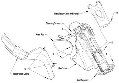
3.Remove the two torx-head cap screws (B) securing the handlebar close-off panel; then remove the three torx-head cap screws (C) securing the rear side panels (spars) to the seat support tubes.
741-965A
4.Remove the two screws (D) securing the knee pads to the gas tank; then remove the remaining body screws securing the knee pads to the steering support.
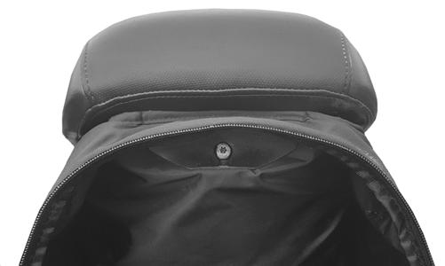
5.Push down on both seat retainer brackets (located in the rear storage compartment) and remove the seat. INSTALLING 1.Install the screws (D) and the body screws securing the knee pads to the gas tank and the steering support; then secure the rear side panels (spars) with the three torx-head cap screws (C) for each side. 2.Install the handlebar close-off panel; then secure the panel with the two torx-head cap screws (B). Position the console assembly on the headlight support bracket; then connect the main hood harness. 3.Install the console to the steering support with the two torx-head cap screws. Tighten securely. 4.Install the hood; then close the side access panels. 5.Place the seat into position on the chassis; then push down on the rear of the seat until it locks securely in place. 3000 REMOVING/INSTALLING 1.Unzip the rear storage bag; then remove the screw securing the bag and the seat. Remove the seat.
BC320
2.To install the seat, route the front tab on the operator seat through the seat-base hold-down bracket; then secure the rear of the seat and the rear storage bag using the existing screw. Tighten securely. Close the rear storage bag. 7000 REMOVING 1.Open the hood and remove both access panels. 2.Lift up the lever on the rear of the seat and hold it in that position; then lift and remove the passenger seat.
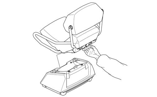
0749-032
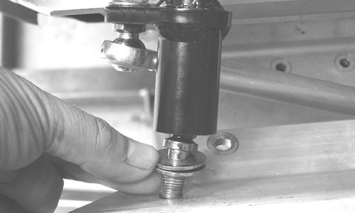
3.Open the storage box door; then remove the two shoulder torx screws securing the storage box and remove the storage box. 4.Remove the four self-tapping screws securing the front seat fascia to the right- and left-side seat fascia. 6.Remove the gas line vent hose from the check valve; then disconnect the gasline hose connector hose from the outlet of the fuel pump by pressing inward on the white connector, pressing in the black release, and finally pulling back on the hose.
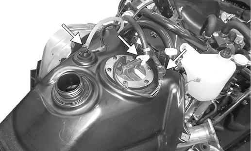
BC257A
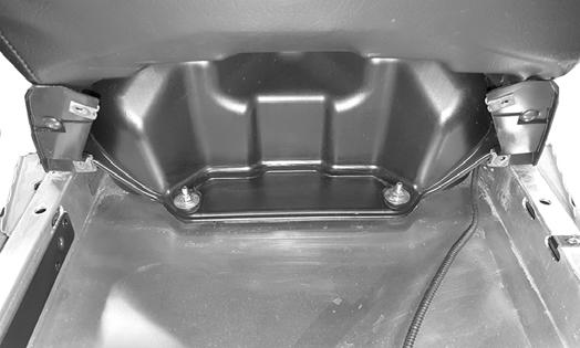
7.Remove the two lock nuts and washers securing the rear of the gas tank assembly to the tunnel. Remove the gas tank making sure to install the gas cap to avoid any fuel from spilling.
BC266A
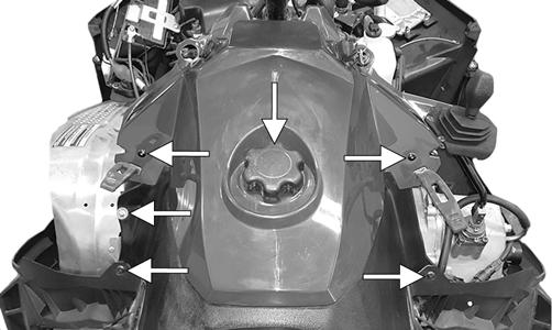
5.Remove the self-tapping screws, gas tank cap, and gasket securing the console assembly; then disconnect the ignition switch, reverse alarm, and the accessory outlet. Remove the console.
BC258A
WARNING
Since the fuel supply hose may be under pressure, remove it slowly to release the pressure. Place an absorbent towel around the connection to absorb gasoline; then remove the hose slowly to release the pressure. Always wear safety glasses when removing the fuel hose.
BC259
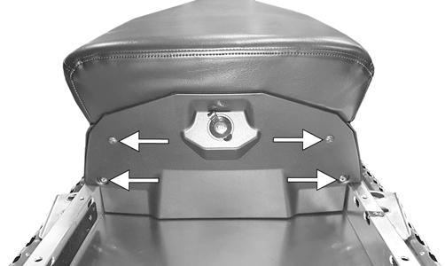
8.Remove the screws securing the gas tank to the seat base.
BC265A
INSTALLING 1.Install the gas tank assembly and secure using the existing flat washer, nuts, and self-tapping screws. connect the seat heater connection; then install the rear fascia and secure using the existing self-tapping screws.
2.Position the console assembly over the gas tank and connect the, seat heater switch, ignition switch, reverse alarm, and the accessory outlet. Install the gas tank cap. 3.Install both access panels and close and latch the hood.
Seat Cushion
REMOVING 1. Remove the seat assembly (see the appropriate Seat
Assembly in this section). 2.Remove the two screws securing the taillight cover and remove the cover; then remove the two screws securing the front of the seat cushion to the seat base. 3. Using a sharp tool, pry out all staples securing the seat cover to the plastic seat base. 4. From beneath the seat foam, remove the seat wire from the two elastic loops; then remove the cover from the seat base and seat foam. INSTALLING 1.Position the cover over the seat foam and seat base; then pull the two elastic loops through the slots in the seat foam and secure with the seat wire. Check to make sure it is positioned straight. 2. Fold the rear edge of the cushion down and around the plastic base. Using a staple gun and 1/4 in. staples, staple the rear flap of the cushion to the plastic base in the same areas as the original staples were located. Position staples 1 in. apart. 3. Fold the sides of the cushion down around the bottom edge of the plastic seat base. Position the staples in the same area as the original staples were located. NOTE: Note the cushion fit. If any wrinkles are
noted, remove by pulling the cushion material in the appropriate direction before securing with staples.
4.Fold the front cushion material back and onto the plastic seat base. Check for wrinkles and secure with staples. 5. Install the seat assembly.
Taillight/Brakelight Assembly
BEARCAT 7000
0749-425
1.Remove the two screws on either side of the taillight then carefully pull back the taillight panel to access the taillight connector. 2.Disconnect the taillight harness connector. 3.Remove the two nuts securing the taillight. 4.Connect the taillight harness connector; then secure the taillight to the bracket with the two nuts. 5.Position the taillight panel and secure using the two screws. BEARCAT 3000 LT
0749-426
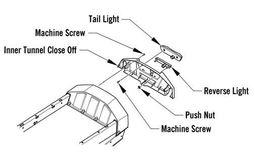
1.Remove the self-tapping screws securing the taillight cover. 2.Remove the machine screws securing the taillight; then disconnect the harness. 3.Connect the taillight harness connector; then secure the taillight to the bracket with the torx-head screws. BEARCAT 2000 XT 1.Remove the four pins securing the rear seat to the seat/Speedrack mount; then remove the seat.
0743-329
2.Compress the latch on the right side of the front seat and lift the front seat away; then disconnect the taillight harness connector.
0743-444
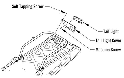
3.Loosen (but do not remove) the three right-side seat/Speedrack mount cap screws. 4.Carefully route the harness connector through the hole in the storage compartment panel; then remove the harness from beneath the seat/Speedrack mount. 5.Remove the two self-tapping screws securing the taillight to the bumper; then route the harness out of the bumper and remove the taillight. 6.Route the taillight harness through the bumper; then secure the taillight to the bumper with the two self-tapping screws. 7.Carefully route the harness beneath the Speedrack mount and through the hole in the storage compartment panel; then connect the harness connector. 8.Tighten the three right-side mount cap screws; then lower the front seat. 9.Place the rear seat into position on the mount making sure the four pin holes are properly aligned with the mounting location on the mount. 10.Install the four pins making sure they are properly seated.
! WARNING
Make sure the rear seat is securely locked in place with the four pins before carrying a passenger or personal injury may result.
BEARCAT 2000/Lynx 2000 LT 1.Remove the torx-head cap screws securing the taillight access panel.
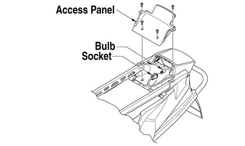
742-467A
2.Disconnect the harness connector and remove housing. 3.Push in on the socket and rotate it counterclockwise to remove it from the housing. 4.Remove the old bulb by pulling it straight out of the socket. 5.Install the new bulb in the socket by pushing it straight in. 6.Push the socket into the housing and rotate it clockwise to lock into place. 7.Connect the harness connector. 8.Secure the access panel with the torx-head cap screws.
Rear Bumper/Snowflap
BEARCAT 7000 REMOVING 1.Remove the machine screws securing the rear bumper to the tunnel. 2.Slide the bumper off the tunnel. 3.Remove the rivets securing the snowflap to the tunnel. INSTALLING 1.Secure the snowflap to the tunnel using new rivets. 2.Position the bumper onto the tunnel aligning with the holes in the tunnel. Secure using the existing machine screws. Tighten securely. BEARCAT 2000 XT REMOVING NOTE: The snowflap can be removed without
removing the bumper by removing the four torx-head cap screws and lock nuts.
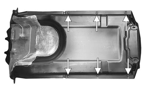
1.Remove the four torx-head cap screws and lock nuts securing the bumper assembly to the running board; then remove the four lock nuts from under the tunnel. Account for the U-nuts and cap screws.
2.Slide the bumper off the tunnel. 3.Remove the four torx-head cap screws securing the snowflap to the tunnel. Account for cap screws, washers, and lock nuts. INSTALLING 1.Secure the snowflap to the tunnel with the cap screws, washers, and lock nuts taking care to place the washers next to the underside of the snowflap.
Finger-tighten the cap screws to the lock nuts; then tighten the cap screws to 20 ft-lb. 2.Place the bumper assembly into position on the tunnel and secure to the running boards with the torx-head cap screws; then from under the tunnel, install the four lock nuts and tighten to 20 ft-lb. BEARCAT 2000/LYNX 2000 LT REMOVING 1.Remove the four torx-head cap screws, lock nuts, and washers securing the snowflap to the tunnel. 2.Remove the right- and left-side rear fenders; then carefully drill out the rivets from the back side of the tunnel.
CAUTION
Use caution when drilling the rivets from the rear bumper and snowflap not to damage the heat exchangers.
INSTALLING 1.Install the rear bumper and with the holes properly aligned, secure the bumper to the tunnel with rivets; then install and secure the rear fenders. 2.With the snowflap support in place, install the snowflap and secure with the torx-head cap screws, washers, and lock nuts. LYNX 2000 REMOVING NOTE: The snowflap can be removed without
removing the bumper by removing the five rivets securing the snowflap to the heat exchanger and compressing the two flanged tabs located on the underside of the tunnel.
1.Remove the four machine screws securing the bumper to the tunnel; then carefully drill out the rivets securing the bumper to the tunnel.
Use caution when drilling the rivets from the rear bumper and snowflap not to damage the heat exchangers.
2.Remove the bumper. INSTALLING Place the bumper into position on the tunnel; then install the four machine screws and rivets securing the bumper to the tunnel. Tighten the screws to 96 in.-lb.
Headlight Assembly
3000/7000 NOTE: The bulb portion of headlight is fragile.
HANDLE WITH CARE. When replacing the headlight bulb, the bulb assembly must first be removed from the housing. Do not touch the glass portion of the bulb. If the glass is touched, it must be cleaned with a dry cloth before installing.
1.Disconnect the headlight harness connector from the bulb; then remove the rubber grommet from the headlight housing. 2.Rotate the bulb retainer counterclockwise until it unlocks from the housing; then remove the bulb.
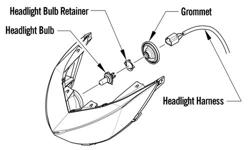
0746-096
3.Install the bulb and retainer; then rotate the retainer clockwise until it properly locks in place. 4.Install the rubber grommet; then connect the headlight harness connector to the bulb. 5.Check headlight aim. ! WARNING
Do not operate the snowmobile unless headlight beam is adjusted properly. An incorrectly adjusted beam will not provide the operator the optimum amount of light.
2000 REMOVING HEADLIGHT BULB NOTE: The bulb portion of the headlight is fragile.
HANDLE WITH CARE. When replacing the headlight bulb, the bulb assembly must first be removed from the housing. Do not touch the glass portion of the bulb. If the glass is touched, it must be cleaned with a dry cloth before installing.
1.Remove the two torx-head screws located to the outside of the headlight adjustment knobs; then remove the single torx-head cap screw from beneath the console (located between the headlights).
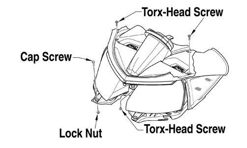
743-439A
2.Remove the cap screw and lock nut securing the front of the headlight assembly to the air silencer. 3.Lift the front of the console enough to allow the headlight housing to be removed; then remove the housing. 4.Remove the bulb from the headlight housing and disconnect the wiring harness from the bulb.
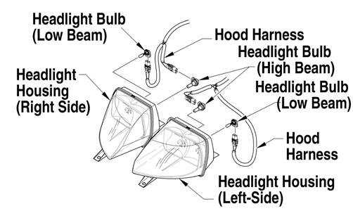
741-329A
INSTALLING HEADLIGHT BULB CAUTION
Do not touch the glass portion of the bulb. If the glass portion is touched, it must be cleaned with a dry cloth before installing.
1.Plug the wiring harness into the headlight bulb. 2.Insert the bulb into the headlight housing. 3.Lift the front of the console enough to allow the headlight housing to be installed; then install the housing making sure the forks of the housing go into the grommets on top of the air silencer. Secure with the cap screw and lock nut.
743-439A
4.Position the console onto the air silencer; then secure with the single torx-head cap screw beneath the console (located between the headlights). 5.Install the two torx-head screws located to the outside of the headlight adjustment knobs; then tighten securely. 6.Check headlight aim (see Adjusting Headlight Aim in this section).
! WARNING
Do not operate the snowmobile unless headlight beam is adjusted properly. An incorrectly adjusted beam will not provide the operator the optimum amount of light.
Windshield
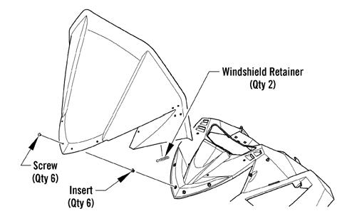
7000 REMOVING 1.Open the hood, then remove the two windshield retainers securing the windshield to the hood. 2.Remove the six screws securing the windshield.
Remove the windshield. INSTALLING
0748-982
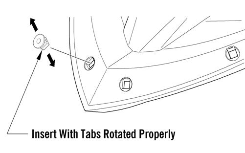
1.Install the six inserts into the hood; then position the windshield onto the hood and secure using the six screws. Do not over-tighten. NOTE: Make sure when installing the inserts into
the hood that the tabs open up to the sides.
0749-296
2.Open the hood; then install both windshield retainers securing the windshield through the hood. 2000 NOTE: If removing the console only, the windshield
does not have to be removed.
REMOVING 1.Remove the plastic rivet securing the front of the windshield to the windshield bracket. 2.Remove the two torx-head screws securing the windshield to the console; then separate the windshield from the console. INSTALLING
741-637A
1.Place the windshield into position on the console. 2.Secure the windshield to the console with the two torx-head screws. 3.Using a new plastic rivet, secure the windshield to the windshield bracket.
Console (2000)
REMOVING 1.Remove the two torx-head screws securing the console to the chassis; then lift up the rearward end of the console and disconnect the console harness plug-in.
0743-777
2.Remove the console. INSTALLING 1.Place the console into position on the headlight support bracket; then connect the console harness plug-in. 2.Secure the console to the chassis with the two torx-head screws.
Adjusting Headlight Aim
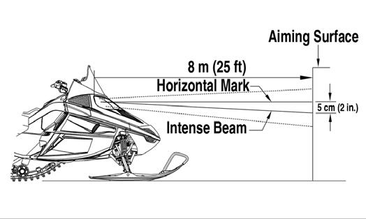
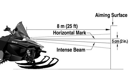
1.Position the snowmobile on a level floor so the headlight is approximately 8 m (25 ft) from an aiming surface (wall or similar surface). NOTE: There should be a 82 kg (180 lb) operating
load on the snowmobile when adjusting headlight aim.
2.Measure the distance from the floor to midpoint of the headlight. 3.Using the measurement obtained in step 2, make a horizontal mark on the aiming surface. 4.Make a vertical mark which intersects the horizontal mark on the aiming surface directly in front of the headlight. 5.Engage the brake lever lock and start the engine.
Move the headlight dimmer switch to the HIGH beam position. DO NOT USE LOW BEAM. 6.Observe the headlight beam aim. Proper aim is when the high beam is centered on the vertical mark 5 cm (2 in.) below the horizontal mark on the aiming surface.
0741-448
SNO-520A
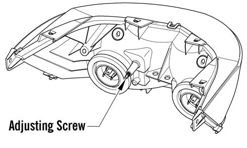
7.On 2000 models, adjust the headlight adjustment knobs until correct aim is obtained. Shut the engine off; then disengage the brake lever lock. 8.On 3000/7000 models, adjust the headlight using the adjusting screw on the backside of the headlight.
Shut the engine off; then disengage the brake lever lock.
0746-807
Printed in U.S.A. Trademarks of Arctic Cat Inc., Thief River Falls, MN 56701 p/n 2261-695