19 minute read
Engine-Related Items

NOTE: Whenever a part is worn excessively,
cracked, or damaged in any way, replacement is necessary.
SPECIAL TOOLS A number of special tools must be available to the technician when servicing the engine-related items. NOTE: When indicated for use, each special tool
will be identified by its specific name, as shown in the chart below, and capitalized.
Description p/n
Blind-Hole Bearing Puller 0644-500 Coolant Cap 0644-156 Drive Clutch Spanner Wrench 0644-136 Valve and Spring Retainer Tool 0644-448 Fan Spanner Wrench 0644-340 Water Pump Bearing and Seal Tool Kit 0644-557 Oil Seal Protector Tool 0644-219 Engine Leak-Down Test Kit 0644-522 Vacuum Test Pump 0644-131 Hood Harness Extension 1686-659 Hood Harness Extension 1686-660 Oil Filter Wrench 0644-551
NOTE: Special tools are available from the Arctic
Cat Service Parts Department.
Water Pump (3000)
REMOVING NOTE: The water pump is a non-serviceable com-
ponent. It must be replaced as an assembly.
1.Remove both access panels; then remove the hood.
Remove the resonator and drain the engine oil. 2.Using appropriate clamps, close off the coolant hose before and after the water pump. 3.Drain the coolant from the pump and remove the hoses from the water pump. 4.Remove the cap screws securing the magneto cover to the engine. 5.Remove the cap screws securing the impeller cover to the magneto cover. Account for an O-ring and two dowel pins.
WT578
6.Remove the E-clip and washer from the impeller shaft and remove the impeller from the case half.
WT571
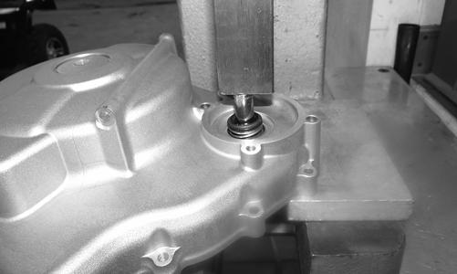
7.Using an appropriate press, remove the two bearings.
WT572
8.Using an appropriate press, remove the rubber seal and mechanical seal as an assembly.
WT570
INSTALLING 1.Apply grease to the inside and outside of the new seal; then press in the seal.
WT576A
CAUTION
Only apply pressure to the center race of the seal while installing to avoid damaging the seal.
2.Using a section of 1” pipe, press in the mechanical seal.
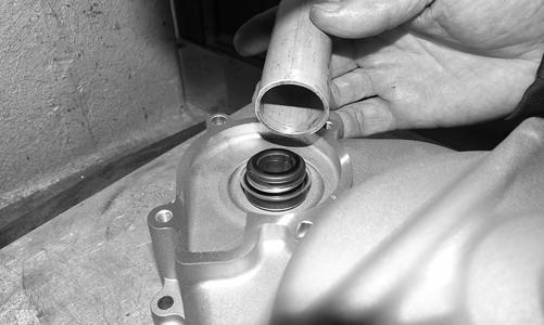
WT575
CAUTION
It is critical while pressing the seal into position to press on the outer diameter of the seal to avoid damaging the mechanical seal.
3.Individually press in the bearings.

WT573
4.Install the impeller in place and secure with a washer and E-clip. 5.Install the magneto cover and secure with the cap screws. Tighten the screws to 11 ft-lb using a criss-cross pattern. 6.Install the impeller cover and secure with the cap screws. Tighten the screws to 11 ft-lb. NOTE: The two longer cap screws go in the dowel
pin locations.
7.Install the coolant hoses; then add the appropriate mixture of coolant until the appropriate level is reached. 8.Install the resonator, hood and both access panels. 9.Add the appropriate engine oil until the correct level has been reached.
Water Pump (7000)
REMOVING 1.Open the hood and remove the left-side access panel; then remove the battery and drain the engine coolant. 2.Remove the drive clutch, drive belt, driven clutch; then remove the four screws securing the vent duct and screen to the skid plate. Remove the duct.
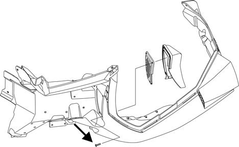
SNO-662A
3.Remove the screws securing the heat shield; then remove the shield.
BC300A
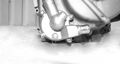
4. Disconnect all hoses from the water pump; then remove the Allen-head screws securing the water pump assembly to the crankcase. Remove the assembly. Account for two dowel pins and two gaskets.
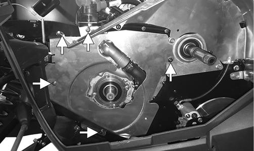
SNO-278
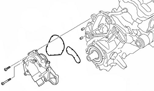
DISASSEMBLING/ASSEMBLING
SNO-372
1.Obtain top-dead-center (TDC) by rotating the crankshaft (clockwise) until the mark on the magneto rotor is aligned with the pointer on the magneto cover and the #3 piston is at TDC.
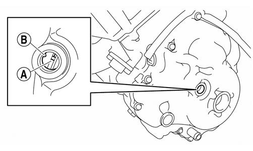
SNO-279A
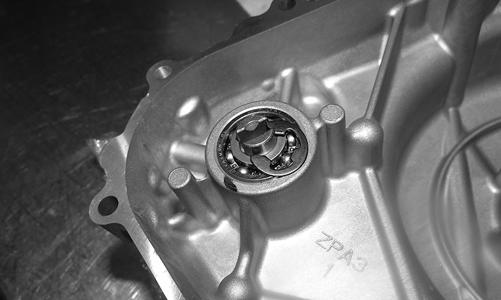
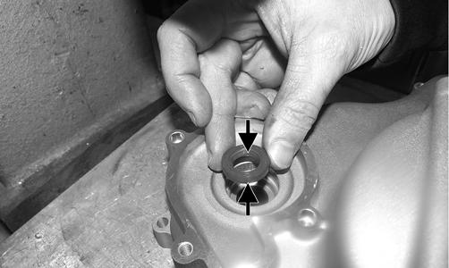
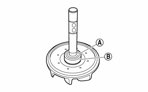
2.Remove the screws securing the water pump cover to the water pump; then remove the impeller. 3.Remove the water pump seal (A) from the water pump housing (B).

SNO-373A
4.Remove the bearing (A) and the oil seal (B) from the water pump housing (C).
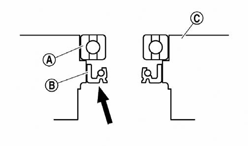
SNO-374A
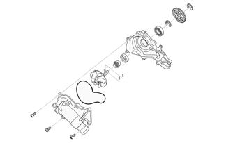
5.Remove the rubber damper holder (A) and the rubber damper (B) from the impeller using a small flat-head screwdriver making sure not to damage the impeller shaft.

SNO-375A
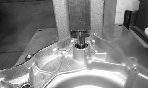
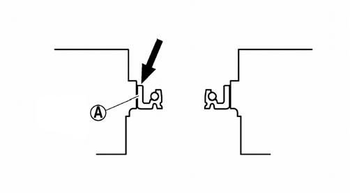
INSTALLING 1.Apply tap water or coolant to the outer surface of the new oil seal; then install the oil seal (A) into the water pump housing using a socket of the same diameter.
SNO-376A
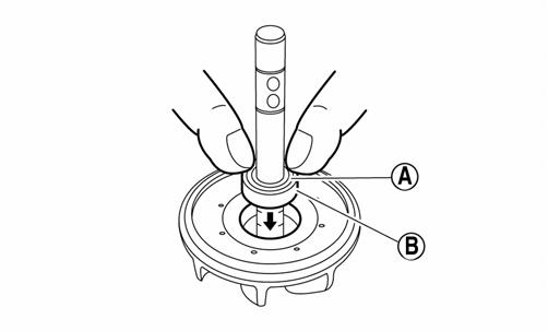
2.Install the bearing using a socket of the same diameter; then apply sealant to the water pump housing; then install the water pump seal using the mechanical seal installation tool.
3.Apply tab water or coolant to the impeller shaft; then press the rubber damper holder (A) and rubber damper (B) onto the impeller shaft.
CAUTION
Never apply oil or grease onto the water pump seal surface.
SNO-378A
4.Using a straight edge, make sure the impeller is flush with the damper.
SNO-379
5.Install the impeller assembly into the housing and secure using the existing circlip. 6.With the engine still at Top-Dead-Center (TDC), install the water pump and secure using the existing screws. Tighten to 8.7 ft-lb. 7.Fill the cooling system; then install the heat shield and left-side air duct using the existing screws. 8.Install the drive clutch, drive belt, and the driven clutch. 9.Install and connect the battery. Install the left-side access panel and close and latch the hood.
Pressure Testing Engine
NOTE: To pressure test the engine, use Engine
Leak-Down Test Kit.
Checking Compression
NOTE: Prior to this test procedure, verify the bat-
tery is fully charged and the console is positioned over the support bracket with the hood/main harness plugged in.
NOTE: This test must be done with the engine at
operating temperature and “full-cranking RPM” and the decompression system active.
3000 NOTE: The engine should be warm (operating tem-
perature) and the battery fully charged for an accurate compression test.
1.Remove the spark plug wires from the spark plugs. 2.Using compressed air, blow any debris from around the spark plugs. ! WARNING
Always wear safety glasses when using compressed air.
3.Remove the spark plugs; then attach the spark plug wires to the plugs and ground the plugs on the cylinder heads well away from the spark plug holes. 4.Attach the Compression Tester Kit.
5.While holding the throttle in the full-open position, crank the engine over with the electric starter until the gauge stops climbing (five to 10 compression strokes). Compression should be as shown in the chart.
6.If compression is abnormally low, verify the following: A.Starter cranks engine over (normal speed). B.Gauge is functioning properly. C.Throttle in the full-open position. D.Valve/tappet clearance correct. E.Engine warmed up. 7.If compression is still low, check for blown cylinder head gasket, valve leakage, or worn piston rings or cylinder (see Engine – Servicing Top-Side Components). 7000 With the spark plugs removed, install the compression tester gauge with adapter into the spark plug hole; then with the throttle valve in the full-open position, crank the engine over to get the psi reading. Compression should be 213.3 psi
PSI (WOT)
Cylinder #1/Cylinder #2 185
CAUTION
Do not ground the spark plug on the cylinder head cover. The cover is made of magnesium and any contact with spark or electrical arc will severely pit the surface.
NOTE: Verify both cylinder compression readings
are within 10% of each other.
Changing Oil/Filter
3000 NOTE: Recycle or properly dispose of the used
engine oil.
NOTE: The access panels and hood must be
removed for this procedure.
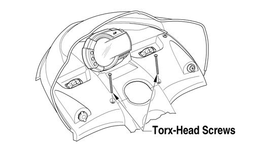
1.Park the snowmobile on a level surface; then start the engine and let it idle and warm up until the fan on the radiator turns on, or if the snowmobile was operated, allow the engine to idle for approximately 30 seconds. Shut the engine off. 2.Remove the torx-head screws and the rear access plate from beneath the snowmobile. 3.Place a drain pan beneath the engine oil drain screw; then remove the screw and allow the oil to drain completely.
XM318A
4.Using Oil Filter Wrench, loosen (but do not remove) the oil filter and allow the oil to drain from the filter into the drain pan; then remove the filter.
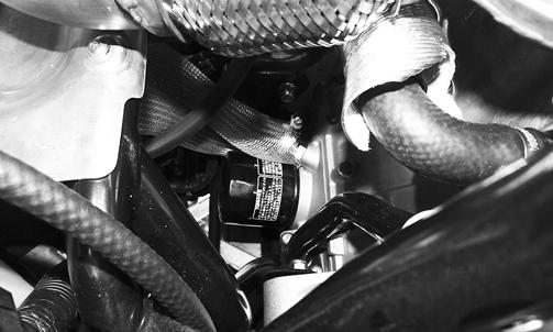
XM323
5.Apply a light coat of fresh engine oil to the seal of the new oil filter. 6.Install the new oil filter by turning the oil filter by hand until the seal has contacted the oil filter mounting surface; then tighten the oil filter to 12 ft-lb. 7.Install the engine oil drain screw with a new gasket.
Tighten the screw to 10 ft-lb. 8.Pour 2.8 L (3 US quarts) of engine oil in through the oil level stick tube. 9.Install the oil level stick then start the engine and check for the oil pressure warning icon. NOTE: The warning icon should go out within five
seconds. If it does, proceed to step 10. If the warning icon does not illuminate, take the snowmobile to an authorized Arctic Cat Snowmobile dealer for service. If not under warranty, this service is at the discretion and expense of the snowmobile owner.
10.Shut the engine off; remove the oil level stick from the oil tank and verify it is within the operating range on the stick.
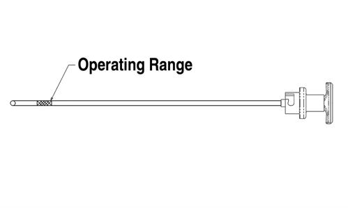
SNO-525A
NOTE: If the oil and engine are not at operating
temperature, the oil level may read too low. Always make sure the engine is at operating temperature before checking the oil.
12.Install the access plate beneath the engine; then install the hood and both access panels. 7000
! WARNING
Engine oil is extremely hot immediately after the engine is turned off. Burning could occur if oil contacts skin or clothing.
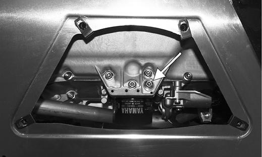
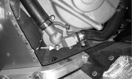
1.Park the snowmobile on a level surface; start the engine and let it idle and warm up until the fan on the radiator turns on, or if the snowmobile was operated, allow the engine to idle for approximately 30 seconds. Shut the engine off and allow the engine to cool. 2.Remove the torx-head screws securing the skid plate and access plate from beneath the engine. 3.Place a drain pan beneath the engine oil pan drain plug; then remove the plug and allow the oil to drain completely.
XM306A
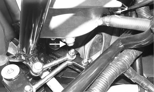
4.Using Oil Filter Wrench, loosen (but do not remove) the oil filter and allow the oil to drain from the filter into the drain pan; then remove the filter. 5.Open the hood; then remove the air temperature sensor and the three hoses from the air silencer. Loosen the three hose clamps securing the intake boots to the throttle body. Remove the air silencer. 6.Remove the cap screw on the bottom of the oil tank and let the oil drain into the drain pan.
BC227A
BC228A
NOTE: The handlebar may have to be turned
slightly for the oil to drain directly downward and not onto the bellcrank.
7.After the oil has drained completely, install the drain plug with a new O-ring and tighten to 16 ft-lb; then install the air silencer assembly. 8.Apply a light coat of fresh engine oil to the seal of the new oil filter. 9.Install the new oil filter by turning the oil filter by hand until the seal has contacted the oil filter mounting surface; then tighten the oil filter to 12 ft-lb. 10.Install the engine oil drain screw with a new gasket.
Tighten the screw to 7.2 ft-lb. 11.Pour 3.5 L (3.7 US quarts) of engine oil in through the oil level stick tube. 12.Start the engine and let it idle. The oil pressure light may illuminate briefly after starting but should go out within 10 seconds. If the light does not go out within 10 seconds, the engine will automatically shut down. If a shutdown occurs check that there are no leaks and that oil has been added to the oil tank before trying to start the engine again. If the engine shuts down automatically, the key will have to be turned off for 5 seconds before the engine can be restarted. 13.Let the engine idle and warm up until the fan on the radiator turns on; then shut the engine off and remove the oil level stick from the oil tank and verify it is within the “NORMAL” range on the stick.
SNO-482
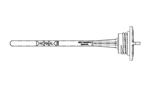
NOTE: If the oil and engine are not at operating
temperature, the oil level may read too low. Always make sure the engine is at operating temperature before checking the oil.
NOTE: Do not over-fill the oil tank or oil may be
pushed out through the breather hose.
14.Install the skid plate and access plate and secure with the torx-head screws; then close the hood.
Liquid Cooling System (3000/7000)
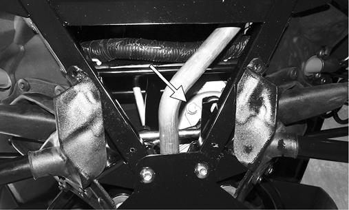
The liquid cooling system consists of a heat exchanger, water pump, and thermostat. The system should be inspected for leaks or damage whenever an overheating problem is experienced. DRAINING COOLING SYSTEM 3000 1.Remove both access panels; then remove the hood. 2.Remove the cap from the coolant filler neck; then using a coolant vacuum pump, remove as much coolant as possible from the neck. 3.Remove the five springs securing the resonator to the exhaust manifold; then disconnect the oxygen sensor.
Remove the resonator.

XM401A
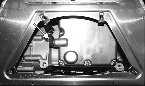
4.Position a funnel under the water pump and out through the exhaust hole in the skid plate; then remove the cap screw and let the coolant drain into a pan. Remove the coolant filler neck cap to allow all coolant to be removed from the system. Install the cap screw into the water pump. tighten to 96 in.-lb.
XM429A
5.Install the resonator using the existing springs; then connect the oxygen sensor. 7000 1.Open the hood; then remove both access panels. 2.Remove the cap from the coolant filler neck; then using a coolant vacuum pump, remove as much coolant as possible from the neck. 3.Remove the hose clamps securing the coolant hose to the filler neck and to the top of the radiator; then use the same vacuum to remove as much as possible from the radiator. FILLING/BLEEDING COOLING SYSTEM 1.With all hoses and hose clamps installed, add coolant into the filler neck until coolant is visible at the bottom of the neck; then add coolant to the coolant reservoir Full-Cold line.
CAUTION
The cooling system must be properly filled. If the system isn’t properly filled, engine damage will occur.
0747-547
2.Start the engine and allow it to run until the radiator fan turns on; then turn the engine off.
3.With the engine cool, remove the coolant cap and verify the coolant is at the full level. If the coolant is not at the full level, add coolant and repeat step 3 as necessary.
4.Close and latch the hood. INSPECTING COOLANT HOSES AND CLAMPS All coolant hoses and connections should be checked annually for deterioration, cracks, and wear. All coolant hoses and clamps should be replaced every four years.
INSPECTING THERMOSTAT 1.Inspect the thermostat for corrosion, wear, or spring damage. 2.Using the following procedure, inspect the thermostat for proper operation. A.Suspend the thermostat in a container filled with water; then heat the water and monitor the temperature with a thermometer. B.The thermostat should open at 75° C (167° F). Once the thermostat starts to open, and allow it to cool down verifying it has returned to the fully closed position.
CAUTION
Running the engine with low coolant level can cause severe engine damage.
CAUTION
Never heat the thermostat to the fully open position or damage to the thermostat may occur.
Cooling System Schematics
The following schematics are representative of the different styles of cooling systems in the Arctic Cat snowmobiles. Some components may vary from model to model; therefore, the technician should use discretion and sound judgment when servicing a particular cooling system.
3000
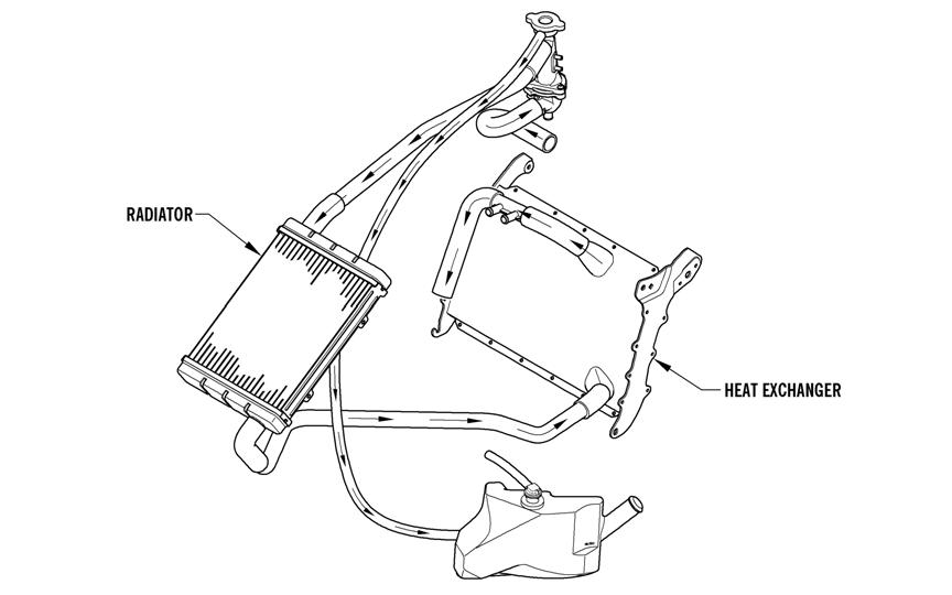
0749-693
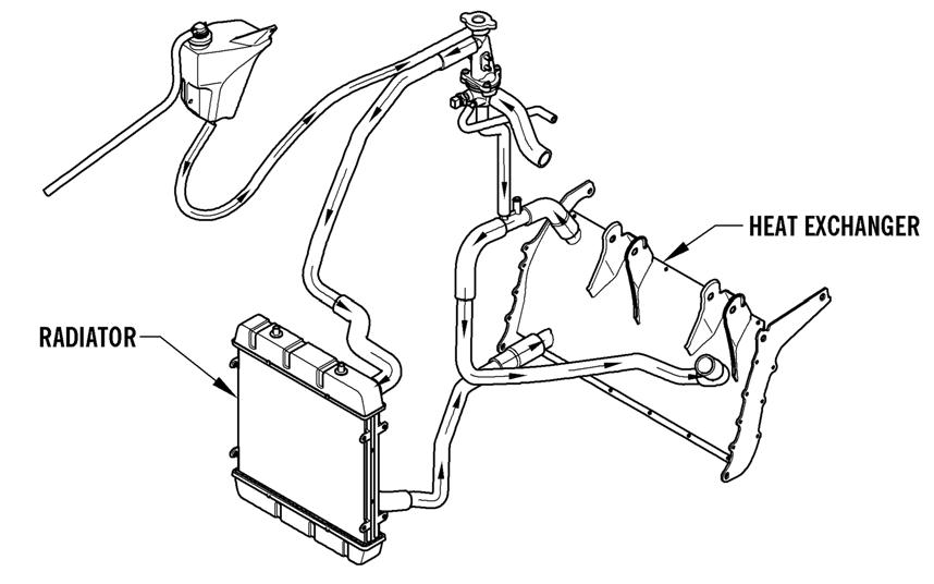
0749-712
Recoil Starter (2000)
KEY
A.Cap Screw
B.Roller
C.Friction Plate
D.Cap Screw
E.Pawl Activator
F.Pawl
G.Return Spring
H.Friction Plate Spring
I.Main Spring
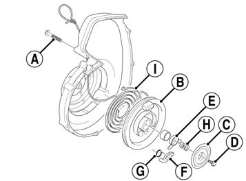
743-711A
REMOVING 1.Tie a slip-knot in the starter rope below the console and allow the rope to slowly retract against the starter case. 2.Remove the knot at the handle, remove the handle, and account for the handle cap; then thread the rope through the bushing in the console. 3.Remove the cap screws (A) securing the starter assembly to the magneto case; then remove the starter assembly.
DISASSEMBLING ! WARNING
Always wear safety glasses and gloves when servicing the recoil starter.
1.Secure the recoil starter in a vise.
2.Rotate the roller (B) counterclockwise until the notch of the roller is near the rope guide in the case. Guide the rope into the notch and slowly allow the roller to retract until all recoil spring tension is released.
3.While exerting downward pressure on the friction plate (C), remove the cap screw (D). 4.Slowly release the friction plate and lift the plate with pawl activator (E) free of the recoil roller; then remove the pawl activator from the friction plate. 5.Remove the pawl (F) and the return spring (G); then remove the friction plate spring (H). 6.Carefully lift the roller free of the case making sure the main spring (I) does not disengage from the case.
Account for the bushing.
! WARNING
During the disassembly procedure, continuous downward pressure must be exerted on the reel so it does not accidentally disengage and cause injury.
! WARNING
Care must be taken when allowing the recoil roller to unwind. Make sure all spring tension is released before continuing.
! WARNING
Care must be taken when lifting the roller free of the case.
7.Remove the main spring from the case by lifting the spring end up and out. Hold the remainder of the spring with thumbs and alternately release each thumb to allow the spring to gradually release from the case. NOTE: Do not remove the main spring unless
replacement is necessary. It should be visually inspected in place to save time.
8.Unwind the rope from the roller, untie the slip-knot, and remove the rope. CLEANING AND INSPECTING 1.Clean all recoil starter components. 2.Inspect springs and pawl for wear or damage. 3.Inspect the roller and case for cracks or damage. 4.Inspect the center hub for wear, cracks, or damage. 5.Inspect the rope for breaks or fraying. 6.Inspect the main spring for cracks, crystallization, or abnormal bends. 7.Inspect the handle for damage, cracks, or deterioration. ASSEMBLING 1.Hook the end of the main spring around the mounting lug in the case. 2.Insert the main spring into the case; then wind it in a counterclockwise direction until the complete spring is installed. NOTE: The main spring must seat evenly in the
recoil case.
3.Insert the rope through the hole in the roller and tie a knot in the end; then wrap the rope counterclockwise around the roller leaving approximately 20 in. of rope free of the roller. 4.Apply low-temperature grease to the main spring and hub. 5.Align the hook in the end of the main spring with the notch in the roller. 6.Carefully slide the roller over the hub and engage the spring with the roller; then install the bushing. 7.Install the return spring making sure the short leg of the spring is properly installed in the hole in the roller; then install the pawl making sure the return spring is properly positioned in the notch of the pawl. 8.Slide the end of the rope through the rope guide of the case; then tie a slip-knot in the rope. 9.Apply a low-temperature grease to the friction plate.
Place the pawl activator into position on the friction plate making sure the arms of the activator are properly positioned to the pawl. 10.Place the friction plate into position allowing it to rest on the friction plate spring; then install the cap screw (coated with blue Loctite #243) and thread the cap screw in until it contacts the friction plate. 11.Press down on the friction plate and tighten the cap screw to 48 in.-lb. 12.With 20 in. of rope exposed, hook the rope in the notch of the roller. 13.Rotate the roller four or five turns counter-clockwise; then release the rope from the notch and allow the rope to retract. 14.Pull the rope out two or three times to check for correct tension. NOTE: Increasing the rotations in step 13 will
increase spring tension.
INSTALLING 1.Place the starter assembly into position against the magneto case. 2.Secure the starter with cap screws (coated with blue
Loctite #243). Tighten to 60 in.-lb. NOTE: Before tightening the cap screws, slowly pull
the recoil rope until the pawl engages; then tighten the cap screws centering the recoil against the magneto case.
3.Thread the rope through the bushing in the console; then install the handle and secure with a knot. Seat the cap. 4.Release the slip-knot in the rope.
Air Silencer
2000 The air silencer is a specially designed component used to silence the incoming fresh air and also to catch the fuel that “spits back” out of the carburetors. The carburetors are calibrated with the air silencer in position; therefore, the engine must never be run with the air silencer removed. NOTE: To remove and install the air silencer, see
Engine section.
Cleaning and Inspecting 1.Check for holes or cracks in the silencer. 2.Periodically clean the silencer by removing the cover/tool tray assembly and vacuuming the interior of the silencer. 7000 Removing 1.Open the hood and remove both access panels; then disconnect the air temperature sensor connector and the three hoses from the air silencer. Loosen the three hose clamps securing the intake boots to the throttle body. Remove the air silencer and the intake boots.
BC245A
Installing 1.Install the air intake boots into the silencer; then position the assembly down into the engine compartment. 2.Install the intake boots onto the throttle body and secure using the existing clamps. Tighten securely. 3.Install the three hoses into the air silencer and connect the air temperature sensor. 4.Close and latch the hood.