39 minute read
Electrical Systems

All tests of the electrical components should be made using the digital Fluke Model 77 Multimeter. Replace any component that does not have a test value within specifications. NOTE: Whenever using a digital-style tester, “open (infinite resistance)” denotes an overload and the meter reading will be OL since the meter is not calibrated to register resistance values of that magnitude.
NOTE: Always check the appropriate fuse before testing a component for failure.
NOTE: Whenever a part is worn excessively, cracked, or damaged in any way, replacement is necessary. SPECIAL TOOLS A number of special tools must be available to the technician when servicing the electrical systems.
CATT II Description
Arctic Cat Diagnostic System Manual Laptop Diagnostic Tool Actuator Test Harness p/n
0544-023 2256-974 0744-048 0644-518
Fluke Model 77 Multimeter 0644-559
MaxiClips 0744-041 Throttle Position Sensor (TPS) Adjustment Tool Kit 3639-891
NOTE: Special tools are available from the Arctic Cat Service Parts Department.
Ignition System
NOTE: There must be 0.030-0.060 in. free-play between the throttle lever and the control housing.
741-518B TROUBLESHOOTING 1. Remove the spark plugs and visually check their condition. Replace any fouled plug. Attach the spark plugs to the high tension leads and ground them to the engine.
CAUTION
Do not ground the spark plug on the cylinder head cover. The cover is made of magnesium and any contact with spark or electrical arc will severely pit the surface. CAUTION
Before checking for spark, place all the engine switches in the deactivated position. In the event the engine could be flooded, engage the starter several times to clear the engine of excess fuel. CAUTION
Never crank the engine over without grounding the spark plugs. Damage to coils and/or CDI/ECM may result.
NOTE: Make sure the ignition switch and the emergency stop switch are in the ON position. 2. Crank the engine over and check for spark. If no spark is present, check to make sure the throttle cable is properly tensioned. Compress the throttle control and while holding the throttle control in this position, crank the engine over and check for spark. If spark is now present, adjust the throttle cable tension. TESTING Throttle Control Switch 1. Disconnect the handlebar harness connector; then connect the ohmmeter leads as shown below.
2. With the throttle lever in the idle position, the meter must read less than 1 ohm. If the meter reads OL (infinite resistance), replace the control assembly. 3. Move the throttle lever to the wide open position.
The meter must read OL (infinite resistance). If the meter reads less than 1000 ohms, replace the control assembly.
Green/Yellow Wire
Red/Green Wire
Throttle Position Sensor
VERIFYING TPS ADJUSTMENT TOOL Before using the TPS adjustment tool, verify its battery condition. The battery used in the tool is a 9-volt battery. To check battery condition, use a digital volt/ohmmeter set on DC volt scale. Test between the adjustment tool black and red jacks. Insert the red lead of the digital voltmeter into the red jack of the adjustment tool and the black lead of the digital voltmeter into the black jack of the adjustment tool. The green power light of the analyzer should now be illuminated. If voltage is found below 4.9 volts, replace the battery. NOTE: The Test Harness must be plugged into the analyzer for testing voltage. Always verify battery voltage is at least 4.9 DC volts before testing TPS.
CHECKING TPS NOTE: If the snowmobile is in warranty, breaking the seal on the idle screw jam nut or the Phillips-head screws on the TPS will void warranty. If the TPS is tested out of specification, the throttle body must be replaced. If the snowmobile is out of warranty, proceed to Adjusting TPS.
NOTE: On the 7000, the TPS should only be checked using the CATT II Tool. Instructions will be included with the tool.
1. Using Throttle Position Sensor (TPS) Adjustment
Tool Kit, connect its wiring harness to the TPS. 2. Connect the red tester lead to the white adjustment tool jack; then connect the black tester lead to the black adjustment tool jack. 3. With the throttle in the idle position, compare the reading on the voltmeter to the chart. If the reading is within prescribed specification, proceed to step 6.
Model Idle Full-Open 5000 1.10-1.14v 4.30-4.50v 9000 0.69-1.11v 4.00-4.20v
4. Compress the throttle lever slowly to the full-open position. The meter reading should show a smooth rise in voltage all the way to the full-open position. If the voltage seems to be erratic or doesn’t meet the prescribed specification, repeat this procedure several times to confirm results. NOTE: If at any point throughout the throttle range the meter reads no voltage (open), hold the throttle lever in that position. If the voltage does not return, the throttle body must be replaced. 5. If the full-open throttle voltage remains erratic or out of specification, proceed to the appropriate Adjusting
TPS. 6. If the TPS is within the prescribed specification, disconnect the adjustment tool harness from the TPS.
Connect the snowmobile TPS harness to the TPS. NOTE: Before installing the TPS harness connector, apply dielectric grease to the connector pins. ADJUSTING TPS NOTE: Adjusting the TPS is for out of warranty snowmobiles only.
NOTE: On the 7000, the TPS should only be adjusted using the CATT II Tool. Instructions are included with the tool.
NOTE: The throttle shaft must be against the throttle stop for this procedure.
CAUTION
Never adjust the throttle plate stop screw and nut. The idle circuit is controlled by the ISC valve.
1. Disconnect the harness connector from the TPS. 2. Loosen the screw(s) of the throttle position sensor to allow adjustment. 3. Using Throttle Position Sensor (TPS) Adjustment
Tool Kit, connect its wiring harness to the TPS. Connect the red and black digital voltmeter leads to the white and black jacks of the TPS adjustment tool. 4. While observing the digital voltmeter, slowly rotate the sensor until idle voltage specification is observed on the LCD of the multimeter. While holding the sensor in this position, tighten the screw(s) securing the sensor to the throttle body securely. 5. Gently snap the throttle open and closed several times to check the TPS voltage. If it has changed from the idle voltage specification, loosen the screw(s) securing the sensor and make necessary adjustments. 6. With the idle position set to specification, compress the throttle lever to the full-open position. The fullopen specification should be observed. Gently snap the throttle lever open and closed several times and note if the reading remains within the specification. NOTE: If, after adjusting the Throttle Position Sensor to the IDLE specification, the FULL-OPEN is less than 4.30 volts, recheck the IDLE setting. If the IDLE setting is correct, replace the sensor.
Model Idle Full-Open 5000 1.10-1.14v 4.30-4.50v 9000 0.69-1.11v 4.00-4.20v
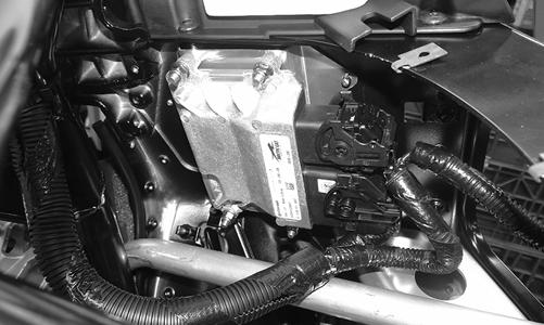
REPLACING TPS (5000/9000) NOTE: Replacing the TPS is for out of warranty snowmobiles only. Removing NOTE: On the 5000, remove the hood, seat, and gas tank. On the 9000, remove the hood, upper console, and lower console.
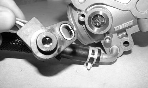
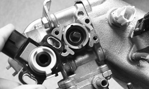
1. Disconnect the throttle cable from the throttle clutch. 2. Disconnect TPS wiring harness from the TPS; then noting the TPS position, remove the screw(s) securing TPS to the throttle body housing and remove the sensor. Account for the O-ring fitting into the groove of throttle body. Installing 1. Apply a light coat of silicone grease to the area around the outside of the TPS flange and into the Oring groove. Install the O-ring into the groove. 2. Install the new TPS onto the throttle shaft by aligning the “flats” on the throttle shaft cam with the alignment points of the sensor; then rotate the sensor until properly positioned on the throttle body.
9000
ZJ254
TZ119 3. Install the screw(s), flat washer(s), and lock washer(s) securing the sensor to the throttle body. Do not tighten at this time. 4. Adjust the TPS (see Adjusting TPS in this sub-section). 5. Disconnect the adjustment tool harness from the
TPS. Connect the snowmobile TPS harness to the newly installed or adjusted TPS. NOTE: Before installing the TPS harness connector, apply dielectric grease to the connector pins.
NOTE: On the 5000, install the gas tank, seat, and hood. On the 9000, install the lower console, upper console, and hood.
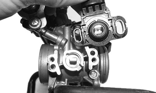
REPLACING TPS (7000) NOTE: Replacing the TPS is for out of warranty snowmobiles only. Removing 1. Remove the access panels, hood, air intake assembly. 2. Disconnect TPS wiring harness from the TPS; then noting the TPS position, remove the screws and washers securing TPS to the throttle body housing and remove the sensor. Installing 1. Install the new TPS onto the throttle shaft by aligning the “flats” on the throttle shaft cam with the alignment points of the sensor; then rotate the sensor until properly positioned on the throttle body.
YM-067 2. Install the screws w/ washers securing the sensor to the throttle body. Do not tighten at this time. 3. Adjust the TPS using the CATT II Tool. Instructions will be included with the tool. NOTE: Before installing the TPS harness connector, apply dielectric grease to the connector pins.
Electrical Resistance Tests (5000/9000)
NOTE: Replace any component that does not have a test value within specifications. If the component tests satisfactorily but is suspected to be faulty, connect the red meter lead to a component lead and the black meter lead to ground. Check for continuity between the component and ground. If continuity is observed, replace the component.
NOTE: The following test should be made using MaxiClips and the Fluke Model 77 Multimeter set to OHMS scale.
CAUTION
Always disconnect the battery when performing resistance tests to avoid damaging the multimeter.
Magneto Coil 1. Disconnect the white three-yellow-wire connector. 2. Connect the red meter lead to one yellow wire; then connect the black meter lead to another yellow wire (a total of three tests). 3. Resistance must be 0.2-0.4 ohm. Crankshaft Position Sensor 1. Disconnect the sensor. 2. Connect the red meter lead to the blue/white wire; then connect the black meter lead to the green/white wire. 3. Resistance must be 173-211 ohms. Ignition Coil 1. Disconnect an ignition coil connector. 2. Connect the red meter lead to the red/green wire; then connect the black meter lead to the gray/green (coil 1) or brown/green (coil 2) wire. 3. Resistance must be 1.4 ohms.
Injection Coil 1. Test between the black/yellow and black wires from the injection coil. 2. Resistance must be 3.6 ohms. Fuel Injector 1. Disconnect the fuel injector wiring harness. 2. Test between the two injector terminals. Resistance must be 9-12 ohms (5000) or 10.5-13 ohms (9000). Coolant Temperature Sensor 1. Disconnect the coolant temperature sensor wiring harness from the main harness. 2. Test the resistance between the two leads from the sensor. 3. Compare the resistance reading to the Voltage/Resistance Chart - Coolant Temperature in this section. Air Temperature Sensor NOTE: The component temperature must be known before conducting this test. Allow the engine to reach room temperature. 1. Disconnect the wiring harness from the air temperature sensor. 2. Set the meter selector in the OHMS position and test the sensor connector. Compare with the Voltage/
Resistance Chart - Air Temperature in this section. NOTE: The air temperature sensor utilizes a thermistor. Resistance will change as temperature varies.
Electrical Resistance Tests (7000)
NOTE: Replace any component that does not have a test value within specifications. If the component tests satisfactorily but is suspected to be faulty, connect the red meter lead to a component lead and the black meter lead to ground. Check for continuity between the component and ground. If continuity is observed, replace the component.
NOTE: The following test should be made using MaxiClips and the Fluke Model 77 Multimeter set to OHMS scale.
CAUTION
Always disconnect the battery when performing resistance tests to avoid damaging the multimeter.
Magneto Coil 1. Disconnect the three-white-wire connector. 2. Connect the red meter lead to one white wire; then connect the black meter lead to another white wire (a total of three tests). 3. Resistance must be 0.15-0.23 ohm. Crankshaft Position Sensor 1. Disconnect the sensor. 2. Connect the red meter lead to the gray wire; then connect the black meter lead to the black wire. 3. Resistance must be 336-504 ohms. Ignition Coil 1. Disconnect an ignition coil connector. 2. Connect the red meter lead to the orange wire; then connect the black meter lead to the other wire. 3. Resistance must be 1.19-1.61 ohms. Injection Coil (1) 1. Test between the red/blue and the red/black wires from the injection coil. 2. Resistance must be 86.4-105.6 ohms. Injection Coil (2) 1. Test between the red/blue and the green/black wires from the injection coil. 2. Resistance must be 86.4-105.6 ohms. Injection Coil (3) 1. Test between the red/blue and the blue/black wires from the injection coil. 2. Resistance must be 86.4-105.6 ohms. Fuel Injector 1. Disconnect the fuel injector wiring harness. 2. Test between the two injector terminals. Resistance must be 86.4-105.6 ohms. Coolant Temperature Sensor 1. Disconnect the coolant temperature sensor wiring harness from the main harness. 2. Test the resistance between the two leads from the sensor. 3. Compare the resistance reading to the Voltage/Resistance Chart - Coolant Temperature in this section. Air Temperature Sensor NOTE: The component temperature must be known before conducting this test. Allow the engine to reach room temperature. 1. Disconnect the wiring harness from the air temperature sensor. 2. Set the meter selector in the OHMS position and test the sensor connector. Compare with the Voltage/
Resistance Chart - Air Temperature in this section. NOTE: The air temperature sensor utilizes a thermistor. Resistance will change as temperature varies.
Voltage Regulator Tests
NOTE: The following test should be made using MaxiClips and the Fluke Model 77 Multimeter set to DC Volt scale.
This test should be made at the three-pin connector of the regulator/rectifier. ! WARNING
Most voltages generated by the ignition system are sufficient to interrupt pacemakers! All technicians, especially those using pacemakers, must avoid contact with all electrical connections after the engine has been started.
NOTE: Test the connector that comes from the engine. 1. Set the meter selector to the DC Voltage position. 2. Connect the red tester lead to the positive battery post; then connect the black tester lead to the negative battery post. 3. With the engine running at 2500-3000 RPM, the meter must show 12-14.5 DC volts. 4. Set the meter selector to the AC Voltage position. 5. Test between the three yellow wires for a total of three tests. 6. With the engine running at 2500-3000 RPM, all wire tests must be within 36-44 volts. NOTE: If tests failed, check all connections, etc., and test again. If no voltage is present, replace the stator assembly.
Testing Fuel Gauge Sender
NOTE: Before testing the sender, verify the harness from the sender to the gauge is satisfactory. 1. Remove the hood. 2. Disconnect the fuel gauge sender unit from the main wiring harness; then connect the ohmmeter leads to the two blue sender wires. 3. Compare the reading to the chart following.
Full <20 ohms 1/2 40-56 ohms Empty 76-105 ohms
Emergency Stop Switch
RESISTANCE 1. Remove the four torx-head cap screws securing the front/rear throttle control housing assembly to the handlebar. 2. Set the selector to the OHMS position. 3. Connect one tester lead to one pin; then connect the other tester lead to the other pin.
PC253A 4. With the switch in the OFF position, the meter must read OL (infinite resistance). 5. With the switch in the RUN position, the meter must read less than 1 ohm resistance. NOTE: If the meter does not show as specified, troubleshoot or replace the switch/component, the connector, or the switch wiring harness.
Starter Relay Solenoid
TESTING NOTE: The electric start solenoid may be tested using either one of the following methods. Method #1 1. Disconnect the solenoid connector from the main wiring harness. 2. Place the ohmmeter leads across the solenoid coil terminals. The ohmmeter must read 3-5 ohms. NOTE: An in-line ammeter would measure between 2 and 4 amps of solenoid coil current flow with the battery connected.
CAUTION
NEVER connect an in-line ammeter with the large starter cables because the 200 amps of current flow will instantly damage most ammeters.
Method #2 1. Using the multimeter set to the DC Voltage position, check the relay as follows. 2. Connect the red tester lead to the positive battery terminal; then connect the black tester lead to the starter cable connection on the starter relay. The meter must show battery voltage. NOTE: Engage the brake lever lock and place the emergency stop switch in the RUN position. 3. Engage the starter while observing the multimeter.
The multimeter should drop to 0 volts and a “click” should be heard from the relay. NOTE: If a “click” is heard and more than 1 volt is indicated by the multimeter, replace the starter relay. If no “click” is heard and the multimeter continues to indicate battery voltage, proceed to step 4.
4. Disconnect the two-wire plug from the starter relay; then connect the red tester lead to the green wire and the black tester lead to the black wire. 5. Depress the starter button and observe the multimeter. NOTE: If battery voltage is indicated, replace the starter relay. If no voltage is indicated, check fuse or relay.
Fuse
TESTING 1. Remove the fuse from the fuse holder. 2. Connect the ohmmeter across the fuse end-caps. 3. The ohmmeter must read less than 1 ohm of resistance.
Ignition Switch
TESTING
CAUTION
To prevent ohmmeter damage when testing circuits on snowmobiles equipped with an electric start, be sure to disconnect the battery before testing. 1. Disconnect the wiring harness from the ignition switch; then remove the switch from the console. 2. Using the ohmmeter, test the connections indicated in the following chart. If the meter reads more than one ohm of resistance between connected terminals or less than 1 ohm of resistance on non-connected terminals, the switch must be replaced.

746-246B
NOTE: If the ignition switch tests good, verify battery voltage to the harness side of the switch plug-in. If there is no voltage, troubleshoot the battery, switch fuse, or starter relay solenoid. If battery voltage is present at the plug-in and the starter fails to activate, use the following procedure: 1. With the ignition switch plugged in, place the emergency stop switch to the OFF position. 2. Connect the red tester lead to the black/yellow wire; then connect the black tester lead to a suitable ground. 3. Rotate the key to the START position and verify battery voltage. NOTE: If no battery voltage is present, troubleshoot the harness and/or the starter relay solenoid.
Starter Motor
REMOVING (5000/(9000) 1. Remove the driven clutch, seat, gas tank, throttle bodies, and intake flange; then remove the cap screw securing the upper portion of the left rear engine mount to the engine.
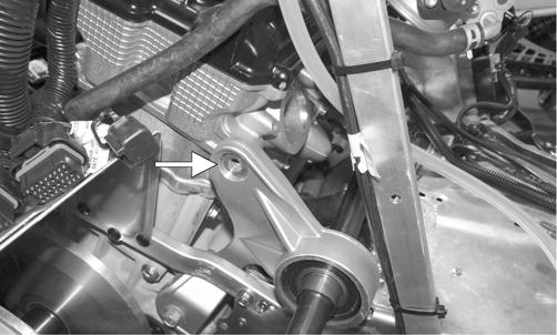
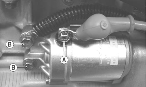
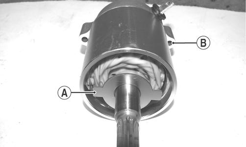
PC254A 2. Carefully pry on the engine enough to remove the starter motor; then remove the positive cable from the battery. 3. Remove cap screw (A) securing the positive cable to the starter motor; then remove the two cap screws (B) and remove the starter motor.
ZJ139A
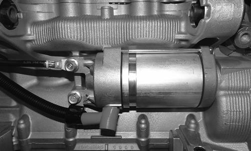
REMOVING (7000) 1. Remove the access panels, hood and the seat. 2. Remove the drive clutch, drive belt, driven clutch, gas tank, and air intake assembly; then remove the two cap screws and nuts securing the rear of the engine to the chassis. 3. Carefully pry the engine enough to remove the starter motor and battery cables from the engine.
YM-060
DISASSEMBLING (5000/9000) 1. Secure the starter motor in a suitable clamping device; then remove the two long cap screws from the starter motor.
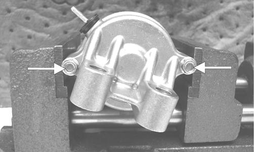
ZJ140A 2. For assembling purposes, make alignment marks on the bearing housing, magnet housing, and brush assembly.
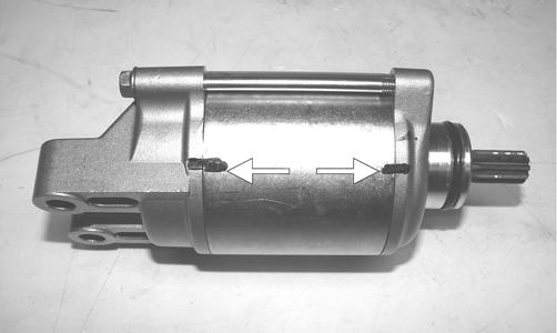
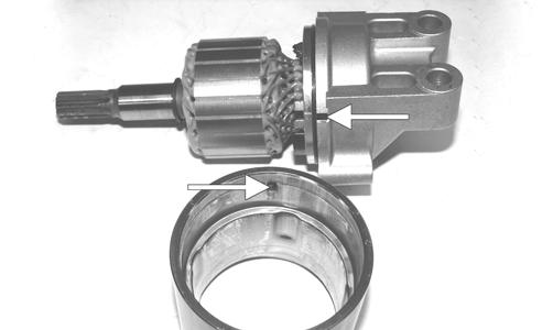
ZJ152A 3. Remove the bearing housing (A) and the magnet housing (B) with armature from the brush assembly (C).
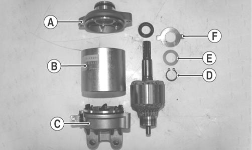
ZJ141A 4. With the armature removed from the magnet housing, remove snap ring (D) from the armature.
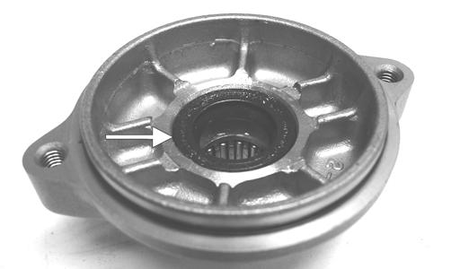
Account for shim (E) and locking plate (F). 5. Using a flat-blade screwdriver, carefully remove the seal from the bearing housing.
ZJ142A
CLEANING AND INSPECTING 1. Thoroughly clean all components except the armature and brushes in parts-cleaning solvent; then dry with compressed air.
2. Inspect all threaded areas for damaged or stripped threads. 3. Inspect the brush holder assembly and brushes for damage or wear. Using a caliper, measure the length of the brushes. If brush measurement is less than 0.40 in., replace with new brushes and brush springs as a set. 4. Inspect brush leads for cracks, wear, or fraying. If any of these conditions exist, replace with new brushes along with new brush springs as a set. 5. Inspect the rear cover bushing for wear. 6. Inspect the front cover bearing for wear.
CAUTION
Do not wash the armature and brushes in any kind of solvent. Use only compressed air and clean dry, lintfree cloth in cleaning these components.
7. Inspect the brass commutator end of the armature for any discolored spots or damage. If the commutator is slightly discolored or damaged, the armature must be replaced. This is a molded commutator and no attempt to turn it down in a lathe should be attempted.
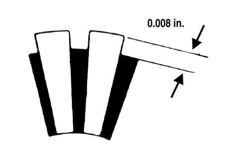
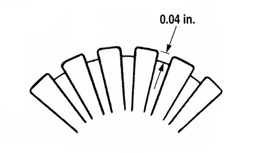
8. Inspect the commutator end of the armature for buildup in the grooves. Carefully remove any buildup by undercutting using a thinly ground hacksaw blade. Do not cut any deeper than the original groove which can be seen by looking at the end of the commutator. 9. Using a caliper, measure the undercut. Maximum undercut groove must be as shown.
CAUTION
Do not use emery cloth to clean the commutator as emery particles will become imbedded in the brass commutator resulting in a short circuit. Use only #200 grit sandpaper.
5000/9000
7000
SNO2171
SNO-382A
CAUTION
Buildup in the grooves must be removed to prevent any chance of an electrical arc between individual sections of the commutator.
10. Inspect the commutator for shorting using a multimeter and the following procedure.
A.Set the selector to the OHMS position.
B.Touch the black lead to the armature shaft.
C.Using the red tester lead, probe the commutator end of the armature. The meter indicator should not change. If the indicator shows resistance, the armature is shorted and must be replaced. 11. Inspect the armature for shorting using a “growler” and the following procedure.
A.Place the armature in the “growler.”
B.While holding a metal strip on the armature, rotate the armature an entire revolution. If the metal strip vibrates at any point on the armature, the armature is shorted and must be replaced.
0725-653 12. Inspect the ground brushes to make sure they are properly grounded. Use a multimeter and the following procedure.
A.Set the selector to the OHMS position.
B.Touch the black tester lead to a ground brush.
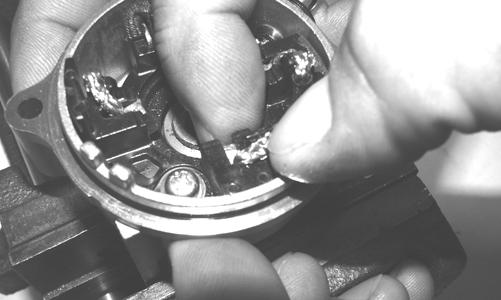
C.Touch the red tester lead to the brush holder assembly. NOTE: If no resistance is indicated, check the ground connection for tightness and for cleanliness. If there is still no meter indication, replace the brush assembly. ASSEMBLING 1. With the brush assembly secured in a vise, compress each brush all the way into the housing; then carefully push the brush wire over and down to secure the brush in the fully compressed position.
ZJ143
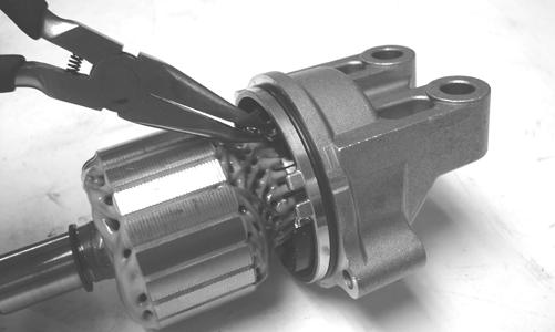
NOTE: The brushes must be fully compressed to allow enough room to install the armature. 2. Install the armature into the brush assembly; then using a small needle-nose pliers, carefully move the brush wires upward allowing the brushes to fully contact the commutator.
ZJ145
NOTE: After completing step 2, ensure that the brushes are properly seated to the commutator. 3. Noting the alignment marks made in disassembling, install the magnet housing; then with the magnet housing properly seated to the brush assembly, install the snap ring, shim, and locking plate to the armature shaft. NOTE: If alignment marks were not made during disassembling, align properly by matching notch on the magnet housing to notch on the brush assembly.
ZJ153A 4. With a suitable driving tool, install new seal into the bearing housing; then install the bearing housing. NOTE: Prior to installing the bearing housing, position the locking plate with the tabs (A) of the locking plate aligned with the cap screw ears (B) of the starter motor.
ZJ144A 5. Install the two long cap screws securing the starter motor together; then tighten the cap screws to 108 in.-lb.
ZJ140A
INSTALLING (7000) 1. Install the starter motor into the engine; then with the negative battery cable positioned to the top mounting hole, install the two cap screws (threads coated with blue Loctite #243) and tighten to 19 ft-lb. 2. Install the positive cable to the starter motor and tighten securely. Secure the positive and negative cables with cable ties as noted during disassembling.
YM-060 3. Secure the rear of the engine to the chassis using the existing cap screws and nuts Tighten to 50 ft-lb. 4. Install the air intake assembly, drive clutch, drive belt, driven clutch, gas tank, hood and access panels. 5. Install the positive cable to the battery; then install the seat. INSTALLING (5000/9000) 1. Install the starter motor to the engine; then with the ground cable positioned to the top mounting hole, install the two cap screws (B) and tighten to 19 ft-lb.
2. Install the positive cable (A) to the starter motor and tighten securely. Secure the positive and negative cables with cable ties as noted during disassembling. 3. Install the cap screw (threads coated with blue Loctite #243) securing the upper portion of the left rear engine mount to the engine; then install the intake flange, throttle bodies, driven clutch, gas tank, and seat. Tighten to 50 ft-lb. 4. Install the positive cable to the battery.
Troubleshooting Electric Start
Magneto
Problem: Hot or Smoking Wires Condition Remedy 1. System wired incor- 1.Check wiring against wirrectly ing diagram Problem: Starter Does Not Turn Over Condition Remedy 1. Battery discharged 1.Check/charge the battery 2. Connection loose 2.Check tightness of all connections 3. Grounding improper 3.Check ground connections 4. Fuse blown - not 4.Check - replace fuse installed
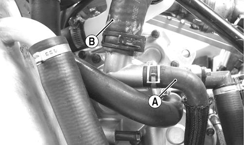
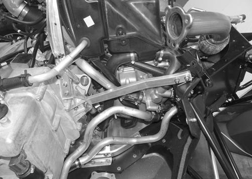
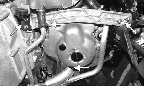
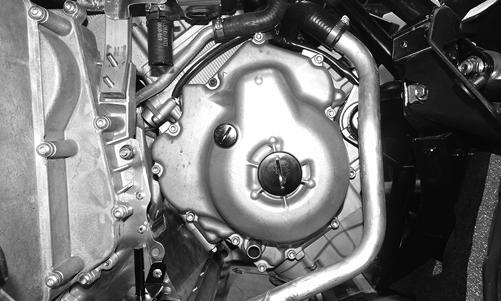
REMOVING (5000/9000) NOTE: Prior to removing the magneto, the engine oil and cooling system must be drained. 1. Disconnect the connector for the exhaust temperature sensor; then remove the cap screws, nuts, and springs securing the and resonator. 2. Remove the cap screws and nuts securing the MAGside chassis support; then remove all clamps and hoses to gain access to the magneto cover.
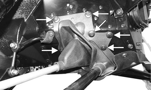
SNO-728 3. To gain access to the magneto cover, remove the remaining coolant hoses from the water pump, oil cooler, and separator tank. 4. Remove the eighteen cap screws securing the magneto cover to the engine; then remove the cover and account for the dowel pins, the oil pump seal, and the gasket.
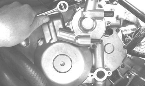
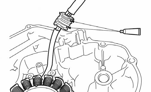
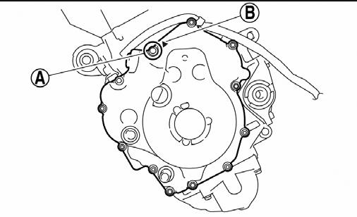
ZJ147 5. Remove the cap screws securing the harness clamp and timing sensor to the magneto cover.
ZJ148A 6. Remove the three cap screws securing the magneto to the cover; then remove the magneto assembly.
ZJ149A
INSTALLING (5000/9000) 1. Place the magneto into position on the cover; then install and tighten the three cap screws to 84 in.-lb.
With the harness routed properly, install the timing sensor and harness clamp and tighten to 84 in.-lb.
ZJ149A
ZJ148A 2. Install the two alignment pins in the engine for the magneto cover; then with a new gasket, install the cover and with the pattern shown, tighten the 18 cap screws to 84 in.-lb.
741-583A
NOTE: Assure the oil pump seal is in place prior to installing the magneto cover. 3. Install the coolant hoses to the water pump, oil cooler, and separator tank; then secure the hoses with the clamps. 4. Secure all coolant hoses and oil hoses using the existing clamps; then secure the left-side support using the existing cap screws and nuts. Tighten securely.

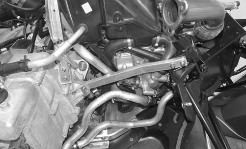
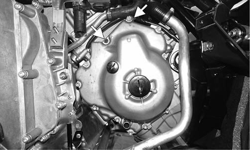
SNO-728 5. Install the resonator and secure using existing hardware. NOTE: At this point, fill and bleed the oil and cooling systems. REMOVING (7000) NOTE: Prior to removing the magneto, the engine oil and cooling system must be drained. 1. Disconnect the connector for the oxygen sensor; then remove the cap screws, nuts, and springs securing the and resonator. 2. Remove the cap screws and nuts securing the MAGside chassis support; then remove all clamps and hoses to gain access to the magneto cover.
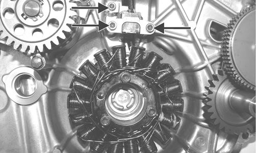
YM-055A 3. Remove the screws securing the magneto cover to the engine; then remove the cover and account for two dowel pins and the gasket. Disconnect the stator from the voltage regulator. NOTE: Note the location of the black screw and retaining clip as they must be installed in the same location as which they were removed.
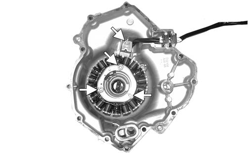
YM-056A 4. Remove the cap screws securing the harness clamp to the magneto cover. Remove the three cap screws securing the magneto to the cover; then remove the magneto assembly.
YM-057A
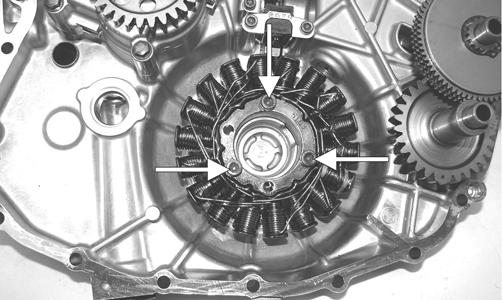
INSTALLING (7000) 1. Place the magneto into position on the cover; then install and tighten the three cap screws (threads coated with blue Loctite #243) to 7.2 ft-lb. With the harness routed properly, install the timing sensor and harness clamp and tighten (threads coated with blue
Loctite #243) to 7.2 ft-lb.
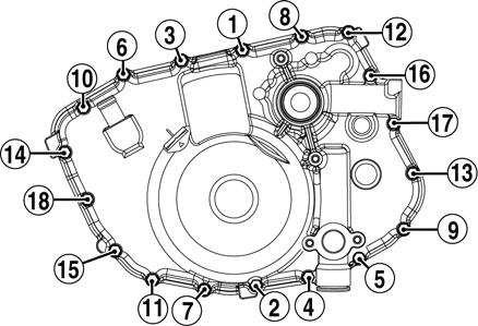
SNO-380 2. Install the two alignment pins in the engine for the magneto cover; then with a new gasket, install the cover and with a crisscross pattern, tighten the screws to 8.7 ft-lb.
YM-056
NOTE: The black screw (A) indicated by the black arrow (B) must have blue Loctite #243 applied to the threads. Tighten to 8.7 ft-lb.
YM-057A
NOTE: Be sure to apply a small amount of sealant to the grommet before pressing it into the cover.
SNO-381A 3. Secure all coolant hoses and oil hoses using the existing clamps; then secure the left-side support using the existing cap screws and nuts. Tighten securely.
YM-055A 4. Install the resonator and secure using existing hardware. NOTE: At this point, fill and bleed the oil and cooling systems.
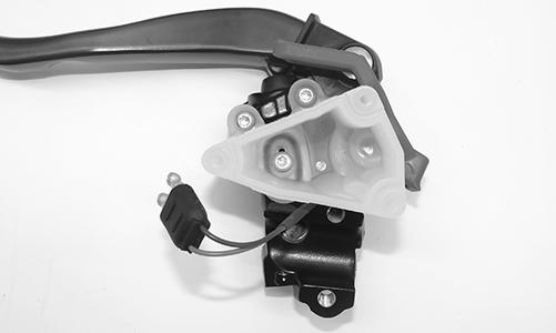
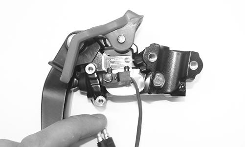
Brakelight Switch
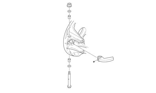
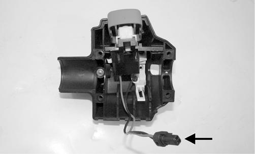
TESTING/REMOVING 1. Disconnect the brakelight switch grey and brown two-wire connector (located near the brake lever). 2. To test the brakelight switch, connect one tester lead to the brown terminal; then connect the other lead to the black terminal. 3. With the brake lever compressed, the meter must read 1 ohm or less resistance. With the brake lever released, the meter must read OL (open). If the meter does not read as specified, the brakelight switch is defective and must be replaced. 4. To remove the switch, remove all brake fluid from the reservoir; then remove the torx-head screws securing the reservoir to the piston assembly. Pry the brake switch from the piston assembly.
XM207 XM206
INSTALLING 1. Press the switch into the brake lever assembly making sure it is fully seated. 2. Position the O-ring into the reservoir; then secure the reservoir to the piston assembly using the existing screws. Tighten securely. 3. Connect the switch harness to the main wiring harness. Position the wires so they will not be either pinched or come in contact with any moving components. Start the engine and check the switch for proper operation.
Headlight Dimmer Switch
NOTE: At this point, remove the handlebar pad (if applicable). REMOVING/TESTING 1. Remove the four screws securing the left-side handlebar control assembly; then remove the control assembly from the handlebar. 2. Disconnect the HI/LO beam harness from the switch. 3. With the switch in the LO beam position, connect one ohmmeter lead to pin (A) and the other ohmmeter lead to pin (C). The meter must read 1 ohm or less resistance.
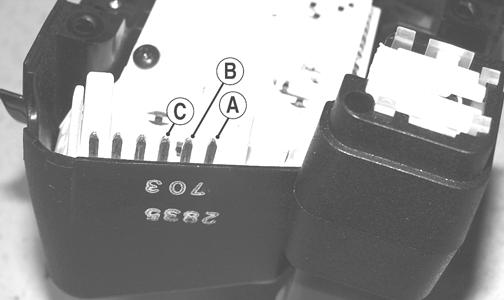
CM109A 4. With the switch in the HI beam position, connect one ohmmeter lead to pin (B) and the other ohmmeter lead to pin (C). The meter must read 1 ohm or less resistance.
NOTE: If either test does not read within specification, replace the complete control assembly. INSTALLING 1. Connect the HI/LO beam harness to the switch; then place the control assembly on the handlebar. 2. Secure with the four screws, then install the handlebar pad (if applicable).
Testing Handlebar Warmer Elements
NOTE: Resistance will vary due to temperature; therefore, this test should be made at room temperature of 20° C (68° F).
NOTE: To access the element connectors, the handlebar control assembly for the side being tested must be removed.
1. Remove the handlebar pad (if applicable); then disconnect the handlebar warmer three-wire connector. 2. In the element connector, connect one ohmmeter lead to the green/blue lead; then connect the other ohmmeter lead to the green lead. 3. The meter must read between 6.3-7.7 ohms. 4. In the element connector, connect the ohmmeter between the green/black and yellow lead wires. 5. The meter must read between 12.6 and 15.4 ohms. 6. Replace any element measuring less than or more than the specified amount. NOTE: Repeat test for the other element. 7. Connect the leads; then install the handlebar control assembly and secure the handlebar pad (if applicable).
Testing Thumb Warmer Element
NOTE: Resistance will vary due to temperature; therefore, this test should be made at room temperature of 20° C (68° F). 1. Remove the handlebar pad (if applicable); then disconnect the thumb warmer three-wire connector. 2. In the element connector, connect one ohmmeter lead to the green/blue lead; then connect the other ohmmeter lead to the green lead. 3. The meter must read between 1.5 and 6.9 ohms. 4. In the element connector, connect the ohmmeter between the green/black lead and the yellow lead. 5. The meter must read between 5.5 and 23.0 ohms. NOTE: If either test is not within specification, replace the thumb warmer element. 6. Connect the leads; then install and secure the handlebar pad (if applicable).
Testing Handlebar Warmer/Thumb Warmer Switch
REMOVING/TESTING 1. Remove the handlebar pad (if applicable). 2. Remove the four screws securing the left-side handlebar control assembly; then remove the control assembly from the handlebar. 3. Disconnect the handlebar/thumb warmer harness from the switch. 4. With the thumb warmer toggle in the low position, connect one ohmmeter lead to pin (C) and the other ohmmeter lead to pin (B). The meter must read 1 ohm or less resistance.
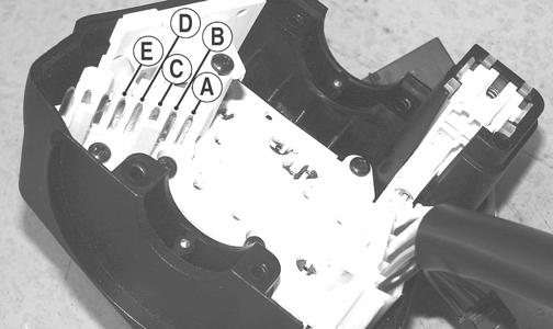
CM110A 5. With the thumb warmer toggle in the high position, connect one ohmmeter lead to pin (C) and the other ohmmeter lead to pin (A). The meter must read 1 ohm or less resistance. NOTE: If either test does not read within specification, replace the complete control assembly. 6. With the handwarmer toggle in the low position, connect one ohmmeter lead to pin (C) and the other ohmmeter lead to pin (D). The meter must read 1 ohm or less resistance. 7. With the handwarmer toggle in the high position, connect one ohmmeter lead to pin (C) and the other ohmmeter lead to pin (E). The meter must read 1 ohm or less resistance. NOTE: If either test does not read within specification, replace the complete control assembly. INSTALLING 1. Connect the handlebar/thumb warmer harness to the switch; then place the control assembly on the handlebar. 2. Secure with the four screws; then install the handlebar pad (if applicable).
Testing Seat Heater Switch
RESISTANCE 1. Disconnect the main harness/element connector. 2. Connect one ohmmeter lead to the red/yellow main harness wire; then connect the other ohmmeter lead to the green/red main harness wire. The meter must read the following ± 5%:
LO HI 4.32K ohms 3.75K ohms
NOTE: If resistance is not within specification, troubleshoot the switch connector located below the steering support. If the switch connector tests good, replace the switch. VOLTAGE 1. Disconnect the main harness/element connector. NOTE: For this procedure, test the main harness side of the connector, not the element side of the connector.
2. Connect one meter lead to the red/blue main harness wire; then connect the other meter lead to the black main harness wire. 3. Start the engine. The meter must read 12-15 volts. NOTE: If this voltage test does not read within specification, troubleshoot the main harness, F-2 fuse, K-2 relay, or the F-7 main fuse.
Testing Speedometer Sensor
NOTE: The following test should be made using MaxiClips and the Fluke Model 77 Multimeter set to the DC Volt scale.
NOTE: Prior to testing the sensor, inspect the threewire connector on the sensor harness for contamination, broken pins, and/or corrosion. With the engine running, note that a power supply of 10.8-14.4 DC volts exists at the main harness/speedometer connector.
PC067B 1. Elevate the rear of the snowmobile onto a suitable safety stand. 2. Set the meter selector to the DC Voltage position. 3. At the sensor side of the plug-in, connect the red maxiclip and meter lead to the white/orange lead; then connect the black maxiclip and meter lead to the black lead. 4. Connect a positive 12-volt DC power supply to the red/blue wire; then connect a negative cable to the black wire from the main harness side of the plug-in. 5. Rotate the driven clutch. The meter must read 0 volts and 12 volts alternately.
Testing Gear Position Switch
1. Disconnect the switch two-wire connector. 2. Connect one ohmmeter lead to one black wire; then connect the other ohmmeter lead to the other black wire. 3. With the reverse button pressed in, the meter must read less than 1 ohm of resistance. With the reverse button released, the meter must read OL (infinite resistance). NOTE: If the meter does not read as specified in either test, the switch is defective and must be replaced.
Testing Shift Switch
NOTE: The switch is located on the right-side handlebar control. To access the switch, the control assembly must be disassembled. 1. Disconnect the two-wire connector from the handlebar control. 2. Connect one ohmmeter lead to one pin; then connect the other ohmmeter lead to the other pin.
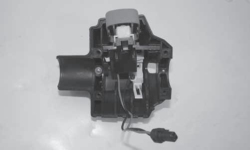
PC253B 3. With the reverse button pressed in, the meter must read less than 1 ohm of resistance. With the reverse button released, the meter must read OL (infinite resistance). NOTE: If the meter does not read as specified in either test, the switch is defective and must be replaced.
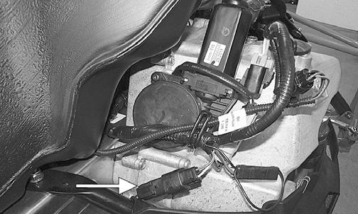
NOTE: The actuator is located on the chain case.
1. Disconnect the actuator two-wire connector; then connect Actuator Test Harness onto the harness side of the connector. 2. Connect one meter lead to the red/blue lead of the test harness; then connect the other meter lead to the yellow/orange wire lead of the test harness. 3. Press the reverse button; there should be a flash of
DC battery voltage indicated on the meter. Release the reverse button; then again press the reverse button; there should be a flash of DC battery voltage indicated on the meter. NOTE: If the meter indicates a flash of voltage but the actuator does not function, the actuator is defective and must be replaced.
NOTE: If the meter does not indicate a flash of voltage, troubleshoot the main harness.
Voltage/Resistance Chart - Air Temperature Voltage/Resistance Chart - Coolant Temperature
Temperature Volts Ohms Temperature Volts Ohms
100° C 212° F 0.113 555 28° C 82° F 1.230 8540 98° C 208° F 0.121 595 26° C 79° F 1.322 9530 96° C 205° F 0.128 635 24° C 75° F 1.413 10520 94° C 201° F 0.136 675 22° C 72° F 1.505 11510 92° C 198° F 0.143 715 20° C 68° F 1.596 12500 90° C 194° F 0.151 755 18° C 64° F 1.716 14020 88° C 190° F 0.162 819 16° C 61° F 1.836 15540 86° C 187° F 0.173 883 14° C 57° F 1.955 17060 84° C 183° F 0.184 947 12° C 54° F 2.075 18580 82° C 180° F 0.195 1011 10° C 50° F 2.195 20100 80° C 176° F 0.206 1075 8° C 46° F 2.323 23060 78° C 172° F 0.222 1160 6° C 43° F 2.452 26020 76° C 169° F 0.238 1245 4° C 39° F 2.580 28980 74° C 165° F 0.253 1330 2° C 36° F 2.709 31940 72° C 162° F 0.269 1415 0° C 32° F 2.837 34900 70° C 158° F 0.285 1500 -2° C 28° F 2.969 39940 68° C 154° F 0.308 1640 -4° C 25° F 3.101 44980 66° C 151° F 0.331 1780 -6° C 21° F 3.233 50020 64° C 147° F 0.353 1920 -8° C 18° F 3.365 55060 62° C 144° F 0.376 2060 -10° C 14° F 3.497 60100 60° C 140° F 0.399 2200 -12° C 10° F 3.610 76080 58° C 136° F 0.432 2410 -14° C 7° F 3.722 92060 56° C 133° F 0.465 2620 -16° C 3° F 3.835 108040 54° C 129° F 0.498 2830 -18° C -0.4° F 3.947 124020 52° C 126° F 0.531 3040 -20° C -4° F 4.060 140000 50° C 122° F 0.564 3250 -22° C -8° F 4.142 156000 48° C 118° F 0.612 3595 -24° C -11° F 4.224 172000 46° C 115° F 0.659 3940 -26° C -15° F 4.306 188000 44° C 111° F 0.707 4285 -28° C -18° F 4.388 204000 42° C 108° F 0.754 4630 -30° C -22° F 4.470 220000 40° C 104° F 0.802 4975 -32° C -26° F 4.522 261000 38° C 100° F 0.869 5490 -34° C -29° F 4.574 302000 36° C 97° F 0.937 6005 -36° C -32° F 4.625 343000 34° C 93° F 1.004 6520 -38° C -36° F 4.677 384000 32° C 90° F 1.072 7035 -40° C -40° F 4.729 425000 30° C 86° F 1.139 7550
Temperature Volts Ohms Temperature Volts Ohms
110° C 230° F 0.115 129 28° C 82° F 1.377 1800 108° C 226° F 0.129 137 26° C 79° F 1.459 1950 106° C 223° F 0.143 145 24° C 75° F 1.541 2100 104° C 219° F 0.157 153 22° C 72° F 1.623 2250 102° C 216° F 0.171 161 20° C 68° F 1.705 2400 100° C 212° F 0.185 169 18° C 64° F 1.806 2670 98° C 208° F 0.192 180 16° C 61° F 1.907 2940 96° C 205° F 0.199 191 14° C 57° F 2.008 3210 94° C 201° F 0.206 202 12° C 54° F 2.109 3480 92° C 198° F 0.213 213 10° C 50° F 2.210 3750 90° C 194° F 0.220 224 8° C 46° F 2.327 4170 88° C 190° F 0.235 240 6° C 43° F 2.444 4590 86° C 187° F 0.250 256 4° C 39° F 2.561 5010 84° C 183° F 0.265 273 2° C 36° F 2.678 5430 82° C 180° F 0.280 289 0° C 32° F 2.795 5850 80° C 176° F 0.295 305 -2° C 28° F 2.901 6510 78° C 172° F 0.317 327 -4° C 25° F 3.007 7170 76° C 169° F 0.339 349 -6° C 21° F 3.113 7830 74° C 165° F 0.361 371 -8° C 18° F 3.219 8490 72° C 162° F 0.383 393 -10° C 14° F 3.325 9150 70° C 158° F 0.405 415 -12° C 10° F 3.421 9422 68° C 154° F 0.438 445 -14° C 7° F 3.517 9694 66° C 151° F 0.471 475 -16° C 3° F 3.613 9966 64° C 147° F 0.504 505 -18° C -0.4° F 3.709 10238 62° C 144° F 0.537 535 -20° C -4° F 3.805 10510 60° C 140° F 0.570 565 -22° C -8° F 3.885 13688 58° C 136° F 0.598 609 -24° C -11° F 3.965 16866 56° C 133° F 0.626 653 -26° C -15° F 4.045 20044 54° C 129° F 0.654 697 -28° C -18° F 4.125 23222 52° C 126° F 0.682 741 -30° C -22° F 4.205 26400 50° C 122° F 0.710 785 -32° C -26° F 4.267 30520 48° C 118° F 0.759 849 -34° C -29° F 4.329 34640 46° C 115° F 0.808 913 -36° C -32° F 4.391 38760 44° C 111° F 0.857 977 -38° C -36° F 4.453 42880 42° C 108° F 0.906 1041 -40° C -40° F 4.515 47000 40° C 104° F 0.955 1105 -42° C -44° F 4.553 55100 38° C 100° F 1.023 1214 -44° C -47° F 4.591 63200 36° C 97° F 1.091 1323 -46° C -51° F 4.629 71300 34° C 93° F 1.159 1432 -48° C -54° F 4.667 79400 32° C 90° F 1.227 1541 -50° C -58° F 4.705 87500 30° C 86° F 1.295 1650