27 minute read
Engine-Related Items

NOTE: Whenever a part is worn excessively, cracked, or damaged in any way, replacement is necessary. SPECIAL TOOLS A number of special tools must be available to the technician when servicing the engine-related items.
Description
Blind-Hole Bearing Puller Coolant Cap Drive Clutch Spanner Wrench Valve and Spring Retainer Tool Fan Spanner Wrench Water Pump Bearing and Seal Tool Kit Oil Seal Protector Tool Engine Leak-Down Test Kit Vacuum Test Pump Hood Harness Extension Hood Harness Extension Oil Filter Wrench p/n
0644-500 0644-156 0644-136 0644-448 0644-340 0644-557 0644-219 0644-522 0644-131 1686-659 1686-660 0644-551
NOTE: Special tools are available from the Arctic Cat Service Parts Department.
Water Pump
! WARNING
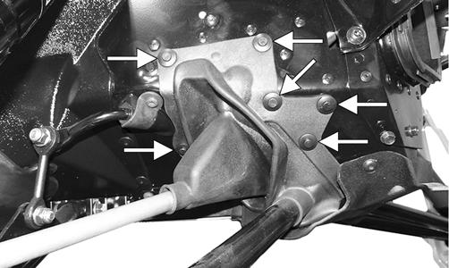
When servicing the water pump, disconnect the negative battery cable to avoid injury. REMOVING (5000/9000) 1. Drain the engine coolant (see Liquid Cooling System in this section). 2. Remove the water bypass hose (A); then remove the coolant tank/engine hose (B).
ZJ112A 3. Remove the separator tank breather hose to gain access to the water pump; then remove the water inlet hose from the water pump.
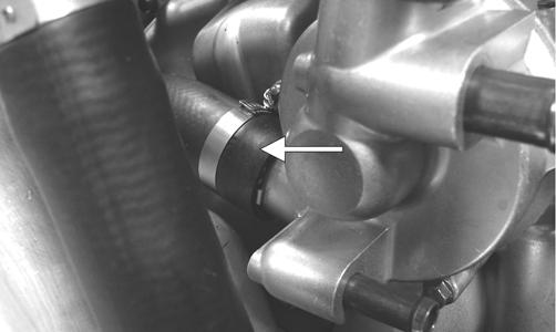
ZJ113A 4. Remove the two cap screws securing the water pump to the engine; then remove the pump and account for the O-ring.

ZJ114A
DISASSEMBLING/ASSEMBLING (5000/9000)
0742-104 1. Secure the water pump in a suitable support device; then remove the two Phillips-head screws (A) securing the inner/outer pump housings. 2. Separate the inner/outer pump housings; then remove the E-clip (B) from the impeller shaft, remove the shaft from the inner housing, and remove the ceramic seal (C) from the shaft. 3. With the inner housing secured in a suitable clamping device and using Blind-Hole Bearing Puller, remove the mechanical seal (D); then remove the oil seal (E).
CAUTION
Do not apply excessive heat to the housing or the bushing next to the bearing may be damaged.
4. Using the bearing puller, remove the bearing (F) from the inner housing. NOTE: Apply heat to the housing to aid in removing the bearing.

CAUTION
Do not apply excessive heat to the housing or the bushing next to the bearing may be damaged.
5. Clean the inner and outer housings with parts-cleaning solvent; then dry with compressed air. ! WARNING
Always wear safety glasses when drying components with compressed air. NOTE: For assembly, use Water Pump Bearing and Seal Tool Kit.
6. Using the appropriate-sized installation tool, install the bearing (F) into the inner housing. 7. Using the appropriate-sized installation tool, install the oil seal (E) with the spring side facing the bearing. 8. Place the mechanical seal (D) into the inner housing; then using the appropriate-sized installation tool, drive the seal into the housing until the lip of the seal is properly seated. 9. Install the ceramic seal (C) onto the impeller shaft with the ceramic face of the seal facing away from the impeller. 10. Install the impeller shaft into the inner housing and secure with the E-clip (B); then with a new O-ring properly positioned in the outer housing, place the water pump halves together. NOTE: Apply a light coat of grease on the O-ring to aid in keeping it properly positioned. 11. Secure the housings with the two Phillips-head screws (A); then tighten the screws with an impact driver.
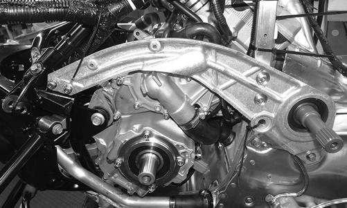
INSTALLING (5000/9000) 1. With a new O-ring (A) in place on the inner housing and the water pump shaft (B) properly aligned with the oil-feed pump shaft, install the water pump.
CAUTION
Care should be taken not to over-tighten the screws with the impact driver or damage to the housings may occur.
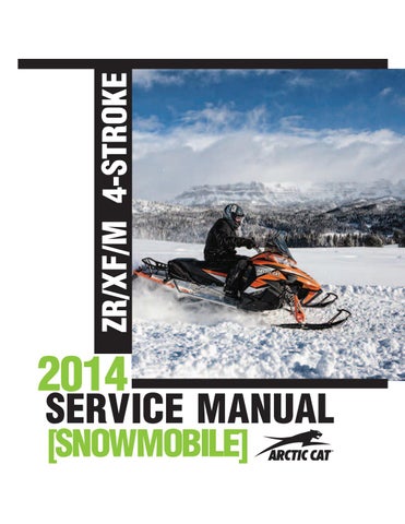
ZJ123A 2. With the water pump properly positioned, secure the pump with two cap screws and tighten to 84 in.-lb. 3. Install the water inlet hose and secure with the clamp; then install the separator tank breather hose and the remaining coolant hoses. Secure with the clamps. 4. Fill the cooling system (see Liquid Cooling System in this section). REMOVING (7000) 1. Drain the engine coolant. 2. Remove the drive clutch, drive belt, driven clutch and the clutch guard. 3. Remove the cap screws and nuts securing the leftside chassis support; then carefully tip the support up to gain clearance to the water pump.
YM-054 4. Disconnect all hoses from the water pump; then remove the allen-head screws securing the water pump assembly to the crankcase; then remove the assembly. Account for two dowel pins and two gaskets.


SNO-372 1. Obtain top-dead-center (TDC) by rotating the crankshaft (clockwise) until the mark on the magneto rotor is aligned with the pointer on the magneto cover and the #3 piston is at TDC.

SNO-279A 2. Remove the screws securing the water pump cover to the water pump; then remove the impeller. 3. Remove the water pump seal (A) from the water pump housing (B).

SNO-373A 4. Remove the bearing (A) and the oil seal (B) from the water pump housing (C).
SNO-374A 5. Remove the rubber damper holder (A) and the rubber damper (B) from the impeller using a small flat-head screwdriver making sure not to damage the impeller shaft.
SNO-375A
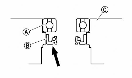
INSTALLING (7000) 1. Apply tap water or coolant to the outer surface of the new oil seal; then install the oil seal (A) into the water pump housing using a socket of the same diameter.
SNO-376A 2. Install the bearing using a socket of the same diameter; then apply sealant to the water pump housing; then install the water pump seal using the mechanical seal installation tool.
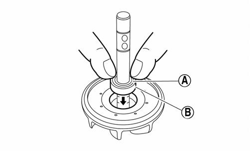
3. Apply tab water or coolant to the impeller shaft; then press the rubber damper holder (A) and rubber damper (B) onto the impeller shaft.
CAUTION
Never apply oil or grease onto the water pump seal surface.
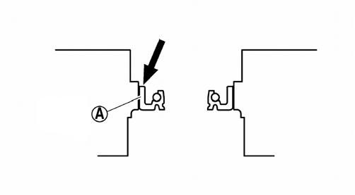
SNO-378A 4. Using a straight edge, make sure the impeller is flush with the damper.

SNO-379 5. Install the impeller assembly into the housing and secure using the existing circlip. 6. With the engine still at Top-Dead-Center (TDC), install the water pump and secure using the existing screws. Tighten to 8.7 ft-lb. 7. Fill the cooling system.
Pressure Testing Engine
NOTE: To pressure test the engine, use Engine Leak-Down Test Kit.
Checking Compression
NOTE: Prior to this test procedure, verify the battery is fully charged and the console is positioned over the support bracket with the hood/main harness plugged in.
NOTE: This test must be done with the engine at operating temperature and “full-cranking RPM” and the decompression system active. 5000/9000 With the spark plugs removed, install the compression tester gauge with adapter into the spark plug hole; then with the throttle valve in the full-open position, crank the engine over to get the psi reading. Compression should be 120 psi. 7000 With the spark plugs removed, install the compression tester gauge with adapter into the spark plug hole; then with the throttle valve in the full-open position, crank the engine over to get the psi reading. Compression should be 213.3 psi
CAUTION
Do not ground the spark plug on the cylinder head cover. The cover is made of magnesium and any contact with spark or electrical arc will severely pit the surface. NOTE: Verify both cylinder compression readings are within 10% of each other.
Changing Oil/Filter
5000/9000
! WARNING
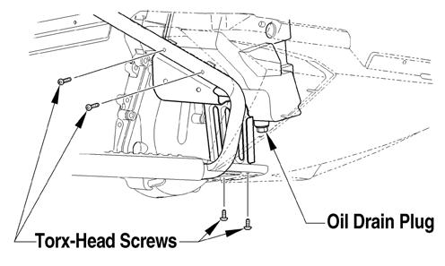
Care must be taken if a hot drain plug is removed by hand. Burning could occur. NOTE: For this procedure, disconnect the hood harness and the air intake connector from the air silencer; then remove the cables and pins securing the hood to the front end, remove the hood, and remove the access panels. 1. Park the snowmobile on a level surface; then start the engine and allow it to warm up for 5-10 minutes, or if the snowmobile was operated, allow the engine to idle for approximately 30 seconds. Shut the engine off. 2. Remove the torx-head screws and the access plate from beneath the snowmobile. 3. Place a drain pan beneath the engine oil pan drain plug; then remove the plug and allow the oil to drain completely.
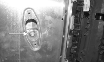
PC010A 4. Install the engine oil drain plug with a new gasket; then tighten the plug to 16 ft-lb. 5. Remove the four torx-head screws securing the rightside footrest to the tunnel and the support; then with a drain pan in position, remove the drain plug from the oil reservoir.
746-121A
NOTE: To aid in draining the oil from the reservoir, position a funnel between the reservoir and the opening of the tunnel running board. 6. After the oil has drained completely, install the drain plug with a new O-ring and tighten to 16 ft-lb. 7. Using Oil Filter Wrench, loosen (but do not remove) the oil filter and allow the oil to drain from the filter into the drain pan; then remove the filter. NOTE: On the 9000, the oil filter is accessible between the front opening of the chassis and the lower intercooler hose.
8. Apply a light coat of fresh engine oil to the seal of the new oil filter. 9. Install the new oil filter by turning the oil filter by hand until the seal has contacted the oil filter mounting surface; then tighten the oil filter to 15 ft-lb.
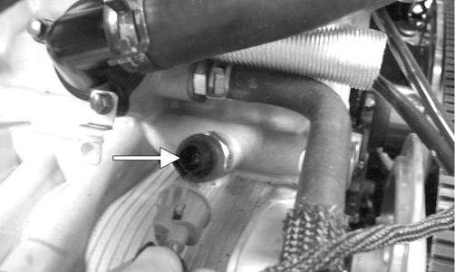
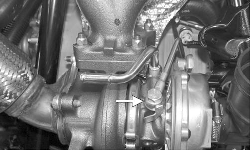
Remove the drain pan. 10. Pour 2.9 l (3 U.S. qt) of the recommended engine oil into the oil reservoir. 11. Open the air bleed bolt located on the oil pump (beneath the coolant tank) to purge air from the oil hose.

PC016A

NOTE: When air can no longer be heard purging from oil pump bleed, tighten the bleed bolt to 7.5 ft-lb.
CAUTION
Do not attempt to start the engine with the bleed bolt open. 12. Without starting the engine, place the handlebar emergency stop switch to the RUN position and the ignition switch to the ON position. The Oil Pressure
Warning Icon should illuminate immediately on the standard gauge or after the three seconds on the premium gauge. NOTE: If the warning icon does not illuminate, place the ignition switch in the OFF position and repeat step 11; then place the ignition switch in the ON position and repeat step 12. 13. If the warning icon illuminates (from step 12), start the engine. The warning icon should go out within five seconds. If it does, let the engine run for 5-10 minutes; then proceed to step 14. NOTE: If the warning icon does not go out, shut the engine off immediately and repeat step 11; then place the ignition switch to the ON position and repeat step 13.
14. Shut the engine off; then add oil to the oil reservoir until oil is visible halfway up in the sight glass. 15. Install the access plate and torx-head screws beneath the snowmobile; then install the hood and access panels. 7000
! WARNING
Care must be taken if a hot drain plug is removed by hand. Burning could occur. NOTE: Recycle or properly dispose of the used engine oil.
NOTE: The access panels and hood must be removed for this procedure. 1. Park the snowmobile on a level surface; then start the engine and allow it to warm up for 5-10 minutes, or if the snowmobile was operated, allow the engine to idle for approximately 30 seconds. Shut the engine off. 2. Remove the torx-head screws and the rear access plate from beneath the snowmobile. 3. Place a drain pan beneath the engine oil drain screw; then remove the screw and allow the oil to drain completely.
XM125A 4. Using Oil Filter Wrench (p/n 0644-551), loosen (but do not remove) the oil filter and allow the oil to drain from the filter into the drain pan; then remove the filter.
5. Apply a light coat of fresh engine oil to the seal of the new oil filter. 6. Install the new oil filter by turning the oil filter by hand until the seal has contacted the oil filter mounting surface; then tighten the oil filter to 12 ft-lb. 7. Install a new gasket and engine oil drain screw
Tighten the screw to 7.2 ft-lb. 8. Remove the four torx-head screws securing the rightside footrest to the tunnel and the support; then with a drain pan in position, remove the drain plug from the oil tank.
746-121A

NOTE: To aid in draining the oil from the reservoir, position a funnel between the tank and the opening of the tunnel running board. 9. After the oil has drained completely, install the drain plug with a new O-ring and tighten to 16 ft-lb. 10. Pour the recommended engine oil into the oil tank. 11. Without starting the engine, place the handlebar emergency stop switch to the RUN position and the ignition switch to the ON position. The Oil Pressure
Warning Icon should illuminate. NOTE: If the warning icon does not illuminate, take the snowmobile to an authorized Arctic Cat Snowmobile dealer for service. If not under warranty, this service is at the discretion and expense of the snowmobile owner.
12. If the warning icon illuminates (from step 11), start the engine. The warning icon should go out within five seconds. If it does, proceed to step 13. NOTE: If the warning icon does not go out, shut the engine off immediately and repeat step 11; then place the ignition switch to the ON position and repeat step 12. If the warning icon does not go out, take the snowmobile to an authorized Arctic Cat Snowmobile dealer for service. If not under warranty, this service is at the discretion and expense of the snowmobile owner.

13. Once the engine has reached operating temperature, shut the engine off; then add oil to the oil reservoir until oil is visible halfway up in the sight glass. NOTE: If the oil and engine are not at operating temperature, the oil level may read too low. Always make sure the engine is at operating temperature before checking the oil. 14. Install the access plate and torx-head screws beneath the snowmobile; then install the hood and access panels.
Testing Oil Pressure
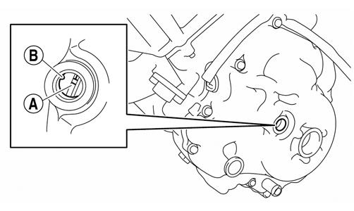
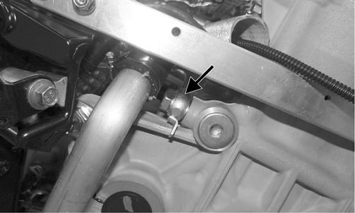
The Low Oil Pressure Warning Light indicates engine oil pressure, not the oil level; however, if the oil level is low, it may affect oil pressure. The light should illuminate each time the ignition switch is turned to RUN or START, and it should go out when the engine starts. If the light stays illuminated or it illuminates while the engine is running, oil pressure has been lost and the engine will automatically shut off. If oil pressure is lost, first verify oil level is correct. After adding oil, oil pressure should be normal. If not proceed to step 1. 1. On 5000 and 9000 models, locate the oil pressure sensor below the thermostat coolant hose; then disconnect the plug-in connector from the sensor.
5000
ZJ128B
9000
PC239A
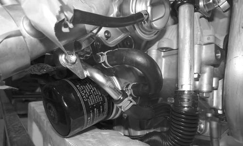
NOTE: On 7000 models, the sensor is located near the oil filter.
7000
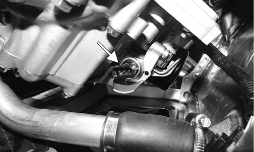
YM-065A 2. Remove the oil pressure sensor from the engine. 3. Using an oil pressure gauge and adapter, thread the adapter into the oil pressure sensor hole and tighten securely. 4. Start the engine, run at 4000 RPM, and observe the oil pressure. The engine oil pressure specification is 29 psi ± 20%. NOTE: This test must be done with the engine at running temperature. 5. After verifying oil pressure, remove the adapter and gauge from the engine, install the sensor, and tighten to 120 in.-lb. Start the engine and check for oil leaks. NOTE: Before installing the sensor, it may be necessary to apply thread sealant or teflon tape to the sensor threads.
CAUTION
Take care not to allow thread sealant or teflon tape into the oil passage or severe engine damage will occur.
Liquid Cooling System (5000/9000)
The liquid cooling system consists of a heat exchanger, water pump, and thermostat. The system should be inspected for leaks or damage whenever an overheating problem is experienced. DRAINING COOLING SYSTEM 1. Open the right-side access panel. 2. Remove the hardware securing the exhaust resonator; then remove the resonator. 3. Remove the hose clamp from the coolant hose connecting the water pump to the right side of the oil cooler. Clamp off the coolant hose; then with a drain pan positioned under the coolant hose, remove the hose from the water pump and tip the hose downward allowing the coolant to drain completely. 4. Apply 5-8 psi to the coolant system through the coolant overflow tube and continue until the coolant stops draining from the system. FILLING/BLEEDING COOLING SYSTEM 1. Remove the left- and right-side access panels and hood. NOTE: Place the hood along side the snowmobile; then using Hood Harness Extension, connect the hood to the main harness.
2. Loosen the bleed screw and add coolant into the filler neck until coolant is visible at the bleed screw; then tighten the bleed screw and add coolant to the coolant reservoir Full-Cold line.
CAUTION
The cooling system must be properly filled. If the system isn’t properly filled, engine damage will occur.

744-032A 3. Start the engine and allow it to run for five minutes. 4. With the engine cool, loosen the bleed screw and allow the coolant level in the filler neck to drop; then with the bleed screw loose, add coolant into the filler neck until no air is visible or heard at the bleed screw. Tighten the bleed screw and add coolant to the reservoir if necessary. NOTE: If the coolant level in the filler neck suddenly drops when the bleed screw is loosened, an air-lock occurred in the cylinder head. Add coolant to the filler neck until full before starting the engine.
CAUTION
Running the engine with low coolant level can cause severe engine damage.
5. Start the engine and allow it to run for five minutes; then shut the engine off and allow it to cool. 6. Repeat steps 5-6 at least two more times (more if necessary) until no air is in the cooling system.
CAUTION
Operating the snowmobile with air in the cooling system will cause severe damage to the engine. 7. Install the hood and both side panels. INSPECTING COOLANT HOSES AND CLAMPS All coolant hoses and connections should be checked annually for deterioration, cracks, and wear.
All coolant hoses and clamps should be replaced every four years. INSPECTING THERMOSTAT 1. Inspect the thermostat for corrosion, wear, or spring damage. 2. Using the following procedure, inspect the thermostat for proper operation.
A.Suspend the thermostat in a container filled with water; then heat the water and monitor the temperature with a thermometer.
B.The thermostat should open at 75° C (167° F). Once the thermostat starts to open, and allow it to cool down verifying it has returned to the fully closed position.
CAUTION
Never heat the thermostat to the fully open position or damage to the thermostat may occur.
Liquid Cooling System (7000)
The liquid cooling system consists of a heat exchanger, water pump, and thermostat. The system should be inspected for leaks or damage whenever an overheating problem is experienced. DRAINING COOLING SYSTEM 1. Remove both access panels and the hood. 2. Remove the cap from the coolant filler neck; then using a coolant vacuum pump, remove as much coolant as possible from the neck. 3. Remove the hose clamp securing the coolant hose to the bottom of the radiator; then remove the hose and pour coolant into a container. Using the same vacuum pump, remove coolant from the heat exchangerto-radiator hose until all coolant is removed from the snowmobile. FILLING/BLEEDING COOLING SYSTEM
NOTE: Place the hood along side the snowmobile; then using Hood Harness Extension, connect the hood to the main harness.
1. With all hoses and hose clamps installed, add coolant into the filler neck until coolant is visible at the bottom of the neck; then add coolant to the coolant reservoir Full-Cold line.
CAUTION
The cooling system must be properly filled. If the system isn’t properly filled, engine damage will occur.
0747-547
0747-766 2. Start the engine and allow it to run until the radiator fan turns on; then turn the engine off. 3. With the engine cool, remove the coolant cap and verify the coolant is at the full level. If the coolant is not at the full level, add coolant and repeat step 3 as necessary.
4. Install the hood and both side panels. INSPECTING COOLANT HOSES AND CLAMPS All coolant hoses and connections should be checked annually for deterioration, cracks, and wear. All coolant hoses and clamps should be replaced every four years. INSPECTING THERMOSTAT 1. Inspect the thermostat for corrosion, wear, or spring damage. 2. Using the following procedure, inspect the thermostat for proper operation.
A.Suspend the thermostat in a container filled with water; then heat the water and monitor the temperature with a thermometer.
CAUTION
Running the engine with low coolant level can cause severe engine damage.
B.The thermostat should open at 75° C (167° F).
Once the thermostat starts to open, and allow it to cool down verifying it has returned to the fully closed position.
CAUTION
Never heat the thermostat to the fully open position or damage to the thermostat may occur.
Cooling System Schematics
The following schematics are representative of the different styles of cooling systems in the Arctic Cat snowmobiles.
5000
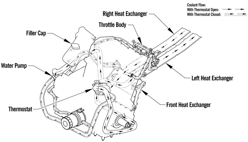
0746-354
7000
0746-522
0747-953
REMOVING/INSTALLING 1. Remove the right- and left-side access panels; then disconnect the hood harness and remove the hood. 2. Remove the seat and gas tank (see the Fuel Systems section). 3. Loosen both clamps securing the air silencer to the throttle bodies; then remove the air silencer assembly. 4. Install the air silencer assembly and secure to the throttle bodies using the clamps. 5. Install the gas tank (see the Fuel Systems section) and seat. 6. Install the hood, connect the hood harness, and install both access panels.
Air Silencer (7000)
REMOVING/INSTALLING 1. Remove the right- left-side access panels; then disconnect the hood harness and remove the hood. 2. Remove the two screws securing the radiator holddown-bracket to the air intake; then move the radiator out of the way and remove the two screws securing the front of the air intake to the chassis. Account for a coolant hose routing clamp. 3. Loosen all three hose clamps securing the intake boots to the throttle body; then disconnect the air temp sensor. Remove the air intake assembly.

YM-036 4. Install the air silencer assembly and secure to the throttle bodies using the clamps; then secure the front of the air intake to the chassis using the two screws and the routing clamp. Tighten securely. 5. Install the hood, connect the hood harness, and install both access panels. REMOVING/INSPECTING 1. Remove the air cleaner cover; then remove the air filter. 2. Inspect the filter for tears or dirt and replace if necessary. Clean any debris from inside the air intake plenum.
INSTALLING Place the air filter into position into the plenum; then secure the air cleaner cover onto the plenum.
CAUTION
Do not use compressed air to clean the filter. Damage to the filter may occur. CAUTION
A torn air filter can cause damage to the turbocharger/ engine. Contaminants may get inside the turbocharger/engine if the filter is torn. Carefully examine the filter for holes or tears. Replace the filter with a new one if torn.
CAUTION
Do not run the engine without the air filter installed. Severe damage to the turbocharger/engine will occur.
Turbocharger/Intercooler (9000)
! WARNING
The rotating components in a turbocharger turn at speeds of 150,000 RPM. Any imbalance could cause rapid disintegration resulting in bodily injury or death. Always handle a turbocharger in accordance with the manufacturer’s recommendations.
CAUTION
Do not drop the turbocharger. If dropped, it must be replaced.
CAUTION
Do not touch rotating parts as damage to turbine or compressor blades may occur.
Do not carry the turbocharger by the hoses or by the waste gate control rod. Damage could occur. CAUTION
Do not run a turbocharged engine with the intake hose removed from the compressor inlet. Dirt, foreign objects, or loose clothing can be ingested causing turbocharger failure and engine damage. CAUTION
Do not spin the turbocharger with compressed air as bearings will be damaged. CAUTION
Do not store the turbocharger vertically as oil will be lost from the bearing cavity and bearing damage on start-up could occur. REMOVING 1. Remove the right- and left-side panels; then remove the hood. 2. Disconnect the oxygen sensor; then remove the cap screws, nuts, gasket, and spring securing the resonator. Remove the resonator.
PC227
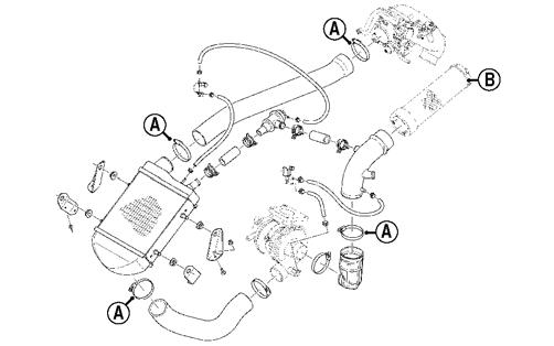
NOTE: Be sure to mark all hoses to the corresponding locations for installation purposes. 3. Remove all clamps (A) securing the outlet hose, air duct, and intercooler; then remove the air filter (B) and all hoses connected to the intercooler.
SNO-231A 4. Remove the intercooler, air bypass valve, and air duct as an assembly by removing the intercooler from the four mounting brackets. 5. Remove the clamp securing the coolant return hose (A); then remove the five torx-head screws securing the front heat shield.

PC229A
CAUTION
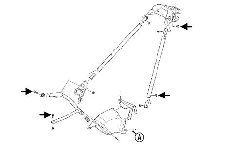
If the turbocharger is not being replaced during this procedure, close off the inlet and outlet of the turbocharger to avoid any objects entering the turbocharger. 6. Remove the torx-head screws securing the front leftside facia to the chassis. 7. Remove the cap screws securing the left-side front spar to the chassis; then remove the two cap screws and nuts securing shock mount support bracket.
Remove the rear heat shield, front spar, and shock mount.
SNO-232A
NOTE: To aid in the removal of the assembly from step 6, drill out the rivet (A) securing the rear heat shield to the left spar tube. 8. Remove the banjo bolts with four crush washers securing the oil feed pipe to the turbocharger and to the engine. Discard the washers.
PC230A
PC233A 9. Place a shop towel under the coolant feed hose and oil return hose; then using a suitable clamping device, clamp off the coolant hose. Loosen the hose clamps and disconnect the hoses from the 9000.
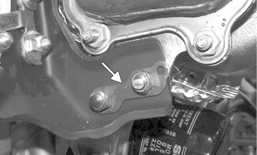
PC236 10. Remove the three lock nuts and washers securing the bracket of the turbocharger to the engine; then loosen the lock nuts securing the mounting bracket to the turbocharger.
PC234A
NOTE: If the oil hose has to be removed from the engine, note the banjo bolt securing the hose to the turbocharger has the smaller feed holes. 11. Remove the lock nuts and washers securing the exhaust manifold to the cylinder head; then carefully remove the turbocharger and exhaust manifold assembly. 12. Remove the cap screws securing the lower heat shield to the exhaust manifold and turbocharger; then remove the mounting bracket. 13. Remove the lock nuts securing the turbocharger outlet; then remove the turbocharger outlet from the turbocharger and account for the gasket. 14. Remove the four lock nuts securing the turbocharger to the exhaust manifold. Account for the gasket and flat washers. INSPECTING 1. With the exhaust pipe removed, inspect the turbine (exhaust) blades for any signs of wear or damage; then inspect the compressor (intake) blades. NOTE: If any damage to the compressor or turbine blades is present, the turbocharger must be replaced.
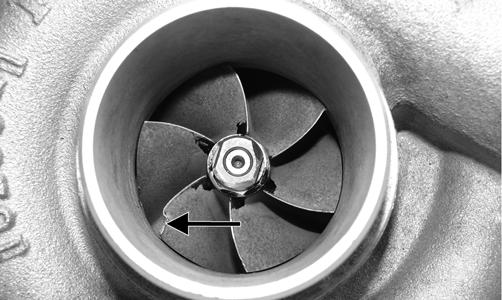
TZ093A 2. Inspect the waste gate linkage for signs of wear or damage. INSTALLING 1. With the turbocharger secured in a suitable vise and the gasket in place, secure the exhaust pipe to the turbocharger with the washers and lock nuts. Tighten the lock nuts to 15 ft-lb.
2. Install the mounting bracket to the 9000; then with the backing plate properly positioned as shown, secure the bracket to the turbocharger with the lock nuts and finger tighten only.
PC235A 3. With the gasket in place, install the turbocharger onto the exhaust manifold and secure with the flat washers and lock nuts. Tighten only until snug. 4. Install the lower heat shield onto the turbocharger and exhaust manifold with the four cap screws.
Tighten to 56 in.-lb. 5. With the gaskets in place, install the exhaust manifold and turbocharger assembly to the engine; then tighten the exhaust manifold to 15 ft-lb.
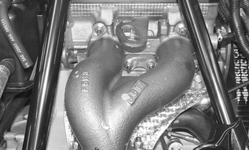
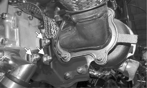
PC231 6. Install the three lock nuts securing the turbocharger mounting bracket to the engine. Tighten the nuts to 30 ft-lb and bend each tab to secure the nut.
PC234A 7. Tighten the two lock nuts (from step 2) to 30 ft-lb. 8. Using a crisscross pattern, tighten the lock nuts (from step 3) securing the turbocharger to the exhaust manifold to 30 ft-lb. 9. Connect the coolant feed hose and oil return hose to the 9000, release the clamp, and secure the hoses with the hose clamps.
PC236 10. With the turbocharger secured, connect the oil feed hose with both banjo bolts and four new crush washers. Tighten to 11 ft-lb.
PC230A
PC233A 11. Secure the left-side front spar to the chassis; then install the two cap screws and nuts securing shock mount support bracket. Install rivet (A) through the heat shield and into the left-side spar. Tighten cap screws to 23 ft-lb.
SNO-232A 12. Install the inlet boot and the inlet hose and secure using the existing clamps.
SNO-233 13. Secure the front left-side facia to the chassis using the existing torx-head screws. 14. Secure the front heat shield using the existing torxhead screws; then secure the coolant return hose (A).
PC229A 15. Install the intercooler, air bypass valve, and the air duct as an assembly into the four mounting brackets. 16. Secure the outlet hose, air duct, and intercooler using the existing clamps (A); then install the air filter (B) and all hoses connected to the intercooler.
SNO-231A 17. Connect the oxygen sensor; then install the cap screws, nuts, new gasket, and spring securing the resonator to the chassis.
PC227
NOTE: Check the coolant level and the oil level. Add as necessary (see the Fuel Systems section). 18. Install the right- and left-side panels; then install the hood.