44 minute read
Drive Train/Track/Brake Systems

This section has been organized into sub-sections for servicing drive train, track, and brake systems; however, some components may vary from model to model. The technician should use discretion and sound judgment when removing and installing components. NOTE: Whenever a part is worn excessively, cracked, or damaged in any way, replacement is necessary. SPECIAL TOOLS A number of special tools must be available to the technician when servicing the drive train, track, and brake systems.
Description p/n
Drive Clutch Bolt Tool 0644-281 Driven Shaft Bearing Spanner Wrench Kit - Socket 0644-516 Bearing Removal and Installation Tool 0644-167 Movable Sheave Bearing Tool 0644-594 Brake Disc Socket Wrench 0644-481 Clutch Alignment Bar 0644-428 Drive Clutch Puller 0744-062 Drive Clutch Spanner Wrench 0644-136 Driven Clutch Compressor Tool 0644-444 Driven Clutch Puller 0644-469 Clutch Alignment Bar (Parallelism) 0644-509 Rear Suspension Spring Tool 0144-311 Reverse Gear Adjustment Gauge 0644-244 Roller Pin Removal Tool 0644-276 Gear Case Drain Fitting 0644-552 Deep Socket 0444-237 Brake Caliper Bearing Puller 0744-067
NOTE: Special tools are available from the Arctic Cat Service Parts Department.
CAUTION
Never attempt to substitute any other drive clutch puller for the recommended puller or severe clutch damage will occur.
Drive Belt
If the drive belt is longer than specified, the drive clutch and driven clutch will not achieve full shift ratio. This will result in poor acceleration and a decrease in top speed. If the drive belt is shorter than specified, the starting ratio will be higher causing the belt to slip. A too-short drive belt will cause a bog on engagement and will not allow the engine to reach peak RPM. NOTE: A thinly-worn drive belt may produce the same effect as one that is too long.
NOTE: A stiff belt causes a HP loss to the track. As a belt warms up, it gets more flexible and transmits power with less HP loss. REMOVING 1. With the engine off, open the left-side access panel; then remove the belt guard. Loosen the quarter turn screws on the lower console. 2. Remove the cap screw, lock washer and sheave adjuster from the end of the driven clutch; then remove the cap screw, lock washer, and washer from the adjuster. NOTE: Ensure the shims and O-ring are not removed from the adjuster.
0743-395 3. Reverse the adjuster and install the cap screw without washers into the adjuster. Install the sheave adjuster and cap screw onto the driven clutch; then tighten the cap screw until the movable sheave opens far enough to allow the belt to be removed. 4. Remove the drive belt from the driven clutch first; then from the drive clutch. INSTALLING NOTE: When installing a new drive belt, see After Break-In Checkup - Drive Belt Break-In in the General Information section.
1. Place the drive belt (so the arrow is pointing toward the front of the snowmobile) on the drive clutch; then between the sheaves of the driven clutch. 2. Install the sheave adjuster in its original position (beveled side out); then install the cap screw, lock washer, and washer into the driven clutch. Tighten the cap screw to 20 ft-lb.
3. Install the belt guard; then close the left-side access panel. CAUTION
Do not apply Loctite to the driven clutch cap screw or component damage may occur.
! WARNING
Never operate the snowmobile without the belt guard/ access panel secured in place.
CHANGING CAM ARMS/SPRINGS Removing 1. Using Drive Clutch Bolt Tool, remove the torx-head screw and lock washer securing the drive clutch to the crankshaft.
NOTE: Before installing the clutch puller, apply oil to the threads of the puller and a small amount of grease to the tip of the puller.
2. Using the Drive Clutch Puller and the Drive Clutch
Spanner Wrench, tighten the puller. If the drive clutch will not release, sharply strike the head of the puller. Repeat this step until the clutch releases. 3. Remove the drive clutch and drive belt from the engine compartment. Disassembling NOTE: Note the timing marks on the cover, spider, and movable sheave. These must be aligned when assembling the drive clutch for balance purposes.
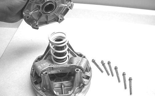
1. Loosen the screws securing the cover. Remove every other cap screw and lock washer from the cover; then while firmly holding the cover, remove the three remaining screws and lock washers equally. 2. Remove the cover and spring.
FC055 3. Remove the cam arm pin lock nuts; then using a small torch, apply heat to the cam arm set screws to loosen the Loctite used in assembly.
FS001
NOTE: Heat must be applied to the cam arm in order to remove the set screws.
4. After the set screws have been removed, remove the cam arm pins one at a time noting the position of the alignment notches in the cap screws for assembly purposes. Account for both O-rings.
0739-038
Cleaning and Inspecting 1. Using parts-cleaning solvent, wash grease, dirt, and foreign matter off all components; dry with compressed air.
2. Remove any drive belt dust accumulation from the stationary sheave, movable sheave, and bushings using parts-cleaning solvent only. 3. Inspect stationary sheave, movable sheave, spider, and cover for cracks or imperfections in the casting. 4. Inspect the cam arm pins for wear or bends. 5. Inspect the spring for distortion, cracks, or wear. 6. Inspect rollers for damage or wear. Assembling 1. With the head of each cam arm pin positioned towards the direction of the drive clutch rotation, install the cam arms.
! WARNING
Always wear safety glasses when using compressed air to dry components.
2. With the cam arm pin properly positioned, apply green Loctite #620 to the set screw holes in the cam arm, install the new set screws (pre-coated with Loctite), and tighten to 19 in.-lb.
739-040B
CAUTION
Green Loctite #620 must be applied to the set screw holes in the cam arms or component damage may occur. 3. Secure the cam arm pins with new lock nuts and tighten to 11 ft-lb.
4. Place the spring and cover into position making sure the timing mark on the cover is properly aligned; then compress the spring and install the screws coated with blue Loctite #243 and lock washers. In a crisscross pattern, tighten evenly to 120 in.-lb.
CAUTION
When installing cam arms, always use new lock nuts and cam arm set screws.
XM009A
CAUTION
Care must be taken when installing the cover not to damage the bushing.
Installing NOTE: Before installing the drive clutch, be sure to wipe both the crankshaft taper and clutch mounting taper clean using a clean towel.
1. Place the drive clutch into position on the crankshaft; then apply a few drops of oil to the threads of the cap screw. 2. Using Drive Clutch Spanner Wrench to hold the drive clutch, secure using the cap screw and high collar washer. Tighten to 51 ft-lb.
CAUTION
When installing the drive clutch, do not tighten the cap screw with any kind of impact tool. Tighten cap screw using a hand torque wrench only. Failure to do so could result in stationary sheave damage. 3. Check alignment between the drive clutch and driven clutch. 4. Install the drive belt. Check drive belt deflection.
Close the left-side access panel. NOTE: For installing drive belt, see Drive Belt in this section.
! WARNING
Never operate the engine without the belt guard/ access panel secured.
5. Either test drive the snowmobile or run the engine for five minutes; then verify the drive clutch cap screw torque specification.
Driven Clutch
REMOVING 1. Remove the drive belt. 2. Slide the driven clutch off the shaft.
NOTE: Account for any alignment washers. These washers must be in place during installation.
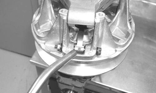
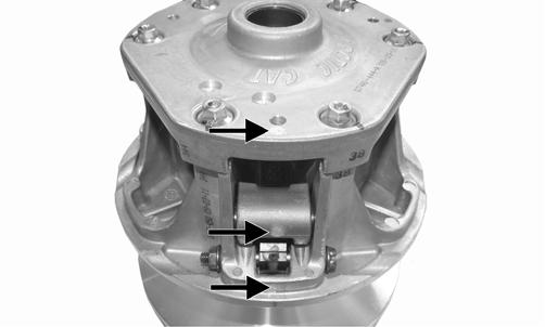
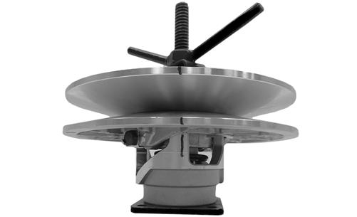
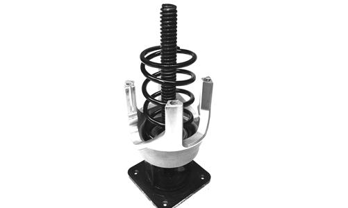
DISASSEMBLING 1. Place the driven clutch on the Driven Clutch Compressor Tool; then install the compressor flange and compress the driven clutch spring. 2. Mark the moveable sheave, stationary sheave, and the torque bracket for assembly purposes.
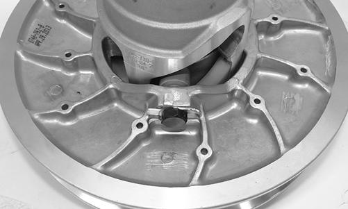
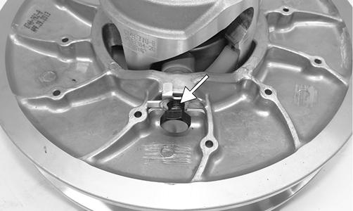
XM139 3. Apply heat to the screws securing the torque bracket to the movable sheave; then remove the screws.
XM140
NOTE: Heat must be used to soften the Loctite using a torch or damage to the screw will occur.
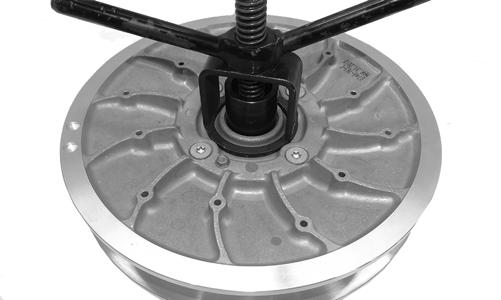
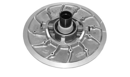
4. Release the compression of the spring by removing the wing nut; then remove the movable sheave. 5. Remove the stationary sheave; then remove the plastic spring seat. Account for the driven spacer.
5. Remove the spring and remaining spring seat.
XM141
PC112
CLEANING AND INSPECTING 1. Using parts-cleaning solvent, wash grease, drive belt dust, and foreign matter off all components. 2. Inspect the rollers for damage, cracks, or wear. 3. Inspect the sheaves for any gouges, cracks, or other damage. Also, inspect threaded areas of sheaves for damaged or stripped threads. 4. Inspect the back-side cams and torque bracket for cracks or damage. The ramp portions of the bracket must be free of gouges and damage. Minor scratches may be repaired using #320 grit wet-or-dry sandpaper. 5. Inspect spring for distortion, crystallization, or breaks. 6. Inspect the cover and movable sheave bearing for wear. If wear is present, replace the bearing using
Movable Sheave Bearing Tool. REPLACING TORQUE BRACKET BEARING/COVER BEARING 1. Remove the snap ring. 2. Using a suitable driving tool, drive the bearing out.
3. Install the new bearing; then secure with a new snap ring. REPLACING ROLLERS 1. Bend the locking tabs down away from the shoulder bolt; then remove the bolt.
CAUTION
Do not use steel wool or a wire brush to clean driven clutch components. A wire brush or steel wool will cause the sheaves to be gouged (thus, the drive belt may not slide properly between sheaves). Decreased performance and possible accelerated drive belt wear will result. ! WARNING
Always wear safety glasses when using the bearing driver.
XM143 2. Place a new roller into position and secure with the shoulder bolt (with a drop of red Loctite #271).
Tighten securely and bend the lock tabs to contact the bolt head.
NOTE: If the flat does not align with the tab, tighten the shoulder bolt until it aligns.
XM144A
ASSEMBLING 1. Place the torque bracket onto the Driven Clutch
Compressor Tool; then install the spring seat (flat side toward the spring) onto the torque bracket and place the spring into position.
PC112
NOTE: Premature wear will result if the spring seat is not installed.
2. Place the stationary sheave spring seat onto the spring (flat side toward the spring); then noting the alignment marks made during disassembling, place the stationary sheave onto the torque bracket. 3. Place the movable sheave onto the stationary sheave. 4. With the clutch in place on the compressor, install the compressor flange spacer and wing nut; then compress the driven clutch spring.
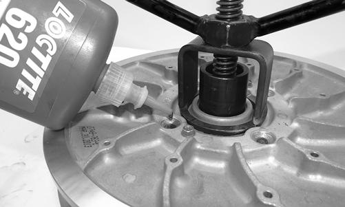
XM139 5. With the driven clutch compressed, apply a small amount of green Loctite #620 to the machined area of the movable sheave so the loctite can drip onto the threads of the torque bracket.
XM142 6. Install new screws securing the movable sheave.
Tighten in a crisscross pattern to 27 ft-lb.
XM140
7. Remove the clutch from the compressor. 8. Install the back-side cams; then secure with the screws and tighten to 24 in.-lb. INSTALLING 1. Set the brake lever lock. 2. Install the alignment washers; then install the driven clutch. Tighten to 20 ft-lb (threads coated with blue
Loctite #243). 3. Check drive clutch/driven clutch alignment; then install the drive belt.
Drive Clutch/Driven Clutch
If premature drive belt wear is experienced or if drive belt turns over, check parallelism/offset. Also, parallelism/offset must be checked whenever either drive clutch or driven clutch is serviced. To check offset, use appropriate Clutch Alignment Bar. To check parallelism, use Parallelism Bar. CHECKING OFFSET 1. With the engine off, open the left-side access panel; then remove the belt guard. Remove the drive belt. 2. Install appropriate Clutch Alignment Bar between the drive clutch sheaves.
3. Allow the bar to rest on the drive clutch shaft and against the outside edge of the driven clutch stationary sheave. NOTE: The alignment bar must extend beyond the front edge of the drive clutch.
4. With the bar against the outside edge of the driven clutch stationary sheave at points A and B, the bar should just clear the inside edge of the stationary sheave of the drive clutch and rest on the stationary shaft at point C. If the bar either will not clear the inside edge or is more than the specified amount, the offset must be corrected.
0747-959
CORRECTING OFFSET 1. To correct offset, the driven clutch must be moved laterally on the input shaft. Remove the cap screw and washers securing the driven clutch. NOTE: If the driven clutch is tight on the shaft, pull the driven clutch off using the Driven Clutch Puller.
2. To move the driven clutch inward on the shaft, remove alignment washers located on driven shaft from the chain case of the clutch. 3. To move the driven clutch outward on the shaft, add alignment washers to the driven shaft on the chain case of the clutch. 4. Arrange washers to obtain correct offset; then install driven clutch, cap screw, and washers. 5. Install the drive belt.
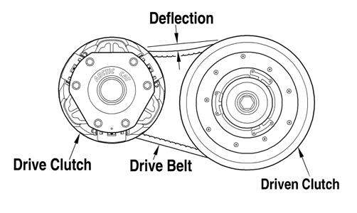
DRIVE BELT DEFLECTION Drive belt length, condition, and deflection are all important for peak performance. To check and adjust drive belt deflection, use the following procedure. NOTE: Make sure the drive belt is sitting at the top of the driven clutch sheaves.
1. Place a straightedge on top of the drive belt. The straightedge should reach from the drive clutch to the top of the driven clutch. 2. Using a stiff ruler centered between the drive clutch and driven clutch, push down on the drive belt just enough to remove all slack. Note the amount of deflection on the ruler at the bottom of the straightedge. The deflection should be at 1 1/4 in.
0743-319
NOTE: Push down on the belt with the ruler only until the bottom of the belt flexes upward; then read the amount of deflection.
3. To correct drive belt deflection, remove the sheave adjuster from the clutch, remove or add shim washers to the adjuster, and install the adjuster. NOTE: Adding shim washers will decrease belt deflection; removing shim washers will increase belt deflection.
Drive Train
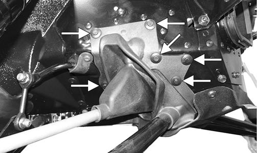
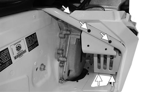
If the chain or sprocket on 7000 models need to be replaced for any reason, only use the correct chain or sprocket in the parts manual. Using a different chain or sprocket will cause damage due to the different tooth profiles. 1. Remove the left- and right-side panels and the hood; then disconnect the oxygen sensor and remove the resonator. Discard exhaust gaskets, cap screws, and nuts but retain the exhaust spring. 2. Remove the torx-head screw securing the belly pan to the right-side foot rest support; then remove the torx-head screws securing the right-side foot rest.
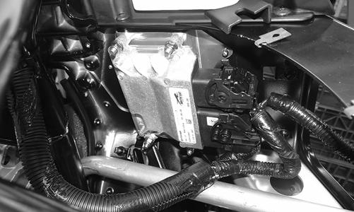
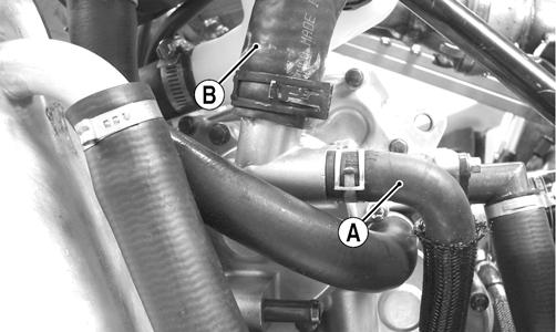
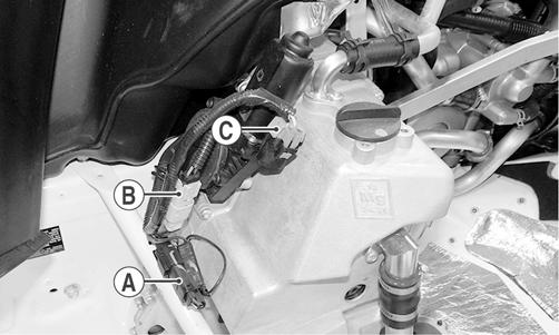
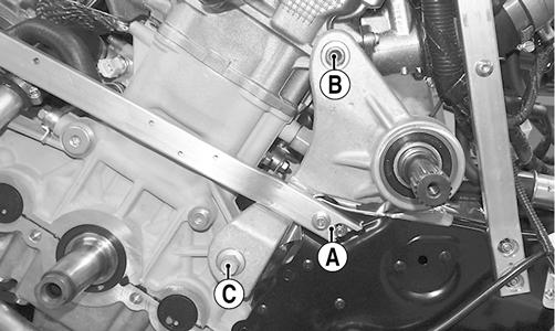
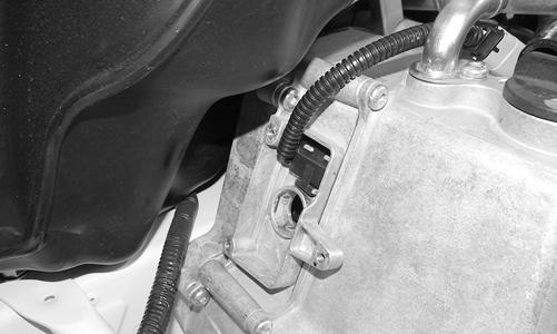
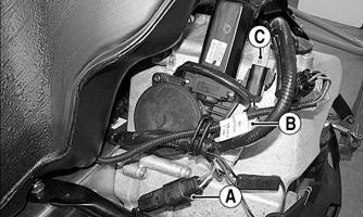
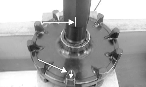
SNO-960A 3. Disconnect the speed sensor connector (A), gear position sensor connector (B), and reverse actuator connector (C).
SNO-961A 4. On 5000 and 9000 models, remove the clamp securing the oil separator line; then remove the line from the oil tank elbow fitting.
SNO-963A
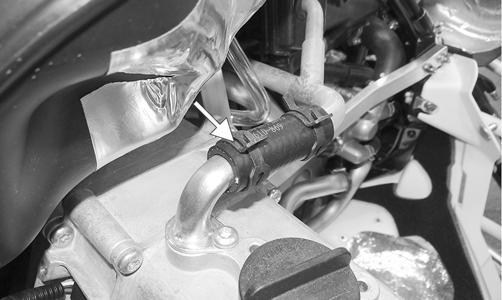
NOTE: On 7000 models, the oil separator line is vertical but still needs to be removed from the oil tank fitting. 5. Remove the reverse shift actuator; then remove the actuator extension from the chain case. 6. To drain the chain lube, place a drain pan under the chain case; then loosen the eleven screws securing the chain case cover/oil tank assembly to the chain case housing starting at the bottom. NOTE: Do not remove all eleven screws completely until the chain lube has been completely removed. This will help keep debris/oil out of the screw holes. 7. Swing the chain case out of the way. Account for a thrust washer on the countershaft.
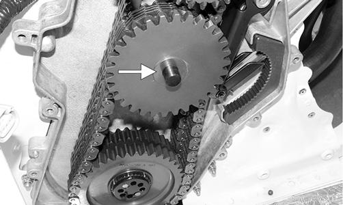
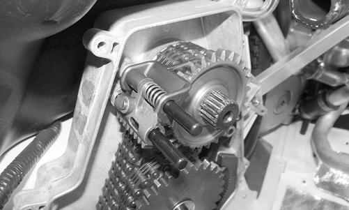
SNO-964A 8. Remove the reverse gear, reverse fork, reverse shift rack, and the reverse shift shaft as an assembly.
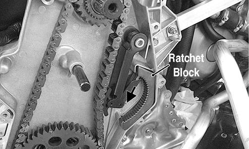
SNO-965A 10. On 5000 and 9000 models, release tension on the chain tensioner; then remove the ratchet block. The tensioner does not need to be removed.
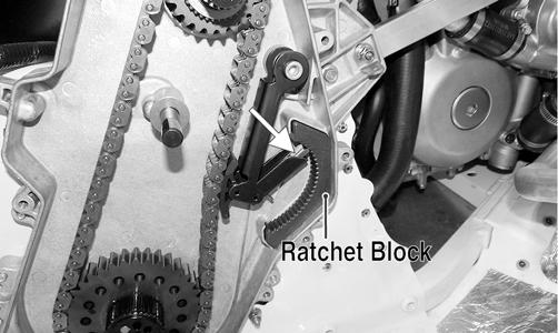
SNO-966A
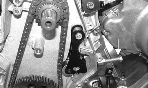
NOTE: On 7000 models, loosen the tensioning cap screw enough so the tension is removed from the chain.
YM-053A
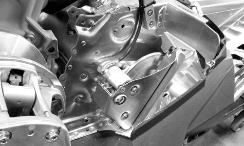
11. Remove the sprockets and chain. NOTE: If the driven shaft and driveshaft are going to serviced, proceed to Cleaning and Inspecting Chain Case. If bearings and chain or case assembly are to be replaced, remove the driven clutch; then proceed to step 12. 12. Remove the left-side chassis support. 13. On 5000 and 9000 models, remove the left and right rear engine mount bolts (A); then remove the Allenhead screw (B) and cap screw (C) securing the left rear engine mount to the engine.
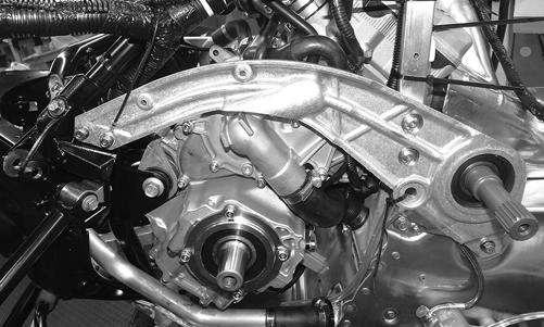
XM091A 14. On 7000 models, once the cap screws and nuts securing the left-side chassis support are removed, carefully remove the support and drive shaft.
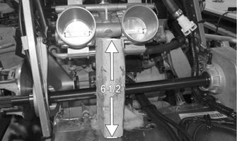
YM-054 15. On 5000 and 9000 models, lift and support the engine at the rear to allow the engine mount to clear chassis. NOTE: A support can be cut from a wood block 6 1/ 2” long and placed under the throttle bodies for support.
PC169A PC163A
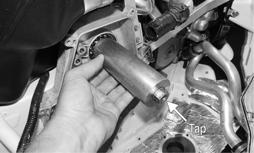
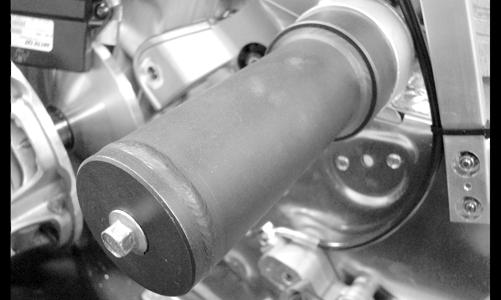
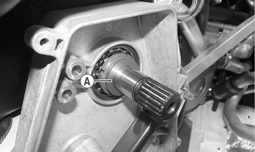
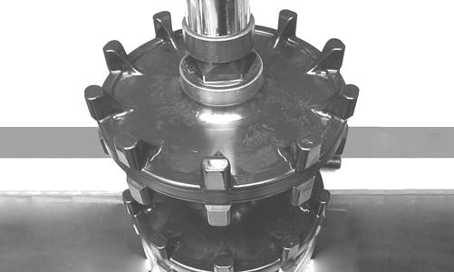
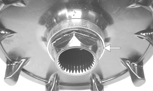
16. Bend the locking tab out of the ring nut; then with the Socket loosen (but do not remove) the ring nut.
Lightly tap the socket to disengage the adapter sleeve or the shaft will not slide.
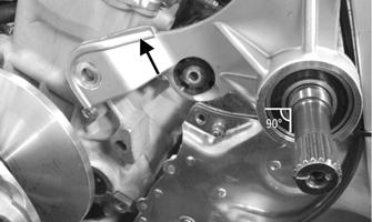
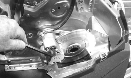
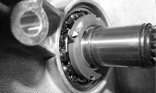
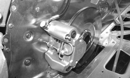
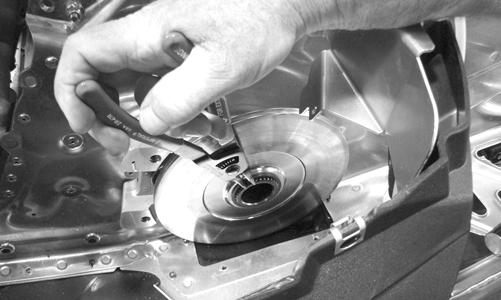
SNO-970A 17. Remove the inner retaining ring; then from the left side, carefully remove the driven shaft assembly keeping the bearing 90° to the shaft. 18. Remove the skid frame assembly. 19. Remove the brake cover and the left-side footrest. NOTE: DO NOT split the brake caliper unless necessary service work is required. 20. Remove the cap screws securing the inner caliper to the tunnel; then remove the inner caliper.
YM-077A 21. Pull the driveshaft out to the left; then drop out of tunnel right side first. NOTE: If the calliper does not remove from the driveshaft easily, proceed to step 22.
22. Remove the brake pads; then remove the outer brake caliper. Account for a rubber seal. NOTE: Place an absorbent towel under the caliper to absorb slight amount of brake fluid. Do not compress the brake lever.
PC172 23. Remove the retaining ring securing the brake disc to the driveshaft and remove the brake disc. NOTE: It may be necessary to use Brake Caliper Bearing Puller (p/n 0744-067) to remove the caliper/ bearing assembly. 24. If the chain case needs to be removed, remove all self-tapping screws and machine screws with lock nuts. CLEANING AND INSPECTING CHAIN CASE 1. Inspect sprockets and chain(s) for excessive wear or stretching. 2. Inspect bearings and gears for roughness or chipping. NOTE: If bearing replacement is necessary, the chain case must be removed from the tunnel and an appropriate press utilized to remove and install bearings. 3. Inspect reverse shift rack and fork for excessive wear, discoloration, or other damage. 4. Clean all interior chain case surfaces and components in cleaning solvent and dry using compressed air.
! WARNING
Always wear safety glasses when using compressed air.
5. Inspect chain snubbers for excessive wear. ASSEMBLING/INSTALLING CHAIN CASE/DRIVEN SHAFT/DRIVESHAFT/ TRACK
If the driveshaft and driven shaft were not removed, proceed to step 16. 1. Install chain case assembly onto chassis and secure with six self-tapping screws and four machine screws with lock nuts. Tighten the self-tapping screws to 12 ft-lb.
NOTE: If an existing chain case is being reinstalled, tighten the self-tapping screws to 105 in.-lb. 2. Place the driveshaft/drive sprocket assembly into the tunnel brake-end first; then into the chain case driveshaft bearing. 3. Install the inner brake caliper assembly and secure with three cap screws and the retaining ring. Tighten the cap screws securely.
YM-077A
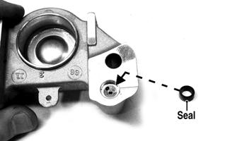
NOTE: If the brake caliper was split, proceed to step 4. If not, proceed to step 6. 4. Install the brake disc and secure with the retaining ring. 5. Making sure the seal is correctly installed in the outer brake caliper, install on the inner caliper and secure with two cap screws. Tighten to 25 ft-lb.
PC173A
6. Install the skid frame. 7. Install the brake cover and left-side footrest. Tighten the cover cap screws to 8 ft-lb. NOTE: Bleed the brake system if the brake caliper was split in this section. 8. Install the driven shaft from the left side making sure the bearing remains at 90° to the shaft.
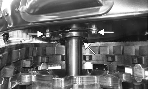
PC177 9. On 5000 and 9000 models, install the screws (threads coated with blue Loctite #243) securing the
PTO-side engine mount to the engine. Tighten the upper and lower screws to 100 ft-lb.
XM037 10. Install the right rear engine mount bolt and secure with a new lock nut. Tighten securely. 11. Install the side chassis support and the left rear engine mount bolt with a new lock nut. Tighten securely. NOTE: On 7000 models, install the driven shaft from the left side; then secure the support to the chassis using the existing cap screws and nuts. Tighten to 20 ft-lb.
YM-054 12. Install the drive clutch and tighten the clutch cap screw to 51 ft-lb; then install the driven clutch and drive belt. Tighten to 20 ft-lb (threads coated with blue Loctite #243). 13. Add a few drops of Chain Lube to the threads of the adapter sleeve; then install the ring nut and tighten to 50 ft-lb using the socket.
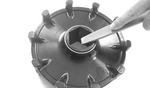
NOTE: The tabs on Socket (p/n 0644-516) must be 0.175-in. long so the tool only catches the ring nut. Grinding of the tabs on the tool may be required. 14. Bend locking tab into one of the slots in the ring nut.
SNO-969B NOTE: If no tabs align with the slots, tighten ring nut until one aligns; then bend tab to lock ring nut. 15. Using a caliper, measure from the retaining ring groove to the adapter sleeve. Install the existing flat washers (1.00 x 1.43 x .030 and/or 1.00 x 1.43 x .075) between the groove and the adapter sleeve.
Install the existing black retaining ring (A).
SNO-971A
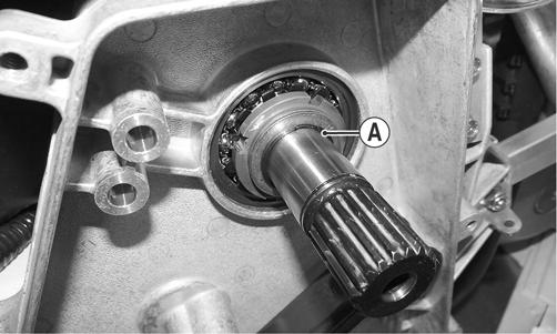
NOTE: The correct combination of washers need to stack up to take up the space in between the adapter sleeve and the retaining ring, yet small enough for the retaining ring to secure properly and the washers to rotate freely. 16. Install the existing thrust washer (A) next to the retaining ring.
PC085A
NOTE: On 7000 models, turn the chain tension adjustment bolt clockwise until it is finger tight; then loosen it 1 1/2 turns. While holding the bolt with a wrench, tighten the jam nut to 18 ft-lb.
YM-053
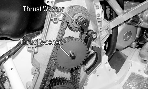
18. Install the reverse sprockets and chain. 19. Secure the driveshaft reverse sprocket to the driveshaft with a retaining ring; then install a existing thrust washer on the outside of the upper reverse sprocket and reverse idler shaft.
SNO-965A SNO-973A 20. Install the reverse gear, fork, shift shaft, and shift rack assembly into the chain case.
SNO-979 21. Install the chain case cover/oil tank assembly and secure with the screws. Tighten in a crisscross pattern to 105 in.-lb. 22. Fill the chain case with 12 oz of Arctic Cat Chain
Lube. NOTE: Make sure the gear position sensor wires are routed up and over the top side of the actuator so they are not pinched when installing the reverse shift actuator.
SNO-982 23. Install the actuator extender; then install the reverse actuator and with a drop of blue Loctite #243 on each screw, secure the actuator to the chain case cover. 24. Using new O-rings, install the oil supply, oil return, and oil separator return fittings onto the oil tank and tighten securely. Fill the oil tank with the recommended amount of engine oil.
25. Connect the speed sensor connector (A), the gear indicator switch connector (B), and reverse actuator connector (C).
PC067A
NOTE: If the driven shaft was removed, proceed with step 26. 26. Install the air silencer; then connect the inlet air temperature sensor connector. 27. Install the right-side footrest support and secure to the belly pan using the torx-head screw; then install the right-side footrest. 28. Install the seat.
29. Start the engine and with the snowmobile on a jack stand; then shift the snowmobile into and out of reverse three times.
CAUTION
At this point before starting the engine, cycle the key ON then OFF to ensure the forward gear position is selected. Failure start the engine with the gears in forward could result in damage to the gears.
Drive Sprockets
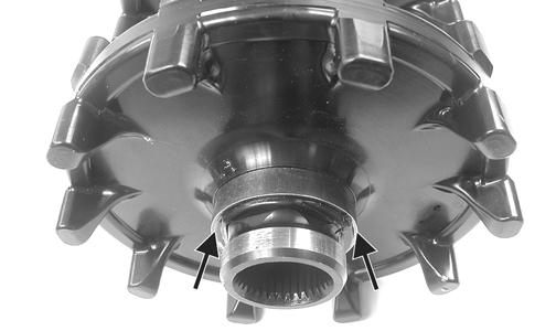
REMOVING NOTE: The drive sprockets must be removed from the brake side.
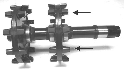
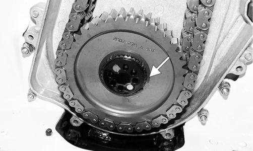
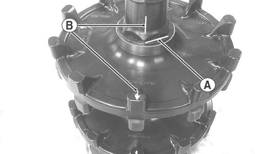
ZJ216A 1. For installing purposes, scribe a line on the driveshaft (A) next to the drive sprocket for proper alignment; then scribe a line on the driveshaft directly in line with the timing arrows (B) on the drive sprockets for proper sprocket timing.
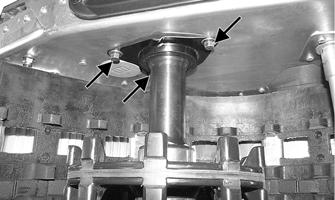
MS357A 2. Using a suitable press positioned against the tensioncollar of the drive sprocket (located on the gear case) and of the driveshaft, press the drive sprockets off the driveshaft.
ZJ217
CAUTION
Always press against the tension-collar of the drive sprockets or damage to the components will occur.
ZJ218A
CLEANING AND INSPECTING 1. Thoroughly wash all metallic components in partscleaning solvent. Dry using compressed air. 2. Wash all non-metallic components with soap and water. 3. Inspect the driveshaft for damaged splines or stripped threads. 4. Inspect the seals for any breaks or damage. 5. Inspect the track for cuts, gouges, or wear. 6. Inspect the brake disc for wear or cracks.
7. Inspect the track drive sprockets for wear or damage. INSTALLING NOTE: The drive sprockets must be installed on the brake side.
ZJ216A
NOTE: Prior to installing the sprockets onto the driveshaft, lightly chamfer the inside edge of the sprocket to avoid binding.
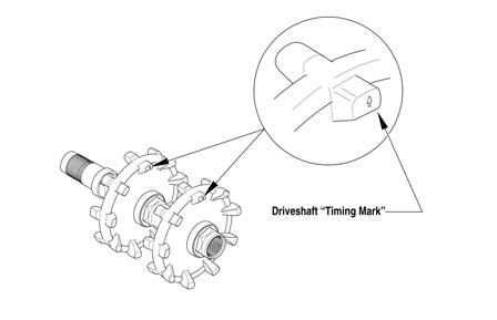
MS362 1. Properly align the scribed line on the driveshaft (from removing) with the timing arrow on the drive sprocket; then slide the sprocket onto the driveshaft as far as it will go.
MS360A 2. Using a suitable press and fixture, press the driveshaft into the sprocket until it aligns with the line scribed in removing.

MS361A 3. Slide the remaining sprocket onto the driveshaft making sure the timing arrow/lines (from removing) are aligned; then using the press/fixture, press the sprocket to the remaining alignment line.
CAUTION
Always press against the tension-collar of the drive sprockets or damage to the components will occur.
MS359A
NOTE: The drive sprockets must be installed on the brake disc end of the driveshaft.
MS313C
NOTE: When pressing new sprockets on the driveshaft, align the sprocket alignment marks or the sprockets won’t be timed correctly.
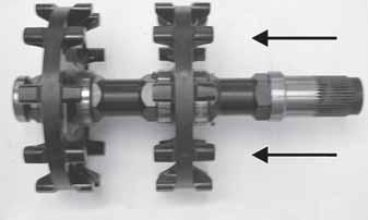
740-043A 4. Using a calipers, measure distances between the sprockets and from the sprockets to each end of the driveshaft for proper location (see appropriate illustration).
ZR 5000
XF 7000 LXR/Sno Pro/LTD ZR 7000 LXR/Sno Pro/Sno Pro LTD
XF 9000 LXR/Sno Pro/Sno Pro LTD ZR 9000 XF 7000 CC/CT
0747-960
0747-770
0747-963
0747-961 0747-964
Track Tension
CHECKING
! WARNING
DO NOT attempt to check or adjust track tension with engine running. Turn ignition key to the OFF position. Personal injury could result from contact with a rotating track.
1. Remove excess ice and snow buildup from the track, track drive sprockets, and the inside of the skid frame. 2. Elevate the snowmobile on a shielded safety stand high enough to use a spring scale. 3. At mid-point of the track (on the bottom side), hook a spring scale around a track clip; then pull down on the scale to the12-15 lb pressure. Measure the deflection (distance) between the bottom of the wear strip and the inside surface of the track clip. Measurement should be 2 in. NOTE: Measurement is from the bottom of the wear strip at the point of the shock pad on the slide rail. ADJUSTING NOTE: To ensure proper track tension adjustment, perform all adjustments on both sides of the snowmobile.
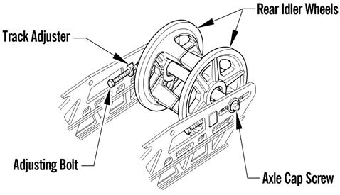
1. Loosen the idler wheel axle cap screws.
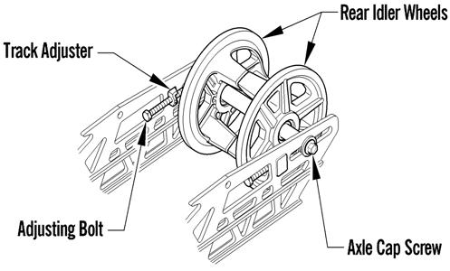
0745-811 2. If the deflection (distance between the bottom of the wear strip and the inside surface of the track clip) exceeds specifications, tighten the adjusting bolts to take up excessive slack in the track. 3. If the distance between the bottom of the wear strip and the inside surface of the track clip is less than specified, loosen the adjusting bolts to increase the slack in the track.
CAUTION
Always maintain track tension within recommended specification. 4. Check track alignment (see Track Alignment subsection in this section). 5. After proper track tension is obtained, tighten the idler wheel axle cap screws to 34 ft-lb. NOTE: Since track tension and track alignment are interrelated, always check both even if only one adjustment seems necessary.
! WARNING
Always make sure the adjusting bolts are snug against the axle and the idler wheel cap screws and the axle nut on the RR models are tightened to specifications. Failure to do so could cause the track to become extremely loose and, under some operating conditions, allow the idler wheels to climb over the track lugs forcing the track against the tunnel causing the track to “lock.” If a track “locks” during operation, severe personal injury could result.
Track Alignment
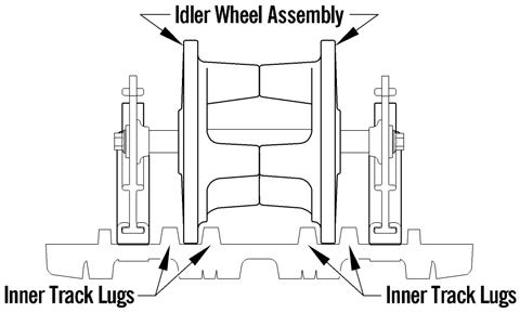
NOTE: Proper track alignment is when the rear idler wheels are equidistant from the inner drive lugs on the inside surface of the track.
CHECKING/ADJUSTING ! WARNING
Make sure the ignition key is in the OFF position and the track is not rotating before checking or adjusting track alignment. Personal injury could result if contact is made with a rotating track. 1. Remove excess ice and snow buildup from the track, track drive sprockets, and the inside of the skid frame. 2. Position the tips of the skis against a wall; then using a shielded safety stand, raise the rear of the snowmobile off the floor making sure the track is free to rotate.
! WARNING
The tips of the skis must be positioned against a wall or similar object for safety. Keep hands, feet, and clothing away from moving components. ! WARNING
DO NOT stand behind the snowmobile or near the rotating track. NEVER run the track at high speed when the track is suspended.
3. Start the engine and accelerate slightly. Use only enough throttle to turn the track several revolutions.
SHUT ENGINE OFF. NOTE: Allow the track to coast to a stop. DO NOT apply the brake because it could produce an inaccurate alignment condition. 4. When the track stops rotating, check the relationship of the rear idler wheels and the inner track drive lugs.
If the rear idler wheels are centered between the inner track drive lugs, no adjustment is necessary. If not, proceed to step 5.
0745-809 5. On the side of the track which has the inner track drive lugs closer to the rear idler wheel, loosen the idler wheel axle cap screw; then rotate the adjusting bolt clockwise 1 to 1 1/2 turns.
0745-811 6. Check the track alignment and make the necessary adjustments until proper alignment is obtained. NOTE: Make sure correct track tension is maintained after adjusting track alignment (see Track Tension sub-section in this section).
7. After proper track tension and alignment are obtained, tighten the idler wheel axle cap screw to 34 ft-lb; then tighten the adjusting bolt to 84 in.-lb. ! WARNING
Always make sure the adjusting bolts are snug against the axle and the idler wheel cap screws and the axle nut on the RR models are tightened to specifications. Failure to do so could cause the track to become extremely loose and, under some operating conditions, allow the idler wheels to climb over the track lugs forcing the track against the tunnel causing the track to “lock.” If a track “locks” during operation, severe personal injury could result. NOTE: Field test the track under actual conditions and after the field test, check track alignment and track tension; adjust as necessary.
Brake System (Hydraulic)
CHECKING BRAKE LEVER TRAVEL 1. Compress the brake lever fully. NOTE: Do not pump the brake lever as it will produce an inaccurate reading. 2. Measure the distance between the brake lever and the handlebar. The distance must be greater than 1in.
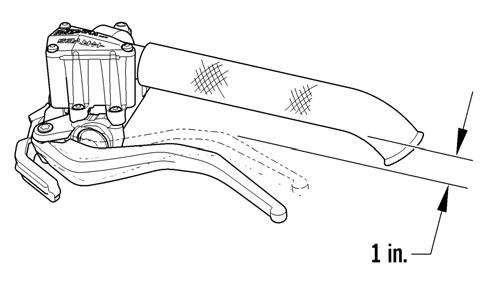
0745-816 3. If the distance is less than specified, check the brake fluid level (see Checking and Adding Brake Fluid in this sub-section), inspect for leakage, and check the brake pads (see Checking and Replacing Brake Pads in this sub-section).
CHECKING AND ADDING BRAKE FLUID 1. With brake fluid reservoir in a level position and the cover removed, check the fluid level. The brake fluid level must be at the high mark in the reservoir.
! WARNING
Do not operate the snowmobile if the distance between the compressed brake lever and handlebar is less than 1 in. Brake loss may occur. Brake loss can result in severe personal injury.
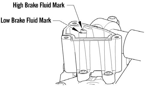
0745-817 2. If the brake fluid level is low, add Arctic Cat approved brake fluid until the fluid is at the recommended level. Install and secure the reservoir cover.
DO NOT allow moisture to contaminate the brake system.
CHANGING BRAKE FLUID The brake fluid must be changed on a regular basis and/ or whenever the brake fluid has been overheated or contaminated. The brake fluid should be changed every 1000 miles or at the end of the snowmobiling season, whichever occurs first. Arctic Cat recommends the removal and disassembly of the brake caliper assembly when changing the brake fluid (see Brake Caliper/Brake Disc/Driveshaft Bearing in this sub-section).
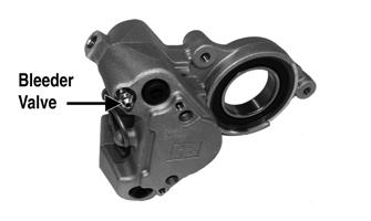
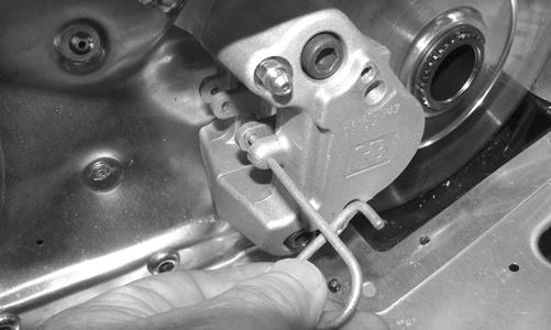
1. Slide a piece of flexible tubing over the ball of the bleeder valve and direct the other end into a container. CAUTION
Brake fluid is highly corrosive. Do not spill brake fluid on any surface of the snowmobile. ! WARNING
Do not overfill the brake fluid reservoir. Overfilling the reservoir may cause the brake system to hydraulically lock. Use only approved brake fluid. Never substitute or mix different types or grades of brake fluid. Brake loss may occur. Brake loss can result in severe injury or even death.
CAUTION
Brake fluid is highly corrosive. Do not spill brake fluid on any surface of the snowmobile. ! WARNING
Use only Arctic Cat approved brake fluid. Any substitute may result in a loss of brakes.
PC223A 2. Slowly compress the brake lever and hold. Open the bleeder valve to release the fluid; then compress the brake lever repeatedly until all brake fluid is expelled. Close the bleeder valve. 3. Add new approved brake fluid to the reservoir; then compress the brake lever and hold. Open the bleeder valve. Repeat the compression until brake fluid flows free of air bubbles and appears clean. NOTE: It may be necessary to refill the reservoir a number of times to eliminate all air bubbles in the system. 4. When the brake fluid is free of all air and the brake lever feels firm when compressed, fill the reservoir; then install and secure the cover. Remove the tube from the bleeder valve. 5. Bleed the brake system (see Bleeding Brake System in this sub-section). BLEEDING BRAKE SYSTEM If the brake lever feels spongy when applied, the brake system may need to be bled. 1. With the handlebar in the highest position, remove the reservoir cover and fill the reservoir with approved brake fluid.
2. Slide a piece of flexible tubing over the ball of the bleeder valve and direct the other end into a container. CAUTION
Brake fluid is highly corrosive. Do not spill brake fluid on any surface of the snowmobile. ! WARNING
Use only approved brake fluid. Any substitute may result in a loss of brakes. ! WARNING
Do not use brake fluid from a container opened for a long period of time. Unsealed brake fluid containers will absorb moisture and can contaminate the fluid inside.
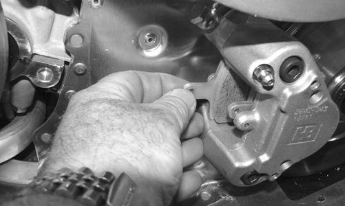
PC223A 3. Slowly compress the brake lever and hold. Open the bleeder valve to release the fluid and air. When the fluid stops flowing, close the bleeder valve; then release the brake lever. 4. Repeat step 3 until the brake fluid flows free of air bubbles. NOTE: It may be necessary to refill the reservoir during the bleeding process. 5. When the brake fluid is free of all air and the brake lever feels firm when compressed, fill the reservoir; then install and secure the cover. Remove the tube from the bleeder valve. CHECKING AND REPLACING BRAKE PADS 1. Remove the brake shield; then remove the retaining pin securing the brake pads.
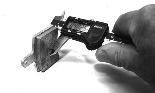
PC195 2. Remove one brake pad and measure the thickness.
PC196
PC199
NOTE: Brake pad thickness must be greater than 0.20 in. If brake pad thickness is less than specified, replacement of both pads is necessary. Always replace with new pads and always replace as a set. 3. Position the new brake pad into the caliper. 4. Repeat for the other pad; then secure the pads with the retaining pin.
PC194
NOTE: When new brake pads are installed, a “burnishing” process is required. Drive the snowmobile slowly and compress the brake lever several times until the pads just start to warm up; then allow them to cool down. This procedure stabilizes the pad material and extends the life of the pads. BRAKE CALIPER/BRAKE DISC/ DRIVESHAFT BEARING
Removing/Disassembling 1. Remove both access panels; then remove the drive belt (see Drive Belt in this section) and driven clutch. 2. Remove the screws securing the brake shield and footrest to the chassis; then remove the shield and rest.
PC170 3. Slide a piece of flexible tubing over the ball of the bleeder valve and direct the other end into a container.
PC223A
CAUTION
Brake fluid is highly corrosive. Do not spill brake fluid on any surface of the snowmobile. 4. Open the bleeder valve and compress the brake lever several times to drain the reservoir of fluid. 5. Remove the brake hose from the caliper. Use an absorbent towel to collect any remaining brake fluid. 6. Remove the retaining pin securing the brake pads; then remove both pads.
PC195
NOTE: If servicing the brake disc only, remove the cap screws securing the caliper housings together; then remove the outside housing. Account for the seal.
PC172
CAUTION
If the caliper housings are to be separated, take care not to allow any contaminants into the fluid passages of the calipers. NOTE: To aid in removing the inner caliper housing, completely loosen track tension. 7. Remove the retaining ring from the driveshaft and remove the brake disc; then remove the cap screws securing the inner caliper/driveshaft bearing housing to the chassis.
PC174
PC148A 8. If the bearing will be replaced, remove the retaining ring; then using a suitable press, remove the bearing from the housing.
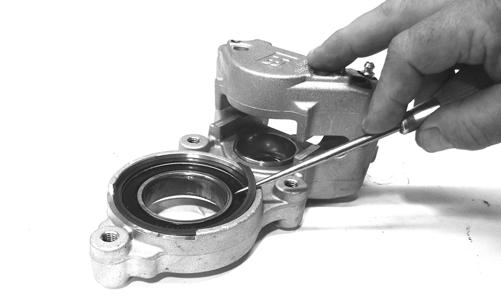
PC200
NOTE: Never reuse bearings that have been removed. Always use new bearings.
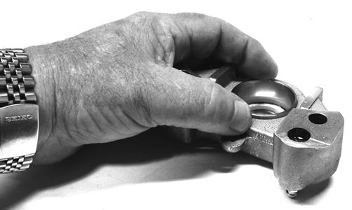
NOTE: If the caliper housings were separated, they must be secured together with the seal installed between the inner and outer housings. 9. Position a piece of wood between the pistons. Using low-pressure compressed air, blow into the caliper brake hose fitting to loosen the brake pistons. ! WARNING
Always wear safety glasses when using compressed air.

PC221A 10. Remove the two screws securing the caliper halves.
Discard the seal.

PC219A
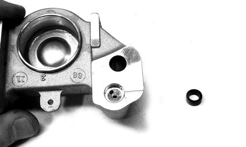
PC173 11. Remove the pistons (A) and O-rings (B); then discard the O-rings.
PC220A
Cleaning and Inspecting 1. Inspect the brake pistons for gouges, cracks, pitting, scuffing, or corrosion. If any of these conditions exist, replace the piston. NOTE: The inner and outer caliper housings are not serviceable components. If either or both are defective or damaged, the complete caliper assembly must be replaced. 2. Clean the piston outer surface by using a soft Scotch-
Brite pad and clean brake fluid as a cleaner.
3. Inspect the piston bore of the inner and outer brake calipers for gouges, cracks, pitting, scuffing, or corrosion. If any of these conditions exist, replace the caliper. 4. Clean the caliper inner wall surface using a soft lintfree cloth and clean brake fluid.

5. Inspect the condition of the brake pads. Replace if damaged or worn. The brake pad thickness must be greater than 0.20 in. If the brake pad thickness is less than specified, replacement of both pads is necessary. 6. Inspect the brake hose for cracks and deterioration and check the condition of the threaded connectors. Assembling/Installing 1. Apply approved brake fluid to new O-rings; then install the O-rings into the groove of each caliper half.
2. In each caliper half, apply approved brake fluid to the brake piston; then while twisting, install the piston with the dished side facing out.
CAUTION
Do not use any sharp cleaning tool on the piston surface or in the O-ring groove as it may cause damage.
CAUTION
Care must be taken not to allow any contaminants into the fluid passages of the calipers or brake system malfunction may occur. CAUTION
Never reuse piston O-rings. Always install new Orings when installing pistons in the brake caliper.
PC201
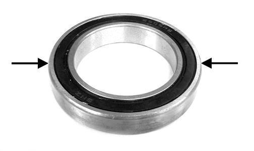
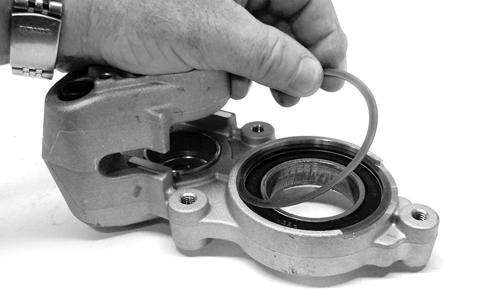
NOTE: To aid in installing the piston, make sure the piston O-ring is properly seated in the groove of the caliper housing. 3. Using a suitable press, install a new inner bearing into the caliper housing until it is properly seated.
CAUTION
When installing a bearing, always press on the outer race of the bearing.
ZJ239A 4. Install the snap ring securing the bearing in the caliper housing.
PC204 5. Place the inner caliper housing/driveshaft bearing housing onto the driveshaft and secure with the cap screws coated with blue Loctite #243. Tighten to 25 ft-lb. 6. Apply Anti-Seize Thread Compound to the splines of the brake disc; then install on the driveshaft and secure with the retaining ring. 7. Install a new seal in the outer caliper fluid passage; them install the outer caliper and secure with the cap screws. Tighten to 25 ft-lb.
PC173A 8. Install new brake pads in the caliper and secure with the retainer pin.
PC195
9. Bleed the brake system. 10. Install the brake shield and footrest; then install the drive belt and driven clutch. Tighten the driven clutch cap screw to 20 ft-lb. 11. Adjust the track tension and track alignment. 12. Close and secure both side panels.
Brake Lever/Master Cylinder Assembly
REMOVING 1. Slide a piece of flexible tubing over the ball of the bleeder valve and direct the other end into a container.
PC223A 2. Remove the two screws securing the reservoir cover and remove the reservoir cover; then open the bleeder valve. Allow the brake fluid to drain completely. 3. Place an absorbent towel around the connection to absorb brake fluid. Remove the banjo-fitting bolt (A) securing the brake fluid hose (B) to the master cylinder. Discard the two crush washers.
CAUTION
Brake fluid is highly corrosive. Do not spill brake fluid on any surface of the snowmobile.
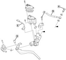
745-759A 4. Remove the pin (D) securing the brake lever to the master cylinder. 5. Using a small screwdriver, compress the tabs of the brakelight switch (E) to release it from the master cylinder. 6. Remove the two torx-head screws (F) and clamp securing the brake reservoir to the handlebar; then place a towel over the reservoir and remove the assembly from the handlebar.
INSPECTING 1. Inspect the snap ring and pin securing the brake lever for wear or damage; then inspect the brake lever for cracks or damage. 2. Inspect the master cylinder reservoir and cover for cracks and leakage. NOTE: The master cylinder is a non-serviceable component. If any wear or damage is detected, the master cylinder must be replaced. 3. Inspect the brake fluid hose for cracks, deterioration, and the condition of the fittings (threaded and compression). INSTALLING 1. Position the brake assembly on the handlebar. Secure with two torx-head screws (F) and clamp; tighten securely. 2. Install the brake fluid hose (B) to the master cylinder with the banjo-fitting bolt (A) and two new crush washers. Tighten securely.
3. Install the brakelight switch (E) to the master cylinder. 4. Install the brake lever; then secure with pin (D). 5. Place the reservoir cover onto the reservoir; then secure with the two screws. 6. Bleed the brake system.
CAUTION
Always use new crush washers when installing the brake fluid hose.
Troubleshooting Track
Problem: Track Edge Frayed — Drive Lugs Worn Condition Remedy 1. Track alignment adjusted incorrectly 1.Align — replace track Problem: Track Worn Adjacent to Outer Drive Lugs Condition Remedy 1. Track tension adjusted incorrectly 1.Adjust track tension 2. Rear idler wheels dirty — damaged 2.Clean — replace idler wheels Problem: Track Ratchets — Slaps Tunnel Condition Remedy 1. Track tension adjusted incorrectly (too loose) 1.Adjust track tension (tighten) 2. Drive sprockets misaligned — damaged 2.Align — replace sprockets Problem: Wear-Strip Wear Excessive Condition Remedy 1. Slide rail bent — broken — damaged 1.Repair — replace slide rail 2. Track alignment adjusted incorrectly 2.Adjust track alignment
Troubleshooting Hydraulic Brake System
Problem: Caliper Leaks Condition
1. Caliper O-ring deteriorated — severed 2. Piston — O-ring damaged Problem: Lever Spongy — Bottoms Out Condition
1. Brake system air bubbles present 2. Master cylinder damaged — faulty Problem: Oscillation Feedback in Lever Condition Remedy
1.Replace O-ring 2.Repair piston — replace piston — O-ring
Remedy
1.Bleed brake system 2.Replace master cylinder
Remedy
1. Brake pad residue present on brake disc 2. Caliper loose 1.Replace pads — clean disc 2.Tighten mounting bolts
Problem: Loss of Brake Condition
1. Brake fluid overheated — contaminated 2. Master cylinder damaged — faulty 3. Caliper — brake hose leaking
4. Brake lever linkage damaged Remedy
1.Replace fluid 2.Replace master cylinder 3.Replace caliper O-ring — repair piston —replace piston —
O-ring — brake hose 4.Repair — replace lever — mounting bolt
Problem: Brakes Drag Condition Remedy
1. Master cylinder damaged — faulty 1.Replace master cylinder 2. Brake pads worn — tapered 2.Replace pads Problem: Snowmobile Won’t Stop — Have to Pull Too Hard on Lever Condition Remedy 1. Pads/brake disc glazed 1.Replace pads — clean disc 2. Brake lever binding 2.Loosen pivot bolt — replace master cylinder 3. Caliper pistons binding 3.Service caliper assembly
Troubleshooting Drive Clutch/Driven Clutch
Problem: Midrange Shift-Up (Too Quickly - Lowers RPM) Condition Remedy
1. Drive clutch spring weak 2. Driven clutch spring weak 3. Driven clutch spring preload tension inadequate 4. Center-to-center distance too close 5. Driven clutch bearing worn — damaged Problem: Midrange Shift-Up (Too Slowly - Raises RPM) Condition
1. Drive clutch components dirty 2. Driven clutch components dirty 3. Driven clutch spring preload tension excessive 4. Driven clutch bearing worn — dirty 1.Replace drive clutch spring 2.Replace driven clutch spring 3.Replace driven clutch spring 4.Adjust center-to-center distance 5.Replace bearing — movable sheave
Remedy
1.Clean drive clutch components 2.Clean driven clutch components 3.Replace driven clutch spring 4.Clean — replace bearing — movable sheave
Problem: Excessive Belt Deposits Condition Remedy
1. Offset/parallelism incorrect 1.Adjust offset/parallelism 2. Drive clutch/driven clutch sheaves rough — damaged 2.Repair — replace — clean drive clutch/driven clutch — dirty 3. Driven clutch movable sheave travel impaired 3.Service driven clutch 4. Driven clutch bearing worn — dirty 4.Clean — replace bearing — movable sheave Problem: Excessive Belt Drag—Impaired Drive Clutch Disengagement Condition Remedy 1. Drive clutch components dirty — damaged 1.Clean — replace drive clutch components 2. Drive belt does not meet measurement specifications 2.Replace drive belt Problem: Engine RPM Suddenly Increases—Drive Clutch Vibrates Condition Remedy 1. Cam arm pin bent — damaged 1.Replace pin 2. Cam arm damaged — broken 2.Replace cam arm 3. Drive clutch out of balance 3.Align — replace components — drive clutch — drive belt Problem: Driven Clutch Vibrates Condition Remedy
1. Driven clutch out of balance 1.Service — replace driven clutch Problem: Drive Clutch Engagement (Before Specified RPM) Condition Remedy 1. Drive clutch spring weak — bent 1.Replace spring 2. Cam arms incorrect — worn 2.Replace cam arms Problem: Drive Clutch Engagement (After Specified RPM) Condition Remedy 1. Drive clutch spring incorrect 1.Replace spring 2. Spider buttons worn 2.Replace clutch Problem: Drive Clutch Sticks Condition Remedy 1. Drive clutch components dirty 1.Clean drive clutch components 2. Movable sheave bent — binding 2.Clean — replace movable sheave 3. Spider buttons worn 3.Replace clutch Problem: Drive Clutch Jerks—Shifts Erratically Condition Remedy 1. Drive clutch dirty 1.Clean — drive clutch components 2. Rollers worn 2.Replace clutch 3. Cam arms rough 3.Polish — replace cam arms 4. Spider buttons worn 4.Replace clutch 5. Sheaves dirty 5.Clean sheaves