32 minute read
Fuel Systems

This section has been organized for servicing the fuel systems; however, some components may vary from model to model. The technician should use discretion and sound judgment when removing/disassembling and assembling/installing components. Whenever any maintenance or inspection is made on the fuel system where fuel leakage may occur, there should be no welding, smoking, or open flames in the area.
WARNING
Since the fuel supply hose may be under pressure, remove it slowly to release the pressure. Place an absorbent towel around the connection to absorb gasoline; then remove the hose slowly to release the pressure. Always wear safety glasses when removing the fuel hoses.
NOTE: Whenever a part is worn excessively, cracked, or damaged in any way, replacement is necessary. SPECIAL TOOLS A number of special tools must be available to the technician when servicing the fuel systems.
Individual Components
Description p/n
3. A fuel pump coil located on the stator operates the low voltage, high output fuel pump. At cranking speed, the high output fuel pump provides enough fuel to charge the fuel rail. 4. An injector coil located on the stator provides the injectors with DC voltage for operation through the ECM. FLOODED ENGINE If the engine should become flooded, set the brake lever lock, compress the throttle lever to the full-open position, and crank the engine over until it starts and clears itself. Release the brake lever lock. FUEL SYSTEM The fuel is first drawn into the electric fuel pump through multiple pick-up valves and hoses. The fuel is then routed through a high-pressure fuel hose to the fuel rail. The fuel pressure is maintained in the fuel rail by the fuel regulator. With the fuel pressure maintained at a constant psi, the ECM evaluates the information it receives from the electrical sensors and opens the injectors for precise periods of time (pulse widths) to meet engine demands. NOTE: The entire EFI system depends on all coils functioning properly on the stator. EFI Analyzer 0744-049 ECM EFI Diagnostic System Manual 2257-850 The ECM is the brain of the EFI system. It uses sensor EFI Diagnostic System Manual (Instructions) 2259-020 inputs to determine the correct fuel/air ratio for the engine Fluke Model 77 Multimeter 0644-559 given the existing conditions of altitude and temperature. Fuel Hose Clamp Tool 0644-545 Fuel Pressure Test Kit Vacuum Test Pump 0644-493 0644-131 If any of the sensors should fail while the engine is running, the ECM will sense a problem and go into a “fail safe” mode. This is an over-rich condition and will greatlyFuel Pump Installation Tool Kit 0744-074 reduce performance. However, the engine will be proLaptop Diagnostic Test Kit 0744-050 tected from a possible lean condition and engine damage. Laptop Diagnostic Tool 0744-060 Oil Injection Usage Tool 0644-007 The ECM is equipped with a self-diagnostic system utilizing the service icon in the speedometer/tachometer and NOTE: Special tools are available from the Arctic remains illuminated when a problem exists with any of Cat Service Parts Department. the sensors. The technician can determine the problem sensor by reading the code shown on the readout screen and applying it to the ECM Diagnostic Codes chart (see Fuel System Self-Diagnostic System/Codes in this section). NOTE: The ECM cannot be repaired. INTRODUCTION Removing (5000/9000)The Arctic Cat EFI System operates off a series of coils located on the stator and is made up of the following 1. Remove the left-side access panel; then remove the components. retaining ring securing the lower console. 1. An engine control module (ECM) calculates input from sensors (air temperature sensor, coolant temperature sensor, throttle position sensor, and a knock 2. Remove the two wiring connectors from the ECM; then remove the ECM mounting bracket from the belt guard. sensor) to provide the engine with the correct fuel 3. Remove the two torx-head screws securing the ECMmixture and timing for optimum operation. to the mounting bracket. 2. Charge coils (1 and 2), located on the stator, provide Installing (5000/9000)
AC voltage to the ECM/regulator/rectifier where AC voltage is converted to DC voltage. 1. Secure the ECM to mounting bracket using the existing two torx-head screws. Tighten securely. 2. Install the ECM with mounting bracket onto the rear belt guard until it snaps into place.
3. Connect the two wiring connectors to the ECM. 4. Secure the lower console using the retaining ring; then install the left-side access panel. NOTE: Make sure all connectors are clean and tight. Apply dielectric grease to all connector seals. Removing (7000) 1. Remove both access panels; then remove the hood. 2. Remove the air intake assembly from the throttle body and the radiator. 3. Remove the four nuts securing the ECM to the chassis; then remove the main harness from the ECM.
YM-052
Installing (7000) 1. Connect the main harness to the ECM; then secure the ECM to the chassis using the existing four nuts.
Tighten securely. NOTE: Make sure all connectors are clean and tight. Apply dielectric grease to all connector seals. 2. Install the air intake assembly to the throttle body and the radiator. 3. Install the hood and access panels. AIR TEMPERATURE SENSOR This sensor detects air temperature entering the air silencer and engine. The ECM sends current to this sensor, and (depending on the temperature) the sensor will pass a certain amount of current through the sensor to ground. The ECM measures how much current passes through the sensor to ground. From this measurement, the ECM determines the air temperature and calculates the fuel/air mixture ratio. Resistance will drop as the temperature rises. Removing 1. Disconnect the wiring harness from the air temperature sensor. 2. Using a flat-blade screwdriver, pry the sensor end to end to remove it from the air silencer. Account for two push pins. NOTE: On 7000 models, the sensor is secured to the air intake assembly using two screws. Installing 1. Place the sensor into position in the air silencer and secure with push pins.
NOTE: On 7000 models, secure the sensor using two screws. Tighten securely. 2. Connect the wiring harness to the air temperature sensor. Secure the sensor wires with cable ties so they do not rub on any other components. COOLANT TEMPERATURE SENSOR This sensor detects coolant temperature. The ECM measures the current flow through the sensor to ground. From this measurement, the ECM can determine the engine coolant temperature and calculate the correct fuel/air mixture ratio.
NOTE: If the coolant temp rises above 105°C (221° F) the temp light on the gauge will start to flash and the engine will go into a fuel cut (surging) mode to alert the rider of overheating. If the temp continues to rise and exceeds 110°C (230° F) the temp light will be on continuously. The fuel cut will not protect the engine from overheating if the operator continues to ride the snowmobile.
THROTTLE POSITION SENSOR This sensor is a potentiometer (essentially, a resistor). This sensor transforms the throttle-valve position into output voltage to the ECM. In addition, the sensor detects the opening or closing speed of the throttle valve and feeds that rate of voltage change to the ECM. NOTE: The input from the throttle position sensor is one of the main inputs for the ECM calculation of fuel/ air mixture ratio.
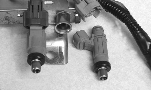
IGNITION TIMING SENSOR This sensor is triggered by teeth precisely mounted to the flywheel flange. Each time a tooth rotates past the sensor, a signal is sent to the ECM. From this signal, the ECM determines ignition and injection timing and RPM. BAROMETRIC PRESSURE SENSOR This sensor is part of the ECM. Its purpose is to sense atmospheric pressure. From this information, the ECM determines the correct fuel/air mixture ratio. FUEL INJECTORS A fuel injector is an electromagnetic injection valve controlled by a signal from the ECM. The coil used in the injector is a high-pressure resistance type. The ECM determines the optimum fuel injection time and duration based on signals from the sensors. When voltage is sent to the fuel injector, it energizes the coil and opens the needle valve, thereby injecting fuel. Because the fuel pressure (pressure differential between fuel line and manifold) is kept constant, the amount of fuel injected is determined by the duration of time the valve is open and manifold pressure.
Removing (5000/9000) WARNING
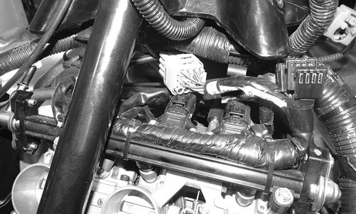
Since the fuel supply hose may be under pressure, remove it slowly to release the pressure. Place an absorbent towel around the connection to absorb gasoline; then remove the hose slowly to release the pressure. Always wear safety glasses when removing the fuel hoses. 1. Loosen the clamp securing the fuel supply hose to the fuel rail; then remove the hose from the fuel rail. 2. Disconnect the wiring harness from each injector. 3. Remove the screws securing the injector hold-down plate to the throttle body assembly; then remove the plate from the injectors. 4. Remove the fuel injectors from the throttle body/ intake manifold assembly.
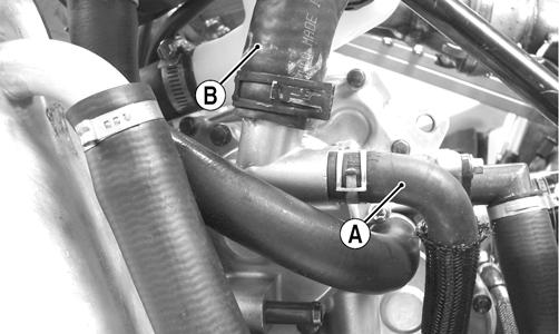
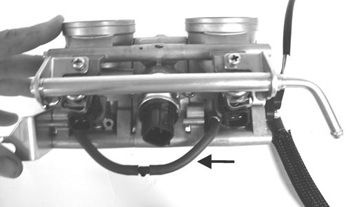
Installing (5000/9000) 1. Apply a light coat of oil to all O-rings; then install the upper and lower O-rings onto each injector. 2. Install the injectors into the throttle body assembly. 3. Place the injector hold-down plate into position on top of the injectors and secure with two screws. 4. Connect the fuel delivery hose to the fuel rail and secure with a clamp. NOTE: When securing the fuel delivery hose, position the clamp as shown.
SNO-369 4. Remove the fuel injectors from the throttle body assembly. Account for six grommets.
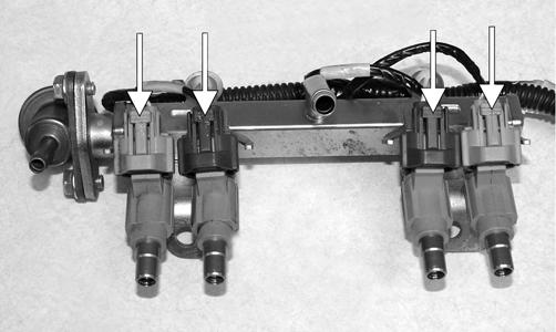
Installing (7000) 1. Apply a light coat of oil to all six grommets; then install onto each injector. 2. Install the injectors into the throttle body assembly. 3. Place the fuel rail into position on top of the injectors and secure with existing spacers, washers and cap screws.
5. Connect the wiring harness to the injectors. Removing (7000)
729-325
WARNING
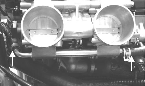
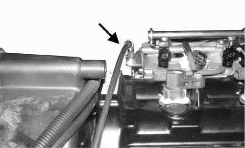
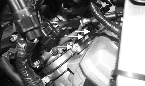
Since the fuel supply hose may be under pressure, remove it slowly to release the pressure. Place an absorbent towel around the connection to absorb gasoline; then remove the hose slowly to release the pressure. Always wear safety glasses when removing the fuel hoses. 1. Remove the orange clamp securing the fuel supply hose to the fuel rail. 2. Disconnect the wiring harness from each injector. 3. Remove the cap screws and washers securing the fuel rail to the throttle body assembly; then remove the rail from the injectors. Account for two washers and two spacers.
SNO-369 4. Connect the fuel delivery hose to the fuel rail and secure with the orange clamp. 5. Connect the wiring harness to the injectors. Cable tie as needed. FUEL PRESSURE REGULATOR The fuel pressure regulator maintains the fuel pressure at a constant specified level. The 9000 models maintain pressure from the manifold pressure. EXHAUST AIR TEMPERATURE (EAT) SENSOR This platinum, thin-film sensor detects the exhaust air temperature in the exhaust system. The ECM sends current to this sensor, and (depending on the temperature) the sensor will pass a portion of that current to ground. The ECM measures how much current passes through the sensor to ground. From this measurement, the ECM determines the exhaust air temperature and adjusts the fuel, ignition timing, and APV calibration. Resistance will increase as the temperature rises.
CRANKSHAFT POSITION SENSOR This sensor measures the location in degrees of rotation of the crankshaft. A 15° resolution exists between signals. The signal is triggered by teeth on the outer surface of the flywheel as they pass by the sensor. The sensor gives the ECM the location of the crankshaft at a given point in time. The ECM processes the information and uses it in many different types of calculations. For example, the sensor can be used for RPM, and it can also be used to determine the rate of acceleration of the crankshaft. CAMSHAFT POSITION SENSOR This sensor tells the ECM which stroke the engine is on. Because the 4-stroke engine operates on a 720° cycle, the piston is at TDC twice per cycle - once on the exhaust stroke and once on the compression stroke. MANIFOLD ABSOLUTE PRESSURE (MAP) SENSOR This sensor measures pressure in the intake manifold when the engine is running. The ECM uses this sensor to aid in calculating the required fueling. For the base fuel map, the 5000 relies on the MAP sensor only for low throttle openings. After a given throttle opening is reached, the ECM switches to the TPS sensor for its main fuel map. The 9000 relies entirely on the MAP sensor and only uses the TPS for its main fuel map if the MAP sensor should fail. The ECM uses the MAP sensor for many other calculations, but the base fuel map is the main one. WASTEGATE CONTROL VALVE (9000) The wastegate control valve adjusts the wastegate position based on input from the ECM. The wastegate does not require any input from the ECM to operate at base boost levels. In areas of operation where the ECM will allow the turbocharger to exceed base boost, the wastegate control valve bleeds some of the pressure that would typically be used to open the wastegate via the wastegate diaphragm port on the turbocharger. By bleeding this pressure, the wastegate is set at a lower opening thereby allowing more exhaust gas to pass by the turbine increasing the boost level. KNOCK SENSOR This sensor controls engine knock or detonation. The knock sensor assesses structure borne noise (vibrations) caused by rapid pressure rises (detonation) in either cylinder and performs calibration adjustments to the necessary cylinder via the ECM limiting damage to internal engine components. Detonation can be caused by many variables including poor fuel quality, lean operating conditions, or modified engine components/systems.
Self-Diagnostic System/ Codes
5000/9000
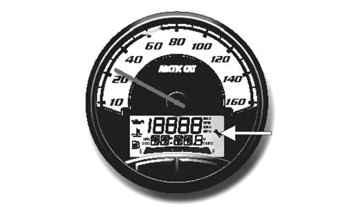
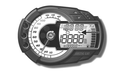
NOTE: For testing the EFI system, refer to the EFI Diagnostic System Manual with Laptop Diagnostic Tool and Laptop Diagnostic Test Kit. INTRODUCTION The Service Icon is controlled by the ECM. The icon should illuminate each time the engine is started, and it should go out after a few seconds. If the icon stays illuminated while the engine is running and a code is displayed on the readout screen, the ECM is receiving input that is outside of its established parameters. Refer to the following chart.
Deluxe Gauge
Standard Gauge
FZ001D
FZ003B
Code Trouble 1 Failure in the fuel system. 2 Failure in injector (PTO). 3 Failure in injector (MAG). 4 Failure in barometric pressure sensor circuit. 5 Open or short circuit in intake manifold air temperature sensor circuit. 6 Open or short circuit in water temperature sensor circuit. 7 Open or short circuit in throttle position sensor circuit. 8 Open or short circuit in manifold air pressure sensor circuit. 9 Failure in crankshaft position sensor circuit. 11 Failure in speed sensor circuit. 12 Failure in coil (MAG). 13 Failure in coil (PTO). 14 Failure in ISC valve. 15 Failure in oxygen sensor circuit. 19 Failure in camshaft position sensor circuit. 21 Open or short circuit and/or loose knock sensor circuit. 22* Failure in injector (PTO secondary). 23* Failure in injector (MAG secondary). 25 Failure in shifting system/gear position switch. 26 Malfunction in air pressure sensor circuit. 29 Malfunction in shift control switch. OCTN* Low octane gasoline. *9000 only
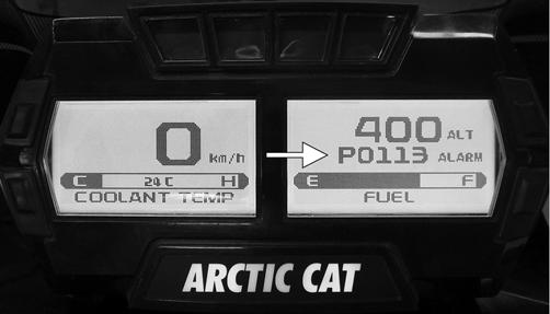
The fuel system and the ignition system remain two separate systems. In a no-start situation, first determine if the problem is caused by lack of spark or by a fuel delivery problem or by an internal engine condition (low cylinder compression for example). Once the problem area has been determined, check the components involved using the Fluke Model 77 Multimeter or the EFI Analyzer depending on the test being made. 7000 The Diagnostic Code Alarm is controlled by the ECM. If a code and the word ALARM illuminates while the engine is running, the ECM is receiving input that is outside of its established parameters. Refer to the following chart.
CWI-105A P1686 Main relay circuit low P1688 Reverse relay open circuit P1689 Reverse relay circuit low P1691 Forward relay open circuit P1692 Forward relay circuit low P1694 Headlight relay open circuit P1695 Headlight relay circuit low P2228 Barometric pressure sensor A circuit low P2229 Barometric pressure sensor A circuit high P2300 Ignition coil A primary control circuit low P2303 Ignition coil B primary control circuit low P2306 Ignition coil C primary control circuit low U1000 Vehicle not registered or invalid PIN U1001 Vehicle not registered and vehicle limits enabled U0155 Lost communication with the ECM
Code Trouble P0031 O2 Heater Control Circuit Low P0032 O2 Heater Control Circuit High P0107 Manifold absolute pressure circuit low P0108 Manifold absolute pressure circuit high P0112 Intake air temp sensor circuit low P0113 Intake air temp sensor circuit high P0115 Engine coolant temp sensor 1 circuit P0117 Engine coolant temp sensor 1 circuit low P0118 Engine coolant temp sensor 1 circuit high P0120 Throttle position sensor circuit P0122 Throttle position sensor circuit low P0123 Throttle position sensor circuit high P0130 O2 sensor circuit P0131 O2 sensor circuit low P0132 O2 sensor circuit high P0171 System too lean P0172 System too rich P0201 Injector circuit/open - cylinder 1 P0202 Injector circuit/open - cylinder 2 P0203 Injector circuit/open - cylinder 3 P0217 Engine coolant over temp condition P0261 Cylinder 1 injector circuit low P0264 Cylinder 2 injector circuit low P0267 Cylinder 3 injector circuit low P0508 Idle air control system circuit low P0509 Idle air control system circuit high P0511 Idle air control circuit P0522 Engine oil pressure sensor circuit low P0523 Engine oil pressure sensor circuit high P0562 System voltage low P0563 System voltage high P0780 Shift Error P1315 Crankshaft Position out of sync P1338 Crankshaft spike detected P1339 Crankshaft tooth not detected P1685 Main relay open circuit
Fuel Pressure Regulator
1. Using the Fuel Pressure Test Kit, connect the tester to the regulator fuel inlet. NOTE: A short piece of 3/8 in. I.D. hose will be needed to make the above connections.
2. Pressurize the regulator to 28-31.3 psi. Turn the pressure tester shut off valve to the OFF position.
Observe the gauge for several minutes and note any loss of pressure. If pressure begins to drop, the cause may be a ruptured diaphragm, worn spring, or leaking valve. If the regulator fails to build or maintain pressure, replace the regulator. NOTE: If the pressure drops, check the hose connections to ensure no leaks exist.
Throttle Body Assembly
REMOVING/DISASSEMBLING (5000) NOTE: To remove the throttle body assembly, it is necessary to remove the air silencer. The seat and gas tank must also be removed. 1. Remove the coolant hoses and MAP sensor hoses from the throttle body.
ZJ018A
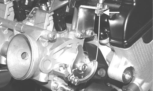
ZJ289A 2. Loosen the throttle cable jam nut; then remove the throttle cable from the bracket and the throttle valve cam.
ZJ103A 3. Remove the cable ties securing the fuel injector wiring harness to the fuel rail; then disconnect the harness from the fuel injectors. NOTE: For installing purposes, note the location of all cable ties.
4. Loosen the clamps securing the throttle bodies to the intake boots; then remove the throttle body assembly. 5. Remove the retaining clips securing the fuel rail to the injectors; then remove the two screws securing the fuel rail to the throttle body assembly. Remove the fuel rail and injectors from the throttle body assembly.
ZJ290
NOTE: For assembling purposes, note from which side the fuel injectors were removed. ASSEMBLING/INSTALLING (5000) 1. Install the fuel injectors onto the throttle body assembly; then secure the fuel rail and injectors to the throttle body assembly with the two screws and the retaining clips.
ZJ291A
ZJ290 2. Install the throttle body assembly to the intake boots and tighten the clamps; then install the coolant hoses and the MAP sensor hoses. Secure the coolant hoses with the clamps. 3. Connect the injector wiring harness to the injectors; then secure the harness to the fuel rail with cable ties in the proper locations as noted during disassembling. 4. Install the throttle cable to the bracket on the throttle body assembly and to the throttle valve cam; then secure the cable with the jam nut.
ZJ103A
NOTE: To finalize this procedure, install the air silencer. Install the gas tank and seat.
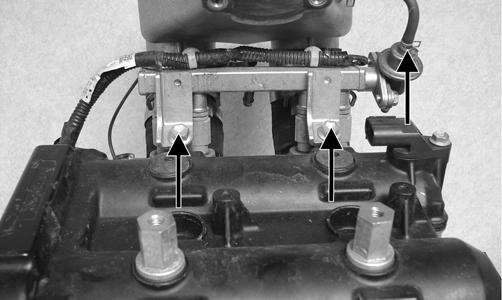
REMOVING/DISASSEMBLING (9000) 1. Remove the hood, seat, and gas tank. 2. Disconnect the throttle cable (A); then disconnect the idle speed control (B).
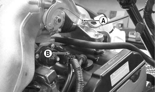
TZ108A 3. Remove the harness connector from the throttle position sensor (A); then place a towel under the throttle body coolant hoses (B) and with a suitable clamping device, close-off the coolant hoses and remove them from the throttle body.
TZ075B
NOTE: If the snowmobile is in warranty, breaking the seal on the idle screw jam nut or the Phillips-head screws on the TPS will void warranty. 4. Remove the four cap screws securing the throttle body to the intake manifold and account for the throttle cable support bracket.
TZ109A 5. Remove the four screws securing the ISC valve to the throttle body.
TZ110A
NOTE: Remove the throttle body ISC valve before using any type of cleaner to clean the throttle body. 6. Using a throttle body cleaner, spray throttle valve once and clean the venturi of carbon buildup. A fine nylon brush may be needed to clean carbon deposits.
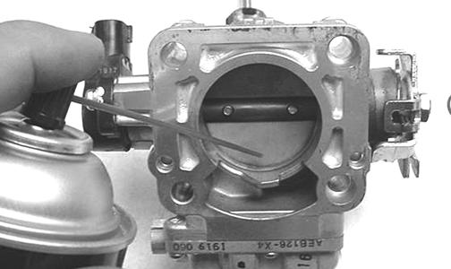
AO252
CAUTION
Never place the throttle body in cleaning solvent with the TPS secured to the throttle body or the sensor must be replaced. 7. Carefully blow-dry the throttle body and be sure that the ISC valve rubber gasket is properly placed for assembly. 8. Disconnect the injector harness and remove the hose from the fuel pressure regulator; then remove the cap screws securing the fuel rail/injectors to the intake flange.
TZ111A
NOTE: After removing the fuel rail, account for the four injector gaskets.
TZ113
NOTE: With the injectors removed, inspect the Orings and gaskets for damage.

TZ113A 10. If necessary, remove the cap screws securing the fuel pressure regulator to the fuel rail and remove the regulator. ASSEMBLING/INSTALLING (9000) 1. If removed during disassembling, install the fuel pressure regulator with a new O-ring in place and secure it to the fuel rail. Tighten to 96 in.-lb. 2. Install the injectors into the fuel rail; then install the four harness connectors to the injectors and connect the injector harness to the main harness connector.
TZ116A 3. Install new injector gaskets into the intake flange and install the fuel rail/injectors. Secure with the two cap screws and tighten to 18 ft-lb; then install and secure the hose to the fuel pressure regulator.

TZ117
TZ111A 4. With a new gasket for the ISC valve in place, secure the ISC valve to the throttle body and tighten securely.
TZ110A 5. With a new throttle body gasket, secure the throttle body with the cable support bracket to the intake plenum with the four caps screws; then tighten to 18 ftlb.
6. Install the hose connecting the intake pipe to the throttle body and secure with the hose clamps. 7. Install the coolant hoses to the throttle body and secure with the clamps; then install the harness connector to the throttle position sensor. 8. Install the harness connector to the idle speed control (B); then install the throttle cable to the throttle body pulley and secure the cable with the jam nut (A).
TZ108A
NOTE: Make sure the throttle cable is secured correctly so the cable does not rub on the steering post.
SNO-741A
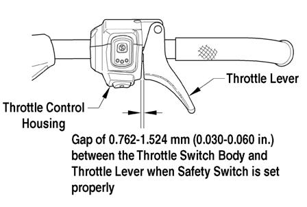
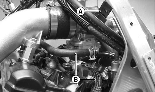
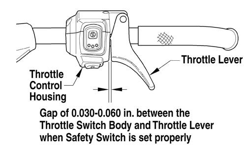
NOTE: Make sure the throttle lever free-play is within a range of 0.030-0.060 in. 9. Install the gas tank and seat; then install the hood and side panels. Connect the hood harness. REMOVING/DISASSEMBLING (7000) NOTE: To remove the throttle body assembly, it is necessary to remove the access panels, hood, air intake assembly, and the two front spars. 1. Remove the coolant hoses and MAP sensor hoses from the throttle body.
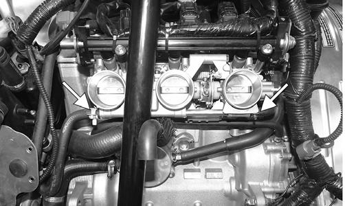
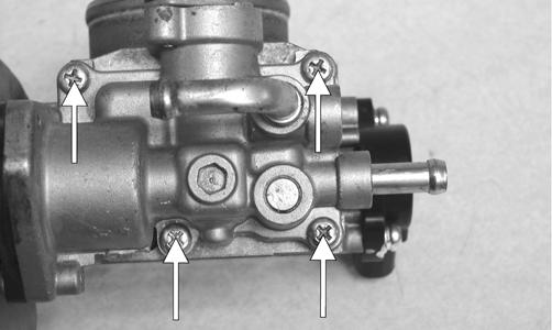
YM-043A 2. Disconnect the throttle body harness from the main harness; then loosen the three screws securing the throttle body to the intake boots.
YM-044A 3. Loosen the throttle cable jam nut; then remove the throttle cable from the bracket and the throttle valve cam. Remove the throttle body. 4. Remove the cable ties securing the throttle body harness to the fuel rail.
YM-045A
NOTE: For installing purposes, note the location of all cable ties.
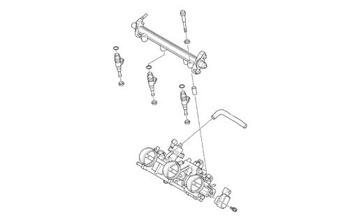
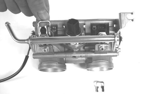
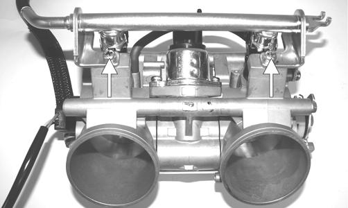
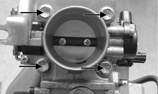
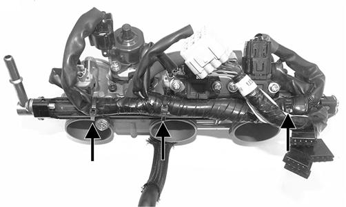
5. Remove the screws and washers securing the fuel rail to the throttle body; then remove the injectors.
Account for six O-rings.
YM-047A
YM-048A
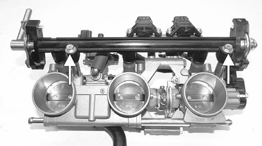
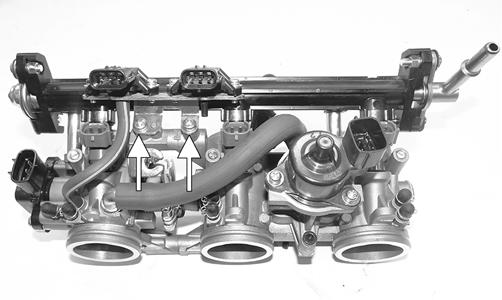
NOTE: For assembling purposes, note from which side the fuel injectors were removed. ASSEMBLING/INSTALLING (7000) 1. Install the fuel injectors onto the throttle body assembly; then secure the fuel rail and injectors to the throttle body assembly with the four screws, washers and spacers. Tighten securely.
YM-047A YM-048A 2. Connect all connections of the throttle body harness to the throttle body sensors. Secure the harness to the fuel rail using cable ties.
YM-045A 3. Install the throttle cable to the bracket on the throttle body assembly and to the throttle valve cam; then secure the cable with the jam nut. 4. Install the throttle body assembly to the intake boots and tighten the clamps; then install the coolant hoses and the MAP sensor hoses. Secure the coolant hoses with the clamps.
YM-044A
YM-043A 5. Connect the large gray connector to the main harness.
YM-049
NOTE: To finalize this procedure, install the front spars, air silencer, hood and both access panels.
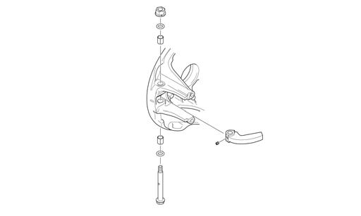
Throttle Cable
REMOVING 1. Loosen the throttle cable from the bracket; then remove the throttle cable from the pulley on the throttle body lever shaft. 2. Remove the cable ties securing the throttle cable. 3. Remove the throttle cable ends from the throttle lever and from the throttle control housing. INSTALLING/ADJUSTING 1. Install the throttle cable into the throttle control assembly making sure the cable snaps into place. 2. Install the throttle cable end on the throttle lever. 3. Route the throttle cable from the throttle control assembly to the throttle body assembly and oil-injection pump; avoid any sharp bends or moving components. 4. Attach the throttle cable to the pulley on the throttle body shaft. 5. Secure the throttle cable to the handlebar and steering post with cable ties. 6. Adjust the throttle cable tension by turning the jam nuts in the appropriate direction until 0.030-0.060 in. free-play exists in the throttle lever and the butterfly completely opens and closes. Tighten the jam nuts securely.
741-518A
CAUTION
Compress the throttle control lever to ensure free movement. If the throttle cable sticks or binds, correct the problem before starting the engine.
7. Synchronize the oil-injection pump (see Oil-Injection Pump in this section).
Fuel Filter
NOTE: The fuel filter should be replaced every 5000 miles.
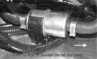
NOTE: Before removing the fuel filter, take note of the filter inlet and outlet for installing purposes. REMOVING WARNING
Since the fuel supply hose may be under pressure, remove it slowly to release the pressure. Place an absorbent towel around the connection to absorb gasoline; then remove the hose slowly to release the pressure. Always wear safety glasses when removing the fuel hoses.
1. Remove both access panels, hood, and seat to access the fuel filter. NOTE: On the 9000, the gas tank must be removed.
SNO-700A

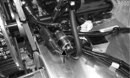
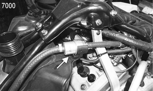
XM184B 2. Disconnect the gasline hose from the fuel pump. 3. Remove the hose clamps and discard; then slowly remove the fuel hoses from the fuel filter. Dispose of the excess fuel from the filter properly. NOTE: Inspect the hoses for any signs of cracking, cuts, or wear points. Replace if necessary. INSTALLING 1. Place new hose clamps on the gasline hoses; then with the fuel pump inlet and outlet oriented correctly, connect the gasline hose to the fuel pump. NOTE: On the 9000, insert the filter making sure the lip sits between the tab and clamp.
SNO-1021 2. Install the gas tank (9000), seat, hood, and access panels; then start the engine and inspect the gasline hoses and filter for any signs of leaks. 3. Secure the fuel filter to the fuel filter bracket; then start the engine and inspect the fuel hoses and filter for any signs of leaks. 4. Close the left-side access panel. TESTING 1. Remove the seat assembly; then remove the upper and lower console panels. 2. Disconnect the gasline hose connector hose from the outlet of the fuel pump by pressing inward on the white connector, pressing in the black release, and finally pulling back on the hose.
WARNING
Since the fuel supply hose may be under pressure, remove it slowly to release the pressure. Place an absorbent towel around the connection to absorb gasoline; then remove the hose slowly to release the pressure. Always wear safety glasses when removing the fuel hoses.
PC031B
YM-050A 3. Connect Fuel Pressure Test Kit to the fuel pump and fuel hose. 4. Turn the ignition key to the ON position. Fuel pressure should be as specified.
5000/7000 9000 43.5 psi 36.0 psi - Idle 55.0 psi - Full Boost
NOTE: If fuel pressure is not as specified, the pump is defective and must be replaced. 5. Disconnect the fuel pump from the main wiring harness.
6. Connect the positive lead of a 12-volt power supply to the red wire and the negative lead of the 12-volt power supply to the black wire. 7. The pump should operate (it would be heard running). NOTE: If the fuel pump fails to operate, reverse the power supply at the fuel pump connector allowing the motor to run in the opposite direction. This will verify that nothing has entered and/or obstructed the pump.
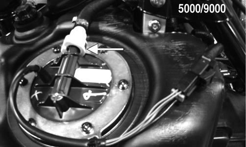
NOTE: If the fuel pump still fails to operate, the pump is defective and must be replaced. REMOVING (5000/9000) 1. Remove both access panels, hood, upper and lower consoles, and seat. 2. Disconnect the fuel pump harness connector; then disconnect the gasline hose from the outlet of the fuel pump by pressing inward on the white connector, pressing in the black release, and finally pulling back on the hose.
3. Remove and retain the six torx-head screws securing the fuel pump in the fuel tank; then remove the retaining ring. 4. Carefully remove the fuel pump and fuel pickup assembly from the gas tank noting the orientation of the fuel pump outlet for assembling purposes.
WARNING
Since the fuel supply hose may be under pressure, remove it slowly to release the pressure. Place an absorbent towel around the connection to absorb gasoline; then remove the hose slowly to release the pressure. Always wear safety glasses when removing the fuel hoses.
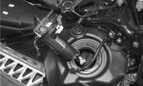
SNO-702

NOTE: If the fuel pickup assembly is not being replaced, inspect the screens for any tears or obstructions. Also check the hoses and replace if necessary. INSTALLING (5000/9000) 1. Slide Fuel Pump Installation Tool onto the fuel hose near the “Y” fitting until the tool touches the middle pickup. The two rear pickups should be pulled together.
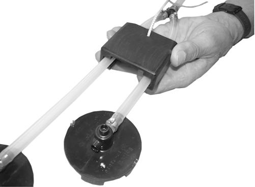
SNO-704 2. Carefully push the fuel pump assembly down and back into the fuel tank until the white fuel sensor (below the fuel pump) is flush with the fuel pump mounting surface.
SNO-705 3. While holding the fuel pump with the white fuel sensor in this position, pull the tool up to the tank opening with the retrieval cord.
SNO-744
NOTE: Tip the fuel pump assembly to one side enough to allow the tool to be removed.
NOTE: When the fuel pump hose assembly is installed correctly, the two rear pickups will lie flat in the rear of the fuel tank.
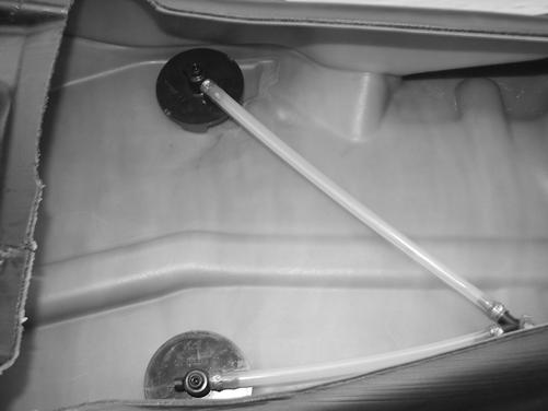
SNO-791 4. Make sure the front pickup will sit flat on the bottom of the tank with no kinks in the fuel hose.
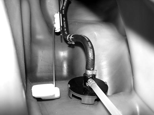
SNO-706 5. Install the retaining ring over the fuel pump and secure the fuel pump to the gas tank assembly using the existing torx-head screws. Tighten to 40 in.-lb.
6. Connect the fuel pump harness connector to the main harness and secure to the retaining ring with a cable tie; then secure the gasline hose to the fuel pump making sure it locks into place. 7. Install the upper and lower consoles using existing machine screws; then install the seat, hood, and access panels. REMOVING (7000)
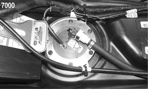
1. Remove the seat; then disconnect the fuel pump harness connector; then disconnect the gasline hose from the outlet of the fuel pump by pressing inward on the white connector, pressing in the black release, and finally pulling back on the hose. Remove both cable ties secured to the fuel pump ring.
CAUTION
Use care not to over tighten the retaining plate screws or damage to the gas tank may result.
CAUTION
Before removing the fuel pump of fuel level sensor from the gas tank, be sure the fuel level is low or fuel may leak from the gas tank.
YM-050A
WARNING
Since the fuel supply hose may be under pressure, remove it slowly to release the pressure. Place an absorbent towel around the connection to absorb gasoline; then remove the hose slowly to release the pressure. Always wear safety glasses when removing the fuel hoses.
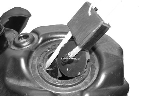
2. Remove and retain the six torx-head screws securing the fuel pump in the fuel tank; then remove the retaining ring. 3. Carefully remove the fuel pump and fuel pickup assembly from the gas tank noting the orientation of the fuel pump outlet for assembling purposes.
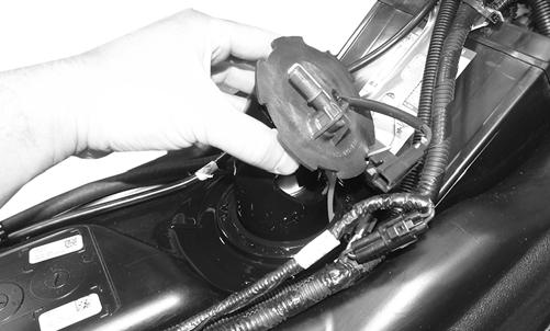
YM-051
NOTE: If the fuel pickup assembly is not being replaced, inspect the screens for any tears or obstructions. Also check the hoses and replace if necessary. INSTALLING (7000) 1. The two fuel pickups should be pressed together then carefully slide into the fuel pump opening in the gas tank; then install the fuel pump and orientate it so the fuel hose connection faces the front right of the snowmobile.
YM-051 2. Install the retaining ring over the fuel pump and secure the fuel pump to the gas tank assembly using the existing torx-head screws. Tighten to 40 in.-lb. 3. Connect the fuel pump harness connector to the main harness and secure to the retaining ring with a cable tie; then secure the gasline hose to the fuel pump making sure it locks into place. Secure the cables to the fuel pump ring using two cable ties.
CAUTION
Use care not to over tighten the retaining plate screws or damage to the gas tank may result. 4. Install the seat.
YM-050A
Troubleshooting
Problem: Too Rich Condition Remedy 1. Diagnostic trouble code activated 1.Replace problem sensor 2. Fuel pressure too high 2.Replace regulator 3. Fuel return hose obstructed 3.Service - replace hose - remove obstruction 4. Injectors leaking 4.Replace injectors Problem: Too Lean Condition Remedy 1. Diagnostic trouble code activated 1.Replace problem sensor 2. Fuel pressure too low 2.Replace regulator/fuel pump 3. Vent hose obstructed 3.Remove obstruction 4. Fuel filter(s) obstructed 4.Replace fuel filter(s)
Gas Tank
REMOVING 1. Remove the access panels, hood, and the seat. 2. Remove the lower console. 3. Disconnect the reverse alarm; then remove the two machine screws securing the upper console. 4. Remove and retain all four cap screws securing the rear spar tubes to the chassis and steering support. 5. Disconnect the gasline hose, vent hose, and fuel pump harness. Remove the gas tank. NOTE: On 7000 models, the battery cables and the battery will have to be removed. INSTALLING 1. Install the gas tank; then connect the gasline hose, vent hose, and fuel pump harness. 2. Install the rear spar tubes and secure to the chassis and steering support using the four cap screws.
Tighten to 23 ft-lb. 3. Connect the reverse alarm; then use the two machine screws to secure the upper console. 4. Install the lower console; then install the access panels, hood, and seat.