Steering and Body This section has been organized into sub-sections for servicing steering and body components; however, some components may vary from model to model. The technician should use discretion and sound judgment when removing and installing components. NOTE: Whenever a part is worn excessively, cracked, or damaged in any way, replacement is necessary.
SPECIAL TOOLS
0744-927
A special tool must be available to the technician when servicing the steering and body systems. Description
p/n
Shock Spring Removal Tool
0644-057
Handlebar Stand
5639-152
Steering Post Stand
5639-946
NOTE: Special tools are available from the Arctic Cat Service Parts Department.
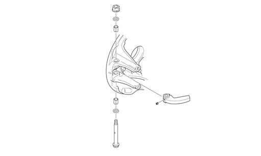
5. On the LXR models, unlock the cam lever and unthread the lever from the lock rod (B); then remove the lock rod and account for the two bottom cap springs (C).
CAUTION Do not rotate the handlebar to a position allowing air to enter the brake system.
6. Remove the four cap screws securing the upper bearing bracket to the upper support plate.
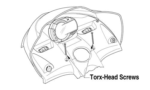
Steering Post REMOVING 1. Open the hood; then remove the two torx-head screws securing the console to the headlight support bracket.
FS182A
7. On the Bearcat 570/F-Series/T-Series, remove the springs securing the expansion chamber; then remove the expansion chamber from the engine compartment. Account for the rubber exhaust bumper.
0743-777
2. Lift the rearward end of the console and disconnect the main/hood harness connector; then remove the console. 3. On the standard models, remove the four cap screws, lock nuts, and adjuster block caps securing the handlebar/riser assembly to the steering post; then lay the handlebar/riser assembly aside. Account for the lower adjuster block. 4. On the LXR models, remove the two screws from the handlebar pad; then remove the self-tapping screw securing the retainers (A) to the riser block assembly. Remove the retainer.
FS203A
8. On the TZ1, remove the two cap screws (A) securing the front end close-off cover to the chassis.
259