Fuel/Lubrication This section has been organized for servicing the fuel system. The technician should use discretion and sound judgment when removing/disassembling and assembling/ installing components.
! WARNING Whenever any maintenance or inspection is made on a fuel system when there may be fuel leakage, there should be no welding, smoking, open flames, etc., in the area.
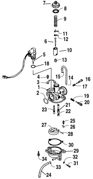
Carburetor Schematic KEY 1. 2. 3. 4. 5. 6. 7. 8. 9. 10. 11. 12. 13. 14. 15. 16. 17. 18. 19. 20. 21. 22. 23. 24. 25. 26. 27. 28. 29. 30. 31. 32. 33. 34.
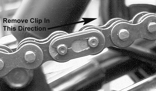
Carburetor Body O-Ring Set Plate Screw w/Washer Choke Assembly Jet Needle Carburetor Cap Gasket Throttle Valve Spring Throttle Valve Needle Clip Plate Needle Clip Needle Jet Vent Hose Clip Idle Adjustment Screw Spring O-Ring Spring Pilot Screw Jet Holder Main Jet Slow Jet Float Chamber Drain Hose Needle Valve Clip Float Assembly Float Pin Float Chamber Gasket Drain Screw O-Ring Clip Screw w/Washer
CD590
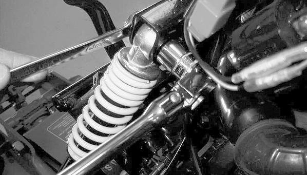
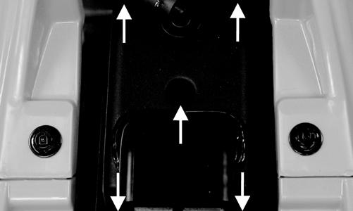
2. Disconnect the float chamber drain hose and the vent hose from the carburetor. 3. Remove the air intake boot.
CD589
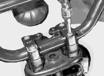
4. Remove the cap screws securing the carburetor to the intake manifold; then remove the carburetor.
CD592
741-045A
5. Unscrew the carburetor cap; then lift the cap removing the throttle valve, spring, and jet needle. Account for a gasket, a needle clip plate, and a needle clip.
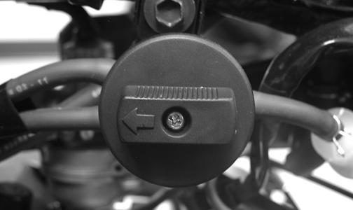
Carburetor REMOVING 1. Turn the gas tank valve to the OFF position; then disconnect the gas hose from the carburetor.
45