19 minute read
CONTROLS, COMPONENTS AND INSTRUMENTS FUNCTIONS

from 2003 Seadoo GTI GTI California GTI LE GTI LE RFI RX DI GTX DI Operator’s Guide Manual – PDF DOWNLOAD

1)Safety Lanyard (engine cut-off cord)
The safety lanyard cap should be securely snapped onto its post to be fully operational. Pulling the safety lanyard cap from its post stops the engine operation. Attach the safety lanyard to the operator’s Personal Flotation Device (PFD) and snap the cap to the post to be able to start the engine.
Two short beeps indicates the system is ready to allow engine starting. Otherwise, refer to the TROUBLESHOOTING section for the coded signals chart.
WARNING
While engine can be stopped using the engine start/stop button, good habits recommend that the safety lanyard also be disconnected when stopping.
1. Safety lanyard cap on the post 2. Safety lanyard secured on operator’s PFD
WARNING
Should the engine be stopped, watercraft directional control is lost (reduced on models with O.P.A.S.TM). Always disconnect safety lanyard when watercraft is not in operation in order to prevent accidental engine starting or to avoid unauthorized use by children or others or theft.
If engine is not started within 5 seconds after installing the safety lanyard on its post, 4 short beeps every 3 second interval will sound for approximately 2 hours to remind you to start the engine or to remove safety lanyard. Afterwards, the beeps will stop. The same will occur when safety lanyard is left on its post 5 seconds after engine is stopped. Always ensure safety lanyard is not left on its post after engine is stopped. IMPORTANT: Leaving the safety lanyard on its post when engine is not running will slowly discharge the battery.
Digitally Encoded Security System (DESS)
The safety lanyard cap specifically contains an electronic circuit that gives it a unique electronic serial number. This is the equivalent of a conventional key. This safety lanyard cannot be used on another watercraft and conversely, the one from another watercraft cannot be used on your watercraft. However, the DESS brings a great flexibility. You can buy an additional safety lanyard and have it programmed for your watercraft.
The DI models also offers a special safety lanyard — the SEA-DOO LKTM (SEA-DOO Learning KeyTM) — which electronically limits the speed of the watercraft to approximately 55 km/h (35 MPH) therefore enabling first time users and less experienced operators to learn how to operate the watercraft while gaining the necessary confidence and control.
To have additional safety lanyard, refer to an authorized SEA-DOO dealer.

WARNING
While engine can be stopped using the engine start/stop button, good habits recommend that the safety lanyard also be disconnected when stopping.
2)Handlebar
The handlebar controls the direction of the watercraft. Turning the handlebar to the right steers the watercraft to the right and inversely. WARNING
Check handlebar and corresponding steering nozzle and side vanes (if so equipped) operation before starting. Never turn handlebar while someone is nearby rear of watercraft. Keep away from steering moving parts (nozzle, side vanes, linkage etc.). When the throttle lever is squeezed, the watercraft accelerates. When fully released, engine automatically slows down to idle speed and watercraft is gradually stopped by water drag.
Carburetor-Equipped Models
Do not depress lever unnecessarily when engine is not running. A fuel accelerator pump delivers fuel to the engine each time throttle lever is applied. CAUTION: Engine can be flooded if throttle lever is unnecessarily applied several times. If engine is flooded, it will not start. Refer to SPECIAL PROCEDURES for instructions.
4)Engine Start/Stop
Button
All Models
To start engine, depress and hold the start/stop button. Release immediately after engine is started. To stop engine, fully release throttle lever then depress the start/stop button and disconnect safety lanyard from the post.
WARNING
On models without O.P.A.S. directional control is reduced when the throttle is released and lost when engine is off.
WARNING
On models with O.P.A.S. directional control is reduced when the throttle is released or when engine is off.
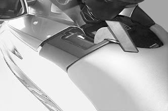
1. Engine start/stop button
GTX DI Models
1. Engine Start/Stop button
5)Variable Trim System (VTS) Button (if so equipped)
Located just below engine start/stop button, this button is used to change pump jet nozzle position and to adjust ride to suit watercraft load and water conditions.
1. VTS button
A VTS position indicator is included in the information center gauge. See elsewhere in this section.
Carburetor-Equipped Models
The choke is provided to supply a richer fuel/air mixture when starting a cold engine. Choke lever should be pulled and held to operate. Lever will automatically return to its normal position when released.

1. Choke lever
7)Shift Lever
A push-pull lever: – forward – neutral – reverse. WARNING
Shift lever should only be used when the engine is idling and craft is completely stopped. Do not use as a grab handle.
WARNING
Only use reverse at slow speed and for the shortest time possible. Always ensure the path behind is clear of objects and persons including children playing in shallow water.
CAUTION: Never rev the engine at high RPM in reverse.
From the forward position, pull the lever to reverse. Push back to go to forward. Always set in forward when finished. To find the neutral, set in reverse then push back until the watercraft stops moving backwards.

FORWARD POSITION

NEUTRAL POSITION
REVERSE POSITION
8)Fuel Gauge/Low Oil
Warning Light (if so equipped)
Analog gauge indicates the amount of fuel in the fuel tank and a warning light turns on when level is low in oil reservoir.
1. Low oil warning light
9)Speedometer (if so equipped)
Analog speedometer indicates the speed of watercraft in miles per hour (MPH) and kilometers per hour (km/h). The speed sensor mounted on the ride plate sends the signal to the speedometer and information center (if so equipped).
10)Tachometer (if so equipped)
An analog tachometer indicates the revolutions per minute (RPM) of the engine. Multiply by 1000 to obtain the actual revolutions.
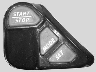
This is a LCD multifunction gauge. Different displays and functions can be activated using 2 buttons — MODE and SET — following specific sequences as described below.
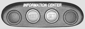
1. To change display mode 2. To set or reset a function
NOTE:Some models have the MODE and SET buttons at a different location and differ in appearance. However, the functionality is the same. The following explanations apply to both types of buttons.
1. To change display mode 2. To set or reset a function
Resetting a Function To reset a function (such as the chronometer, distance, etc.) press and hold the SET button for 2 seconds while in the appropriate mode. The information center includes the following display areas.

1. General display 2. Message/units display 3. Warning light 4. Fuel level display 5. VTS position indicator (if so equipped)
General Display
Repeatedly pressing the MODE button scrolls the following displays: Compass (if so equipped), Tachometer, speedometer, average speed, trip meter, hourmeter, water temperature, exterior temperature (if so equipped) and chronometer.
1. Press to change display mode
When you are satisfied with your choice, stop pressing the button.The display you have chosen will remain until it is changed. When safety lanyard is installed, the last chosen display will come back.
Compass (if so equipped): Displays the cardinal points to indicate the orientation of the watercraft. WARNING
Use the compass as a guide only. Not to be used for navigation purposes.
Tachometer: Indicates the revolutions per minute (RPM) of the engine. Speedometer: Indicates the speed of watercraft in kilometers per hour (KPH) or miles per hour (MPH). Average Speed: The information center approximately calculates and displays the average speed (AV KPH or AV MPH) of the watercraft since the last engine start. Trip Meter: The information center approximately calculates the distance based on the operation time and the watercraft speed and displays the result in kilometers (KM) or miles (MILES). Hourmeter: Displays the time in hours of the watercraft usage. Water Temperature: Displays the water temperature you are on (L TEMP) in degrees Celsius (°C) or Fahrenheit (°F). Exterior Temperature (if so equipped): Displays the exterior air temperature (E TEMP) in degrees Celsius (°C) or Fahrenheit (°F). Chronometer: Allows to measure an interval of time in hours and minutes (hh:mm).
Message Display
The information center features a display area that blinks a message whenever one of the following circumstances occurs: • fuel injection system sensors and major components (MAINT) (DI models) • compass error (COMPAS) (if so equipped) • maintenance (MAINT) • engine overheating (H-TEMP) • low fuel (FUEL-LO) • low oil (OIL LOW) • low voltage (12 V LOW). A buzzer will sound when one of the four last circumstances occurs. Except for low fuel and low oil, which can be corrected by refilling, it is recommended to see an authorized SEA-DOO dealer when other messages occur. The warning light will blink at the same time.
Warning Light
The red warning LED (Light-Emitting Diode) blinks along with the message display to catch your attention.
Fuel Level Display
Bar gauge continuously indicates the amount of fuel in the fuel tank while riding. A low-fuel condition is also indicated when it occurs. See MESSAGE DISPLAY above.
VTS Position Indicator (if so equipped)
The VTS position indicator shows the riding angle of the watercraft.

1. Position indicator 2. Bow up 3. Bow down
Display Priorities
As a self test, all LCD segments and the LED will turn on for 3 seconds each time the information center is activated (when safety lanyard is installed). When the information center is activated, the last function set will be displayed if it was the tachometer, speedometer or chronometer. If another function was set, the compass will be displayed. On models without the compass function, the word “SeaDoo” will be displayed. In the event of a warning message, the message will blink and override the units display. If more than one warning message occurs, the blinking messages will scroll every 4 seconds.
Other Functions
The following describes how to select other available functions. Language Option While in the compass mode (while “SeaDoo” is displayed on models without compass):
1. Press and hold for 2 seconds
1. Repeatedly press 1. Press to end
English/Metric System Allows to display the units in the metric system or in the SAE English system.
1. Press TOGETHER and hold for 2 seconds
Chronometer While in the chronometer mode:
1. Press to start or stop chronometer
1. Press and hold for 2 seconds to reset
Chronometer is reset every time engine is turned off.
Maintenance Information When the watercraft is due for a maintenance inspection, the message MAINT will blink. To clear the warning message while it is blinking:
1. Press and hold for 2 seconds to reset
NOTE: If maintenance message (MAINT) continues to blink, it indicates a fault with the fuel injection system on Di models. Refer to an authorized SEA-DOO dealer for servicing.
12)Glove Box
A small, convenient storage compartment for personal articles.
13)Fuel Tank Valve
Carburetor-Equipped Models

1. ON 2. OFF
A 3-position rotating valve: OFF, ON and RESERVE: OFF:Stop fuel supply to carburetor(s). CAUTION: Turn valve to OFF position when watercraft is not operated. ON: Allows fuel to flow to carburetor(s). This is the normal position for operation of watercraft. CAUTION: Improper opening of fuel valve may restrict flow of fuel and may lead to engine damage. Make sure valve is fully opened while running. RES (RESERVE): Use when the watercraft has run out of fuel in the ON position. Always refill the fuel tank at the first opportunity. After refueling, turn the fuel tank valve to the ON position to continue operation.
14)Fuel Tank Cap
Some Models
Open the front storage compartment cover to expose fuel tank cap.
All Models
Refer to the vehicle illustration for fuel tank cap location. Unscrew the cap counterclockwise. After fueling, reinstall cap and fully tighten. WARNING
Always stop the engine before refueling. Fuel is inflammable and explosive under certain conditions. Always work in a well ventilated area. Do not smoke or allow open flames or sparks in the vicinity. Fuel tank may be pressurized, turn cap slowly when opening. Never use an open flame to check fuel level. When fueling, keep watercraft level. Do not overfill or top off the fuel tank and leave watercraft in the sun. As temperature increases, fuel expands and might overflow. Always wipe off any fuel spillage from the watercraft. Periodically verify fuel system. Always turn the fuel tank valve (if so equipped) to OFF position when the watercraft is not in use.
15)Oil Injection Reservoir
Cap
Refer to the vehicle illustration for oil injection reservoir cap location. To add injection oil in the reservoir, unscrew the cap counterclockwise. Do not overfill. Reinstall cap and fully tighten it.
Open the front storage compartment cover to expose reservoir cap.
WARNING
Do not overfill. Reinstall cap and fully tighten. Oil is inflammable. Always wipe off any oil spillage from the bilge.
16)Front Storage
Compartment Cover
It gives access to the front storage compartment. Always relatch cover after closing.
Front Storage Compartment
A convenient watertight area, (removable basket on some models) to carry personal articles. Ideal location for spare spark plugs, towrope, first aid kit, etc.
GTI, GTI LE, GTI LE RFI and GTX DI Models
If there is water in the storage area, pull out the drain plug to let water go out. Reinstall the plug when done. NOTE: The water will flow to the bilge. If there is an important quantity of water, ensure to drain the bilge (out of water) prior to using the watercraft.
WARNING
Never leave any heavy or breakable objects loose in the storage area/ basket. Never store or carry anything below basket (if so equipped). Never operate the watercraft with any storage compartment cover open.

1. Drain plug
GTI and GTI LE Models
The rear storage basket includes a latch to hold an approved fire extinguisher (sold separately).

RX DI Models
Lift the basket to get access to the holder to store an approved fire extinguisher (sold separately). It also contains the Operator’s Guide, the Safety Handbook and the tool kit.

GTX DI Models
The front storage area includes a latch to hold an approved fire extinguisher (sold separately).

1. Retaining straps 2. Extinguisher (sold separately)
WARNING
Ensure to properly secure extinguisher with the supplied retaining straps.
17)Front Storage
Compartment Cover
Latch
Pull the latch lever upward in order to open the front storage compartment cover. Always relatch. NOTE: Verify periodically the lock pin tightness of storage cover. Tighten if needed and make sure storage cover latches properly.
18)Tool Kit
Contains tools needed to perform basic watercraft maintenance.
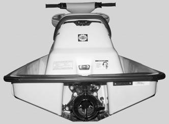
19)Air Intake Opening
This is where air enters to supply the engine and to ventilate the engine compartment. If the air intake opening is kept under water, water will get inside bilge. CAUTION: If the air intake opening is kept under water, such as turning constantly in tight circles, water will get inside bilge, which may cause severe damage to internal parts of the engine.
20)Seat Strap
The seat strap provides a handhold to assist boarding and is used as a handhold for the passenger.
21)Seat Latch
Removing the seat allows access to the engine compartment. The seat latch is located at the rear end and underneath the seat.
2-Up Seat Models
TYPICAL 1. Seat latch
3-Up Seat Models

1. Seat latch
All Models
To remove seat, pull the latch lever upward and hold. Lift and pull the seat rearward. NOTE:On the 3-up seat models, it is necessary to remove the seat extension first and repeat the same procedure to remove the seat.
Engine Compartment
This is where the mechanical, electrical and fuel/oil systems are located.
Some Models
When reinstalling the seat, insert seat front tab into body hook.
WARNING
Components inside engine compartment may be hot. When starting or operating the engine, do not touch any electrical part. Never leave any object, rag, tool, etc., in the engine compartment or in the bilge.

1. Insert this tab in hook 2. Hook
Some Models
When reinstalling the seat, insert seat hook into body front tab for each portion of the seat.

1. Insert this tab in hook 2. Hook
Some Models
When reinstalling the seat, place seat cavity over body hook.

1. Seat cavity

1. Body hook
All Models
To latch seat, align latch hole with pin then, firmly push downward on rear of the seat.

1. Latch hole 2. Pin
22)Seat Extension Latch (if so equipped)
Removing the seat extension allows access to the rear storage basket. It also gives access to the seat latch on models with a seat extension.

1. Seat extension latch 2. Rear grab handle Provides a handhold for boarding when needed and a handhold for the passenger or the spotter on 3-up seat models. See illustration above. CAUTION: Never use the grab handle to tow anything or to lift the watercraft.
24)Rear Storage Basket (if so equipped)
A convenient watertight, removable basket to carry personal articles.
TYPICAL
GTX DI Models
Spare Spark Plug Holder The storage basket features a spare spark plug holder. To keep spare spark plugs dry and prevent shocks that might affect the adjustment or break them, a holder is provided. Unscrew cap counterclockwise to expose the holder and insert spark plug in their holes. Reinstall cap.

1. Storage basket 2. Spare spark plug holder cap 3. Spark plug holder
NOTE: Adjust spare spark plug gap according to SPECIFICATIONS before installation. NOTE: Spare spark plugs are not supplied with the watercraft.
All Models 25)Bow and Stern Eyelets
Bow Eyelet Eyelets can be used for mooring, towing and as a tie-down point during trailering.

1. Bow eyelet Stern Eyelet
Some Models
This eyelet allows a rope with a hook, a closed end or an open end to be attached.

1. Stern eyelet
26)Mooring Cleats
All Models
These cleats can be temporarily used for docking, while refueling for example. CAUTION: Never use mooring cleats to pull or lift the watercraft.

1. Mooring cleats
27)Footboard
User’s feet should rest on the footboard when riding.
Provide a cushioned surface for the knees when boarding from rear of watercraft.
All Models 29)Boarding Platform
Provides a large surface for easier boarding from rear of watercraft.
30)Boarding Step (if so equipped)
A convenient step to help reboarding the watercraft.

1. Boarding step
Pull down the step with your hand and hold until a foot is put on the step.
31)Cooling System Bleed
Outlet

All Models

TYPICAL 1. Bleed outlet
When engine is running, water should flow from the outlet. This allows air in engine cooling system to escape. It also indicates that water is circulating in the cooling system. NOTE: It may be required to increase slightly the engine RPM to see the water flowing out. CAUTION: Should water not flow from outlet a few seconds after engine starts, immediately stop engine and refer to POST-OPERATION CARE and look for COOLING SYSTEM FLUSHING or refer to an authorized SEA-DOO dealer for servicing.
32)Flushing Connector (if so equipped)
A convenient connector is provided to allow easy installation of a garden hose to flush the cooling system.

TYPICAL
Refer to POST-OPERATION CARE section for proper use.
33)Bilge Drain Plugs
Should water be found in the bilge, it can be easily drained by unscrewing the drain plugs when engine is off and watercraft is out of water. CAUTION: Remove boat from water prior to unscrewing drain plugs.
TYPICAL 1. Drain plugs 2. Tighten 3. Unscrew
Tilt the watercraft slightly to the rear so that the water can completely flow out of the bilge. It is suggested to drain bilge on a ramp. CAUTION: Make sure drain plugs are properly secured prior to launching the watercraft in water.
34)Jet Pump Nozzle
Jet pump nozzle turns side to side via rider input at the handlebar. This provides directional control when engine is running.

TYPICAL 1. Jet pump nozzle
When selecting the neutral or reverse position with the shift lever, the reverse gate moves up or down to obtain the desired position.
TYPICAL 1. Reverse gate
36)Jet Pump Water Intake
The water is drawn up by the impeller through this opening. The water intake grate minimizes the entry of foreign objects into the propulsion system. WARNING
Keep away from intake grate while engine is on. Items such as long hair, loose clothing or personal flotation device straps can become entangled in moving parts resulting in severe injury or drowning.
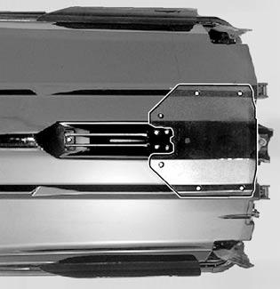
1. Water intake 2. Ride plate
37)Fuses
Fuses are located under seat in bilge. Refer to MAINTENANCE for more details.
38)Battery
Battery is located inside engine compartment. Refer to SPECIAL PROCEDURES.
39)Side Vanes (if so equipped)
Side vanes are part of Off-Power Assisted Steering (O.P.A.S.) system. When engine RPM is reduced, the side vanes are lowered to assist the steering system.
WARNING
Check handlebar and corresponding side vanes operation before starting. Never use side vanes as a supporting point to board the watercraft or to lift it. Never turn handlebar while someone is nearby rear of watercraft. Keep away from steering moving parts (nozzle, side vanes, linkage etc.).