13 minute read
MAINTENANCE

from 2003 Seadoo GTI GTI California GTI LE GTI LE RFI RX DI GTX DI Operator’s Guide Manual – PDF DOWNLOAD

Maintenance, replacement, or repair of the emission control devices and systems may be performed by any marine SI (spark ignition) engine repair establishments or individual.
Engine Emissions Information
Manufacturer’s Responsibility
Beginning with 1999 model year engines, PWC manufacturers of marine engines must determine the exhaust emission levels for each engine horsepower family and certify these engines with the United States of America Environmental Protection Agency (EPA). An emissions control information label, showing emission levels and engine specifications, must be placed on each vehicle at the time of manufacture.
Dealer’s Responsibility
When performing service on all 1999 and more recent SEA-DOO watercrafts that carry an emissions control information label, adjustments must be kept within published factory specifications. Replacement or repair of any emission related component must be executed in a manner that maintains emission levels within the prescribed certification standards. Dealers are not to modify the engine in any manner that would alter the horsepower or allow emission levels to exceed their predetermined factory specifications. Exceptions include manufacturer’ s prescribed changes, such as altitude adjustments for example.
Owner Responsibility
The owner/operator is required to have engine maintenance performed to maintain emission levels within prescribed certification standards. The owner/operator is not to, and should not allow anyone to modify the engine in any manner that would alter the horsepower or allow emissions levels to exceed their predetermined factory specifications.
EPA Emission Regulations
All new 1999 and more recent SEA-DOO watercraft manufactured by Bombardier are certified to the EPA as conforming to the requirements of the regulations for the control of air pollution from new watercraft engines. This certification is contingent on certain adjustments being set to factory standards. For this reason, the factory procedure for servicing the product must be strictly followed and, whenever practicable, returned to the original intent of the design. The responsibilities listed above are general and in no way a complete listing of the rules and regulations pertaining to the EPA requirements on exhaust emissions for marine products. For more detailed information on this subject, you may contact the following locations: VIA U.S. POSTAL SERVICE: Office of Mobile Sources Engine Programs and Compliance Division Engine Compliance Programs Group (6403J) 401 M St. NW Washington, DC 20460 VIA EXPRESS or COURIER MAIL: Office of Mobile Sources Engine Programs and Compliance Division Engine Compliance Programs Group (6403J) 501 3rd St. NW Washington, DC 20001 EPA INTERNET WEB SITE: www.epa.gov
WARNING
Only perform procedures as detailed in this guide. It is recommended that the assistance of an authorized SEA-DOO dealer be periodically obtained on other components/systems not covered in this guide. Unless otherwise specified, engine must not be running and the safety lanyard must be removed from its post for all maintenance procedures. Components inside engine compartment may be hot. Never use jet pump components or side vanes to lift the watercraft.
Lubrication
Use SEA-DOO synthetic grease or equivalent and lubricate PTO flywheel. Proceed as follows: Remove seat to expose engine compartment. Remove vent tube support (if so equipped).
PTO Flywheel
Remove the fasteners and pull out PTO flywheel guard.
GTI, GTI LE AND GTI LE RFI MODELS 1. Flywheel guard 2. Wing nuts TYPICAL — OTHER MODELS 1. Flywheel guard 2. Fasteners
Using a grease gun, carefully lubricate PTO flywheel at grease fitting until PTO flywheel boot begins to expand. CAUTION: Immediately stop lubricating as soon as PTO flywheel boot begins to expand to prevent damage or slipping.
1. PTO flywheel 2. Grease fitting 3. PTO flywheel boot
Reinstall and secure PTO flywheel guard.
Anticorrosion Protection
Throttle/Choke Cables Lubricate the throttle and choke cables (if so equipped) with BOMBARDIER LUBE lubricant or equivalent. Electrical Connections As necessary, apply anticorrosion product such as dielectric grease on battery posts and all exposed cable connectors.
CAUTION: Do not lubricate connectors of the Multi-Purpose Electronic Module. Additional Lubrication BOMBARDIER LUBE lubricant or equivalent will help prevent corrosion of metallic parts and maintain proper operation of moving mechanisms. WARNING
Do not lubricate the safety lanyard post.
Carburetor-Equipped Models
Choke Lever Fully pull choke lever and lubricate the metallic portion.
All Models
Seat Opening Mechanism, Tab, Hook and Lock Pin
TYPICAL 1. Front tab 2. Rear mechanism TYPICAL
Carburetor/Throttle Body and Oil Injection Pump Lubricate springs, shafts and exposed portion of cables. Reverse Gate Lubricate pivoting points and mechanism.
Periodic Inspection
Routine maintenance is necessary for all mechanized products. A periodic inspection contributes to the product’ s life span. The following maintenance chart gives guidelines for regular watercraft servicing scheduled to be performed by you and/or by an authorized SEA-DOO dealer. The schedule should be adjusted according to operating conditions and use. IMPORTANT: Schedule for watercraft rental operations or higher number of hour use, will require greater frequency of inspection and maintenance.
GENERAL
ENGINE
COOLING SYSTEM
FUEL SYSTEM
LUBRICATION SYSTEM DESCRIPTION FREQUENCY
I: Inspect, verify, clean, adjust, lubricate, replace if necessary C: Clean L: Lubricate R: Replace FIRST 10 HOURS EVERY 25 HOURS OR 3 MONTHS EVERY 50 HOURS OR 6 MONTHS EVERY 100 HOURS OR 1 YEAR TO BE PERFORMED BY
Lubrication/corrosion protection ➀ C C
Support and rubber mount I I D Exhaust system fasteners ➄ I I D RAVE valve (if so equipped) ➄ C C D Top end (leak test, piston and ring clearance) (DI models only) ➄ ➈ D Counterbalance shaft oil level (if so equipped) I I D Spark plug ➃ I R D Ignition timing (all models except DI) ➄ I D TDC setting (DI models only) ➄ ➈ D Flushing ➂ C C Hose condition and fasteners I I D Engine drain tubes ➀ I C Water flow regulator valve (if so equipped) I D Carburetor including choke/throttle cable (carburetor-equipped models) I I D
Throttle/choke cables (carburetor-equipped models) ➀ I C Fuel filter (except RFI models) and lines I I D Fuel filter (except DI and RFI models) R D Fuel filter (DI models only) ➇ D Oil leakage between cylinder head and injector (DI models) ➄ I I D Fuel injection system sensors (except throttle body), (RFI and DI models) ➄ I I D Throttle body and their sensors (DI models) ➄ ➅ I I D Fuel vent line pressure relief valve I D Fuel lines, connections (DI models fuel system pressurization ➄ ), check-valve and I I D Carburetors/throttle bodies, sensors, fuel lines, fuel rail and fittings (if so equipped) ➄ I I D Air intake silencer fit/tightness I I D Fuel tank straps I I C Oil injection pump ➄ I I D
Oil filter and lines I I D
Oil filter R D
Oil reservoir straps I C
ELECTRICAL SYSTEM
STEERING SYSTEM
O.P.A.S. SYSTEM
PROPULSION SYSTEM
HULL AND BODY
I: Inspect, verify, clean, adjust, lubricate, replace if necessary C: Clean L: Lubricate R: Replace FIRST 10 HOURS EVERY 25 HOURS OR 3 MONTHS EVERY 50 HOURS OR 6 MONTHS EVERY 100 HOURS OR 1 YEAR TO BE PERFORMED BY
Electrical connections condition and fastening (ignition system, electrical box(es), starting system, fuel injectors (RFI and DI models), etc.) I I D
MPEM mounting brackets/fasteners I D Digitally Encoded Security System I I D Monitoring beeper I I D Battery condition and strap(s)/fasteners I I D
Steering cable I I D
O.P.A.S. system I I D
Drive shaft boot and spline condition (if so equipped) I ➁ D Drive shaft protection hose I ➁ D PTO flywheel L L C Shifter system/cable I I D VTS (Variable Trim System) (if so equipped) I I D Jet pump reservoir oil level/oil condition R I R D Jet pump cover pusher (if so equipped) I D Impeller shaft seal ➆ D Impeller condition and impeller/wear ring clearance R ➁ D Water intake grate condition I ➁ C
Bailer pick-ups, check for obstructions I I C
Hull condition I I C
NOTE: Some items are included in the PRE-OPERATION CHECKS and not necessarily repeated in this chart. D:Dealer C:Customer ➀ Every 10 hours in salt water use. ➁ These items have to be initially checked after 25 hours. Thereafter, servicing to be made as specified in this chart. ➂ Daily flushing in salt water or foul water use. ➃ Except DI models. ➄ Emission-related component. ➅ In salt water use. ➆ Replace at 150 hours. ➇ Replace at 250 hours. ➈ Check at 350 hours or 5 years. 78
Throttle and Choke Cable Inspection
Throttle Cable
Depress and release the throttle lever. It should operate smoothly and return to its initial position without any hesitation. Refer to an authorized SEA-DOO dealer if necessary.
Carburetor-Equipped Models
Do not activate throttle lever unnecessarily, when engine is not running. Carburetors are equipped with fuel accelerator pumps. These pumps deliver fuel to the engine each time throttle lever is depressed.
All Models
WARNING
Do not alter or tamper with throttle cable adjustment or routing.
WARNING
If throttle lever does not automatically return, do not operate watercraft and see your authorized SEA-DOO dealer.
F01K01Y
1. Should move freely 1
Carburetor-Equipped Models Choke Cable
Ensure choke cable operates smoothly and without any hesitation from fully opened to fully closed. When the choke lever is fully pulled, choke should be fully applied. Refer to an authorized SEA-DOO dealer if necessary. Carburetor adjustment is very important to allow good engine operation and therefore watercraft performance. Carburetor adjustment requires technical knowledge and experience to have the correct mixture supplied to the engine. CAUTION: Serious engine damage can occur with improper carburetor adjustment.
GTI California Models
There is no mixture adjustment to be performed by the dealer. IMPORTANT: Trying to bypass the anti-tamper screws could damage the carburetor. It could also change the engine emission level and lead the engine not to meet the California emission control regulations.
Fuel Injection System
RFI and DI Models
The fuel injection system inspection should be performed by an authorized SEA-DOO dealer. CAUTION: Never use injector cleaning products. They may contain additives that could damage injector components.
All Models Fuel and Oil Filters
The fuel filter and the oil filter should be replaced by an authorized SEA-DOO dealer. Fuel system pressurization should be conducted at the same time. CAUTION: An obstructed oil filter will cause oil starvation resulting in serious engine damage.
When the handlebar is directed in straight ahead position, the jet pump nozzle should be in the same direction allowing the watercraft to run in a straight line. The rear edge of side vanes (if so equipped) should be pointing out side by approximately 20° when the handlebar is pointing straight ahead. Refer to an authorized SEA-DOO dealer if an adjustment is necessary. WARNING
Ensure the handlebar and jet pump nozzle operate freely from side to side and are not stressing the steering cable or brackets. Never turn handlebar while someone is nearby rear of watercraft. Keep away from steering moving parts (nozzle, side vanes, linkage etc.).
VTS Adjustment (if so equipped)
Push on arrow pointing upward on VTS button until the VTS stops. The nozzle should be up without interfering with the venturi.
TYPICAL 1. Push on arrow pointing upward on VTS button 2. No interference 3. Nozzle up
Push on arrow pointing downward on VTS button until VTS stops. The nozzle must be down and it must not interfere with the venturi.
1. Push on arrow pointing downward on VTS button 2. No interference 3. Nozzle down
If VTS needs to be readjusted, refer to an authorized SEA-DOO dealer. CAUTION: Trim ring and/or nozzle should not interfere at any position.
Vacuum Bailer Pick-Ups
They are located each side of the drive shaft tunnel. Two pick-ups use a low pressure area in the jet pump to siphon the water out of the bilge when the engine is operating. Inspect each pick-up screen for obstructions, clean as necessary.

TYPICAL 1. Vacuum bailer pick-ups
If an electrical problem occurs, check the fuses. If a fuse is burnt, replace by one of the same rating. Follow procedures below. WARNING
Do not use a higher rated fuse as this can cause severe damage. If a fuse has burnt out, source of malfunction should be determined and corrected before restarting. See an authorized SEA-DOO dealer for servicing.
Fuses can be found on the MPEM. There are other fuses in the rear electrical box on all models except RFI.
MPEM
To access fuses on the MPEM, remove seat.
GTI, GTI LE Models
Locate MPEM besides engine.

TYPICAL 1. MPEM
Fuses are identified, look besides the fuse holder. SPR means spare (fuse).
FUSE IDENTIFICATION 5 A: MPEM 15 A: Battery
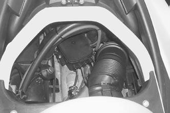
GTI LE RFI Models
Locate MPEM in front of engine.

1. Engine 2. MPEM 3. Main fuse 4. Charging system fuse


1. Battery 2. MPEM 3. Fuel pump
SPR means spare (fuse).
RX DI Models
To access fuses on the MPEM, open front storage compartment cover and remove storage basket. Locate MPEM on the left side of watercraft.
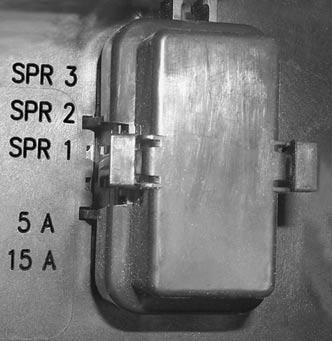
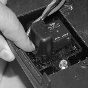
GTX DI Models
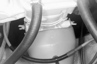
Locate MPEM besides engine.

TYPICAL 1. MPEM 2. Fuses location Fuses are identified, look above and besides the fuse holder.
FUSE IDENTIFICATION 1. Fuse identification 2. Fuse description
Fuse identification: The fuses (F) are identified from 1 to 6. Fuse description: The fuses are described with abbreviation as follows: FP: Fuel pump ACC: Accessories (information center) REG: Regulator (charging system) VTS: Variable Trim System. Fuse is installed but not in use BAT: Battery INJ: Injection system The fuse description is followed by the ampere rating (A).
All Models
Remove fuse cover from the MPEM.

TYPICAL 1. MPEM 2. Fuse cover
Use the tabs of the fuse cover to remove and reinstall fuses.

1. Fuse cover 2. Fuse tabs
Rear Electrical Box
Remove seat.
GTI, GTI LE and RX DI Models
Remove darts retaining tubes then pull out both vent tubes each side of electrical box at rear of hull.

TYPICAL 1. Rear electrical box 2. Remove vent tubes
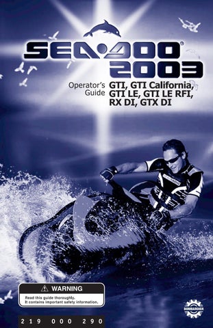
GTX DI Models
Locate electrical box at the back of the bilge.
1. Electrical box
Some Models
Unclip and remove cover of the electrical box to expose the holder of the main fuse.

TYPICAL 1. Fuse holder
Properly reinstall removed components.
Some Models
Unclip and remove cover of the electrical box.


TYPICAL 1. Fuse holder
All Models
Properly reinstall removed components.
O.P.A.S. System (if so equipped)
The O.P.A.S. system operation and condition should be checked by an authorized SEA-DOO dealer.
General Inspection and Cleaning
Inspection
Check engine compartment for any damage and fuel/oil injection systems for leaks. Ensure all hose clamps are properly secured and no hose is cracked, kinked or presenting any other damage.
Inspect muffler, battery, fuel tank and oil reservoir fastening devices. Visually check electrical connections for corrosion and tightness.
WARNING
If any gasoline leak and/or odor are present, do not start the engine. Have the watercraft serviced by an authorized SEA-DOO dealer.
Inspect hull and jet pump water intake grate for damage. Replace or have damaged parts repaired. WARNING
Periodically verify the seat lock pin and tighten if needed. Make sure seat securely latches.
Cleaning
The bilge should be cleaned by an authorized SEA-DOO dealer to remove any fuel/oil/electrolyte deposits and mildew. Occasionally, wash the body with water and soap (only use mild detergent). Remove any marine organisms from engine and/or hull. Apply non-abrasive wax such as silicone wax. CAUTION: Never clean fiberglass and plastic parts with strong detergent, degreasing agent, paint thinner, acetone, etc. Stains may be removed from seat and fiberglass with Knight’s Spray-Nine from Korkay System Ltd or the equivalent. Respect the environment by ensuring fuel, oil or cleaning solutions do not drain into the waterways.