8A - 12
BATTERY/STARTING/CHARGING SYSTEMS DIAGNOSTICS
hold the ignition switch in the START position. Observe the voltmeter. If voltage is detected, correct poor contact between cable clamp and post. (b) Connect positive lead of the voltmeter to the positive battery post, and negative lead to the positive battery cable clamp. Rotate and hold the ignition switch key in the START position. Observe the voltmeter. If voltage is detected, correct poor contact between the cable clamp and post. (c) Connect negative lead of voltmeter to negative battery terminal, and positive lead to engine block near the battery cable attaching point (Fig. 10). Rotate and hold the ignition switch in the START position. If voltage reads above 0.2 volt, correct poor contact at ground cable attaching point. If voltage reading is still above 0.2 volt after correcting poor contacts, replace ground cable.
Ä
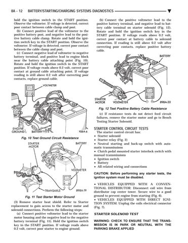
(b) Connect the positive voltmeter lead to the positive battery terminal, and negative lead to battery cable terminal on starter solenoid (Fig. 12). Rotate and hold the ignition switch key in the START position. If voltage reads above 0.2 volt, correct poor contact at battery cable to solenoid connection. If reading is still above 0.2 volt after correcting poor contacts, replace positive battery cable.
Fig. 12 Test Positive Battery Cable Resistance (c) If resistance tests do not detect feed circuit failures, remove the starter motor and go to Bench Testing Starter Solenoid.
STARTER CONTROL CIRCUIT TESTS Fig. 10 Test Ground Circuit Resistance
The starter control circuit has: • Starter solenoid • Starter relay (Fig. 2) • Neutral starting and back-up switch with automatic transmissions • Clutch pedal mounted starter interlock switch with manual transmissions • Ignition switch • Battery • All related wiring and connections CAUTION: Before performing any starter tests, the ignition system must be disabled.
Fig. 11 Test Starter Motor Ground (3) Remove starter heat shield. Refer to Starter replacement to gain access to the starter motor and solenoid connections. Perform the following steps: (a) Connect positive voltmeter lead to the starter motor housing and the negative lead to the negative battery terminal (Fig. 11). Hold the ignition switch key in the START position. If voltage reads above 0.2 volt, correct poor starter to engine ground.
• VEHICLES EQUIPPED WITH A CONVENTIONAL DISTRIBUTOR: Disconnect coil wire from distributor cap center tower. Secure wire to a good ground to prevent engine from starting (Fig. 6). • VEHICLES EQUIPPED WITH DIRECT IGNITION SYSTEM: Unplug the coils electrical connector (Fig. 7).
STARTER SOLENOID TEST WARNING: CHECK TO ENSURE THAT THE TRANSMISSION IS IN PARK OR NEUTRAL WITH THE PARKING BRAKE APPLIED