Fuses Engine compartment 11B/13-15
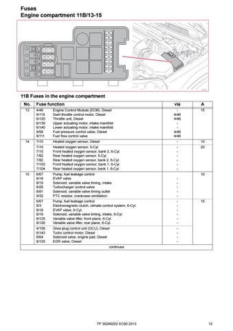
11B Fuses in the engine compartment No.
Fuse function
via
A
13
4/46 6/118 6/120 6/139 6/140 8/98 8/111
Engine Control Module (ECM), Diesel Swirl throttle control motor, Diesel Throttle unit, Diesel Upper actuating motor, intake manifold Lower actuating motor, intake manifold Fuel pressure control valve, Diesel Fuel flow control valve
4/46 4/46 4/46 4/46
15
14
7/15
Heated oxygen sensor, Diesel
-
10
7/15 7/15 7/82 7/82 7/103 7/104
Heated oxygen sensor, 5-Cyl. Front heated oxygen sensor, bank 2, 6-Cyl. Rear heated oxygen sensor, 5-Cyl. Rear heated oxygen sensor, bank 2, 6-Cyl. Front heated oxygen sensor, bank 1, 6-Cyl. Rear heated oxygen sensor, bank 1, 6-Cyl.
-
20
6/67 8/18 8/19 8/28 8/81 9/32
Pump, fuel leakage control EVAP valve Solenoid, variable valve timing, intake Turbocharger control valve Solenoid, variable valve timing outlet PTC resistor, crankcase ventilation
-
6/67 8/3 8/18 8/19 8/125 8/126
Pump, fuel leakage control Electromagnetic clutch, climate control system, 6-Cyl. EVAP valve, 6-Cyl. Solenoid, variable valve timing, intake, 6-Cyl. Variable valve lifter, front plane, 6-Cyl. Variable valve lifter, rear plane, 6-Cyl.
-
4/109 6/143 8/64 8/120
Glow plug control unit (GCU), Diesel Turbo control motor, Diesel Solenoid valve, engine pad, Diesel EGR valve, Diesel
-
15
10
15
continues
TP 39249202 XC90 2013
12
