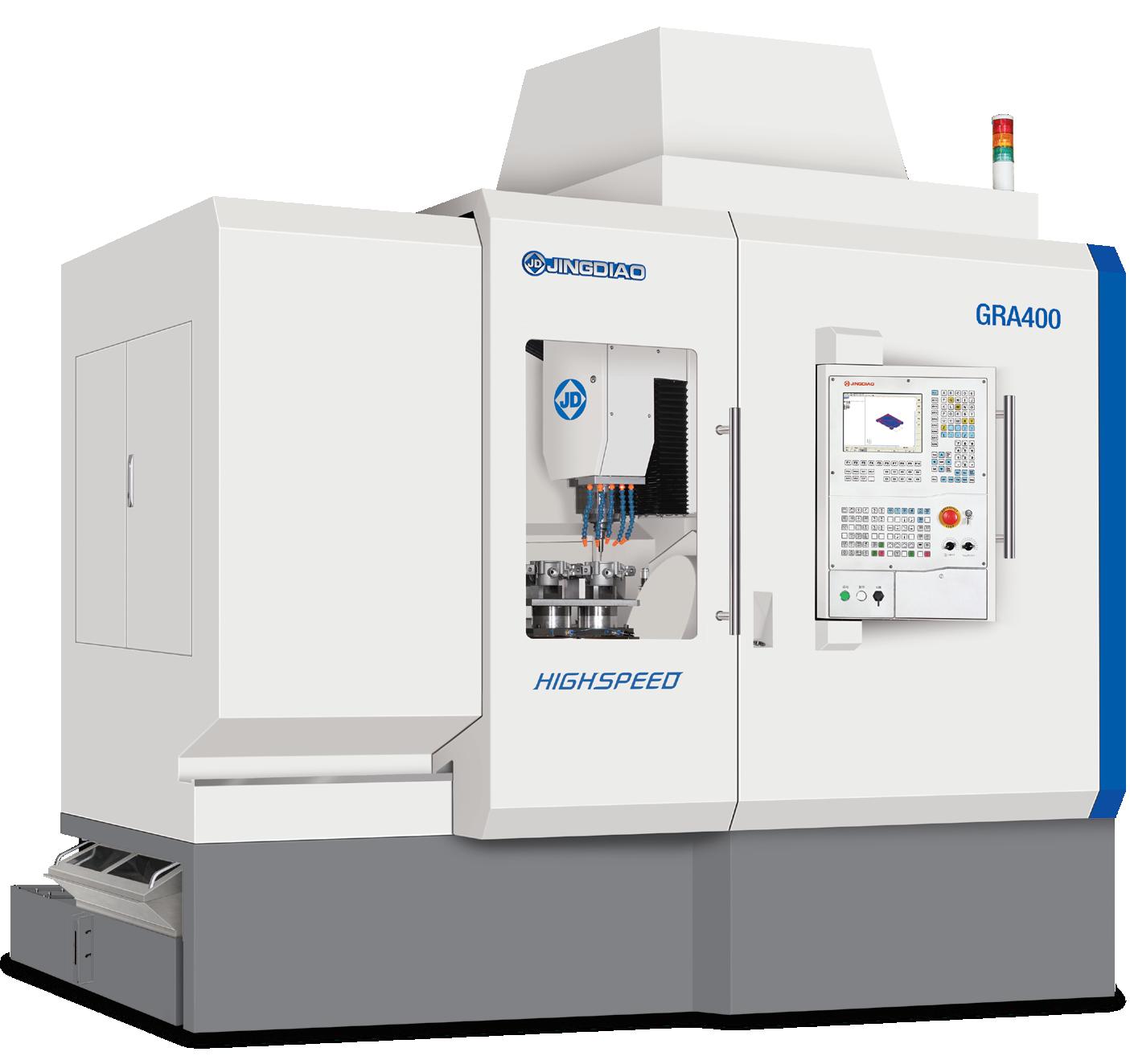
GRA400
5-Axis high-speed machining center designed for the precision machin ing of dies, molds and complex hard ware parts.
 JINGDIAO 5-AXIS HIGH-SPEED MACHINING CENTER

5-Axis high-speed machining center designed for the precision machin ing of dies, molds and complex hard ware parts.
JINGDIAO 5-AXIS HIGH-SPEED MACHINING CENTER
With fully closed-loop control technology, the GRA400 is suitable for 5-axis machining of precision mold,precisionpartsandcomplexhardwareparts.


01
Max. Workpiece Dimension Z-axis


02
The operator loads the workpiece through the front door of the machine, and the chip conveyor is completed by the in-machine spiral chip conveyor rod.

In order to facilitate the operation of the machine, the structural design of each operation part conforms to the ergonomics.
The machining effect of "0.1 μm feed, 1 μm cutting, nano surface finish" can be achieved stably.

The machines are capable of milling, grinding, drilling, boring, tap-ping, and other composite processing, and side milling .


04
The direct drive double axis rotary table has a strong load capacity with high machining accuracy.


03 Using the cooling technology of rotary table, bearing and screw nut and the fully enclosed shield improve the thermal stability of machine tool effectively.
Max. load (kg/lb): 150/330.7
Full closed loop control, motion axes equipped with linear glass scales.
Inverted “L” structure.
Travel (X/Y/Z) mm/ (in) 450/680/400 (17.7/26.8/15.7)

A/C Rotation Angle (deg) -120~90/360
All round cooling design, using rotary table cooling, bearing cooling, screw cooling technology, and equipped with fully enclosed machine covers.

The worktable is close to the operator, which makes it easy to load and unload the workpiece.

Pneumatic components and lubricating components are all installed on the right side of the machine, which is convenient for inspection and maintenance.
The tool magazine door has a large opening degree, which is convenient for the loading and unloading of tools.
Classical fixed beam gantry structure.
Composite Machining Test Piece
200×150×150 /7.9×5.9×5.9
Highlights:


Realize milling, drilling, tapping, reaming, boring and other composite processing with one clamping


JINGDIAO's high speed spindles are the machine's main power source which produce precision machining results. Our in-house built spindles have low vibration, and high thermal stability resulting in a small coefficient of thermal expansion and stable cutting in conditions.
Optional
JD150SC-20-HA50 (Coolant Through Spindle)
Speed: 20,000 rpm
Tool Holder: HSK-A50
Basic Specification
Clamping Diameter (mm/in):
Φ150/Φ5.9 (0, -0.009) mm
Output Power (S6-60%): 18 KW
Output Torque (S6-60%): 21.5 Nm
Speed: 20,000 rpm
Tool Holder: HSK-A50
Mold Insert of Auto Engine Cylinder
Size (mm/in):
Material:
Highlights:
183×184×191 /7.2×7.2×7.5
H13 (HRC52)
The virtual processing technology of JINGDIAO
CAM software completes the optimization of the tools’ clamping length and machining angle; Cornering of the side wall with R0.75 mm ball end mill.
Throttle Die Casting


Size (mm/in):
Material:
Highlights:
135×115×75 /5.3×4.5×3.0
ADC12 (HB90) 12% Silicon
The coaxiality of the hole is less than 0.01 mm, and the roughness of the reaming hole is less than 0.2 μm;
JINGDIAO on-machine measurement technology achieves continuous and stable mass production, and the yield of the part is increased from 70% to 98%.

Clamping Diameter (mm/in): Φ150/Φ5.9 (0, -0.009) mm
Output Power (S6-60%): 18 KW
Output Torque (S6-60%): 21.5 Nm
Speed: 20,000 rpm
Tool Holder: HSK-A50
Weight (kg/lb): 46.5/102.5
Taper Bore Radial Runout ≤1.5 μm (5.9×10⁻⁵ in)
Rotor End Face Axial Runout ≤1 μm (3.9×10⁻⁵ in)
Vibration at Maximum Speed ≤0.6 mm/s (1.44 ipm)
Weight (kg/lb): 46.5/102.5
JD130EF-32-HE32
Speed: 32,000 rpm
Tool Holder: HSK-E32
When machining with coolant through spindle, the cutting fluid or cutting oil is ejected to the tool tip through the hole of the internal cooling tool. This can improve the cooling and lubricating effects on the tool and workpiece. Coolant thrugh spindle is hepful in deep hole drilling since the chips are quickly discharged through the spiral groove of the drill. This greatly improves the machining efficiency and tool durability.

JD130SC-24-HA40
Speed: 24,000 rpm
Tool Holder: HSK-A40
JD130SCG-24-HA40
Speed: 24,000 rpm
Tool Holder: HSK-A40
JD130S-24-BT30
Speed: 24,000 rpm
Tool Holder: BT30
JD150SCG-20-HA50
Speed: 20,000 rpm
Tool Holder: HSK-A50
Different machining conditions have different machining data, which is only for reference.
The JD50 CNC system is developed independently by JINGDIAO. The control is highly efficient, reliable and very precise. Additionally, it has rich programming functions, convenient operation, flexible peripheral control, and can meet the processing Requirements of high machining accuracy and fine surface finishing.


The programming resolution and control resolution are 0.1 μm (3.9×10 -6 in).


Supports linear, plane arc, space arc, spiral line, spline and involute interpolation methods. Support pitch compensation and reverse clearance compensation. Support RTCP multi-axis motion control.


Various programming methods and flexible technical process design. Abundant types of interfaces and buses, with strong peripheral expansion capabilities.

Unique external extended function instructions (G100), which can realize instruction-level peripheral control, human-computer interaction, and complex data operations.
Includes on-machine contact and non-contact measurement functions, which results in high-precision 2D and 3D measurements. Built-In CAM technology and intelligent modification technology supports the on-machine tool-path deformation compensation machining.


Incorporates multiple communication protocols and remote monitoring.


Tool center point control function.


To meet your production needs, we have a variety of tool magazines to choose from.
Assures high-precision multi-axis machining.


Features
Direct drive motor, with emergency braking function. Bridge deck tailstock structure, high precision and stable operation. Circulating water cooling technology reduces the thermal deformation. Five-Axis simultaneous processing, multi surface positioning processing. The hollow design in the shaft makes the pipeline layout more convenient.


MHS150 material handling system is mainly composed of handling manipulator, storage module and control system. It is equipped with tridimensional fixed plate exchange system, which can realize the automatic handling of workpiece under the condition of no human intervention.


When equipped with MHS150 material handling system, the GRA400 can achieve continuous and stable unattended production.
We can design and develop the structure according to your actual production needs.
The exceptional features of JINDAIO operation management system makes it easier to collaborate with colleagues within in your manufacturing team. The personnel will perform Their respective duties, guarantee the continuous operation of the system, and improve the machines' actual utilization rate.
The scraper style chip conveyor collects and filters out the collection of cutting chips from the machining fluid.

Improves maintenance by moving the chips into disposal container. Cutting fluid service life is extended by using a multistage filtration unit. Equipped with a cleaning mechanism and drop recovery mechanism which is self cleaning resulting cutting fluid recovery.


Appropriate Chip Types
MQL cooling technology is used in precision grinding and micro milling. Equipped with MQL, the temperature fluctuation in the machine can be controlled within 0.5 °C (32.9 °F).


Scraper Type Chip Conveyor


Filtering Tank Chip Collector
The oil mist collector reduces the rise of internal temperature caused by the oil mist accumulation. It eliminates the diffusion of oil mist, reduces the internal electrical fault of the machine tool, improves the stability of equipment operation, reduces air pollution, and protects the workshop environment.

Tool holders require good clamping performance such as high clamping accuracy, low vibration and the ability minimize oil mist during high-speed machining.
JINGDIAO tool holders have anticorrosive properties, minimize air resistance, and are designed good dynamic balance. Our tool holders are available in various styled including BT30, HSK.

JINGDIAO's innovative on-machine measurement and intelligent modification technology (omim) is an ideal solution that integrates CAM programming technology, numerical control processing and precision inspection technology. Its intelligent application can effectively shorten the production cycle of the workpiece, streamline the processing flow, and improve quality and efficiency for production and machining

This feature automatically corrects the workpiece deviation through inspecting the offset of workpiece on machine and adjusting the program in control system. This reduces workpiece setup time, improves machining quality and increases production.


The CAM function embedded in the CNC system can compensate the inaccurate machining path, which caused by workpiece deformation, clamping deformation and clamping deviation, achieve five-axis adaptive machining.


Machining and inspection are achieved on one machine, forming a new model of "integration of machining and inspection". The digitalization of CNC machining experience enables a entry-level operator to complete precision machining. The actual processing time proportion of CNC machines has increased from 25% -45% to 45% -70%

During the 5-axis machining process, JINGDIAO tool inspection system can inspect the errors of different positions of the tool contour of the bull nose tool, ball-end tool and other tools for precision machining and compensate intelligently. This can effectively reduce the unqualified workpiece accuracy caused by the tool inaccuracy.


With this feature, the remaining stock at each machining step can be measured in real time, and the inspection results will be displayed on the machine's control. The operator can analyze the results in order to ensure that an even amount of material is removed at every machining step. This results in reduced tool wear, constant chip load, improved machining accuracy and improved surface finishes.


With JINGDIAO's software, the actual production materials and process parameters are digitized to ensure the correct information is selected by the process personnel, material preparation personnel and the operator. This creates a seamless integration process development, material preparation and machine operation, and improves the accuracy and fluency of the machining Process.


Five-axis milling is a complex machining process. During the machining there is the risk of collisions between tools, tool holders and the workpiece. JINGDIAO uses its SurfMill software to establish the connection between production materials, CAM programming and actual processing in a virtual environment. The user can build the same digital scene in the software, simulate the machining process, analyze and adjust the process, and eliminate the machining risk in the software programming stage.


Technical Points Mirror the Actual Machining Environment to Ensure the Accuracy of Interference Risk Inspection


1 2 3
Risk Type
Cause Of Risk Solutions
Informatization of Production Materials to Avoid Risks Caused by Wrong Selection of Materials


The Macro Program Fool-Proof to Avoid Risk Caused by Mis-Operation by Personnel
With this software, the program processing, measurement, preparation and logical judgment are combined into one program. The operator only needs to press the start button to begin the processing of the part which reduces machine setup time.
Processing

Items Standard Value
Position Accuracy (X/Y/Z) mm/ (in) 0.002/0.002/0.002 (0.00008/0.00008/0.00008)
Position Accuracy (A/C) sec 8/8
Repeatability (X/Y/Z) mm/ (in) 0.0018/ 0.0018/ 0.0018 (0.00007/0.00007/0.00007)
Repeatability (A/C) sec 5/5
Travel (X/Y/Z) (mm/in) 450/680/400 (21.7/26.8/15.7)
A/C Rotation Angle deg -120~90/360
Table Diameter (mm/in) φ400/φ15.7
Max. Load (kg/lb) 150/330.8
Max. Spindle Speed (rpm) 32,000 (HSK-E32) 24,000 (BT30) 20,000 (HSK-A50)
Tool Magazine/Capacity 63 (Chain-Type Tool Magazine)
Rapid Speed (X/Y/Z) m/min (in/min) 15 (590.6)
Rapid Rotation Speed (A/C) rpm 60/100
Max. Cutting Feed Speed (X/Y/Z)
m/min (in/min) 10 (393.7)
Max. Cutting Feed Speed (A/C) rpm 60/100
Drive System AC Servo
Voltage 3-Phase, 480V/60Hz
Air Pressure (MPa) ≥0.55
Machine Weight (kg/lb) 10700/23593.5
Items Configuration
Tool Magazine
Items Configuration
Chain Type Tool Magazine with Manipulator (63 Tools) (HSK-A50)
Chain Type Tool Magazine with Manipulator (53 Tools) (HSK-A50)
Chain Type Tool Magazine with Manipulator (36 Tools)
Cooling System
Coolant Device (Half Ring Nozzle, 5 Nozzles)
Coolant Device (Ring Nozzle, 6 Nozzles)
Coolant Tank
Cutting Air Cooling System
Spindle Cooling
Rotary Table Cooling
Screw Cooling
Control Cabinet Cooling
Oil-Water Separating System
Oil-Mist Separation System

Micro Mist Lubrication
Chip Conveyor
Scraper Type Chip Conveyor
Internal Spiral Chip Conveyor
Chip Conveyor Interface
Chip Collection
Measurement System
Contact-Type Tool Set
Laser Tool Set
JINGDIAO On-Machine Measurement System
Standard Calibrating Ball
Others
MPG (Manual Pulse Generator)
Control System
JD50 CNC System
CAM Software
JDSoft SurfMill 8.0
Spindle
JD130EF-32-HE32
JD130S-24-BT30 (BT30)
JD130SC-24-HA40 (HSK-A40 Coolant through)
JD130SCG-24-HA40 (HSK-A40, Coolant through, Grinding)
JD150S-20-HA50/A (HSK-A50)
JD150SC-20-HA50 (HSK-A50, Coolant through)
JD150SCG-20-HA50 (HSK-A50, Coolant Through, Grinding)
Bag Type Filtration System
Hollow Filtration System
Front Door Safety Lock
Low Oil Pressure Inspection Device
Low Air Pressure Inspection Device
Ground Protector of Power Leakage
Machine Foot Alarm
Lubricating Oil Inspection
Auto Power off Function
Fax: (847) 906-8800
Email: usa@JINGDIAO.com
Website: us.JINGDIAO.com

US.JINGDIAO.COM
The pictures of the equipment are for your reference only. The configurations and parameters are subject to change without notice. The final interpretation of this brochure is owned by Beijing JINGDIAO Group Co., Ltd.
Print Date:2021.01