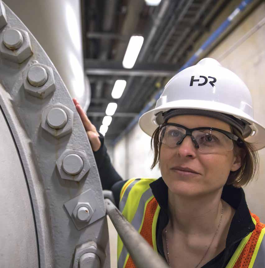
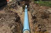
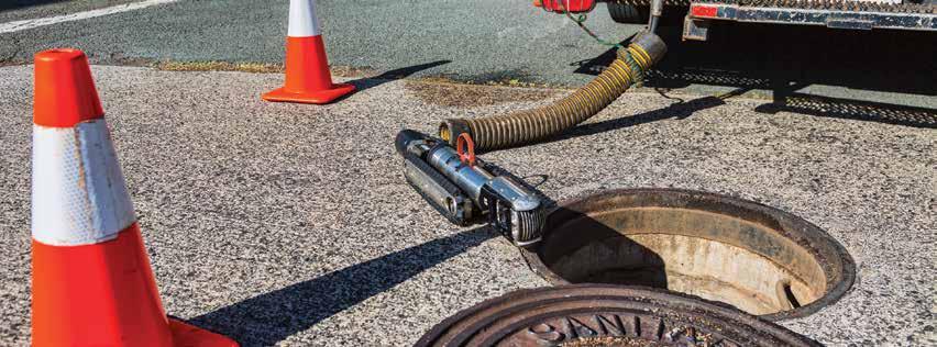
Infrastructure in the U.S. is in need of replacement and rehabilitation.
The American Society of Civil Engineers (ASCE) Infrastructure Report Card graded our pipelines a D or less. According to the U.S. Environmental Protection Agency (EPA), there are over 80,000 miles of public sewers and between 23,000 to 75,000 sanitary sewer overflows every year; in drinking water, over 240,000 water main breaks occur each year, wasting six billion gallons of treated water every day.
The EPA estimates $271 billion is needed for wastewater infrastructure over the next 25 years and the American Water Works Association (AWWA) estimates that upgrading existing water systems to meet the drinking water needs of a growing population will require at least $1 trillion.
Replacement is not the only option to address aging infrastructure.
There are several methods of pipeline rehabilitation methods. The chosen method will depend on the pipe design, size and material, available access, surrounding soils and whatever issue is prompting the work. Available rehabilitation and life extension methods can protect pipelines from corrosion, restore structural integrity, reduce infiltration, eliminate leaking joints, improve water quality and increase pipeline flow capacity.
For owners of storage and treatment facilities, balancing the rehabilitation required to maintain regulatory compliance and provide reliable and safe operations is an effort that calls for careful evaluation, planning and budgeting to meet today’s financial constraints. Condition assessments allow owners to integrate infrastructure improvements with regulatory compliance-driven projects. Condition assessments may also identify maintenance and operations adjustments that can extend facility life.
Pressure Pipes (Water Mains and Force Mains)
Choosing an Assessment Method
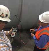
Assessing Corrosion Risk With Corrosivity Surveys
Selecting Condition Assessment Technologies for Pressure Pipes Based on Pipe Material
Condition Assessment Technologies and Tests for Pressure Pipes
Pipes (Storm and Sanitary Sewers)
Condition Assessment Technologies for Gravity Pipes
Pipelines
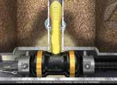
Pressure Pipes
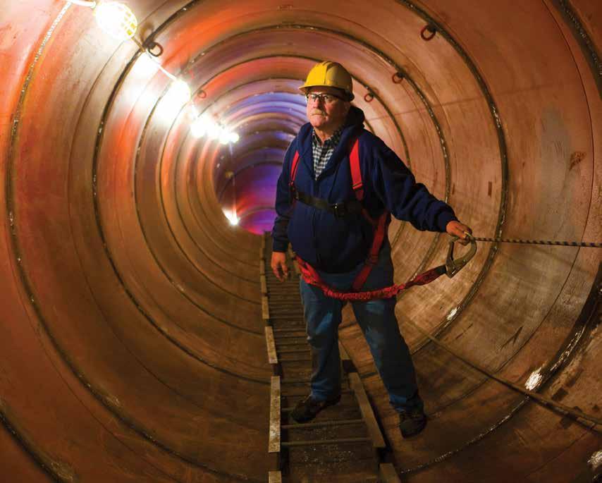
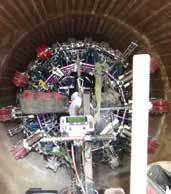
The pressure pipeline condition assessment industry has made major strides in methodologies and technologies. However, whether it is a sewer force main or a water transmission main, older pipeline designs seldom considered the need for access for inspection or
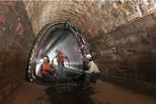
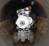
Gravity Pipes
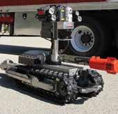
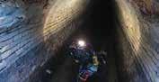
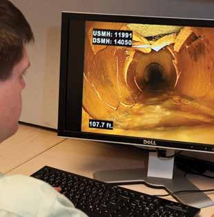
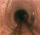
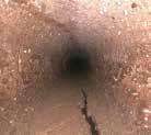
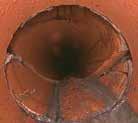
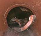
Current methods of gravity pipeline inspection use sophisticated and robust CCTV equipment with high-definition digital capabilities. Laser, sonar and additional sensors can be added to identify debris and measure vertical and horizontal deflections, hydrogen sulfide and many more parameters. On the low technology side, observations and debris from pipe cleaning have always been a primary source of condition assessment information for maintenance optimization and a secondary source for capacity and structural decisions. Federal and State regulations are in place for CSOs and SSOs in sanitary sewers.
assessment purposes. Removing a pipeline from service to assess its condition is a challenge and the costs associated with accessing the pipeline to employ new technologies can be daunting.
Storm sewers are probably the infrastructure asset most taken for granted. Yet, if they fail to perform, the resultant flooding can threaten public health and safety as well as cause significant property damage. Storm sewers have a greater opportunity to collect surface debris that can cause clogs, backups and failures. Since storm sewer construction methods and materials are similar to sanitary sewers, condition assessment methods also are also similar.
Assessment Process
The general progression for pipeline condition assessments are shown below. Using multiple methods to find all defects is necessary to provide a more complete understanding of pipe condition. However, some steps can be omitted and/or modified for each specific situation.
Risk assessment to determine which pipelines warrant the most attention
Desktop analysis of drawings, soils reports, break/repair history, operational conditions and staff interviews, to determine the general likelihood of a break
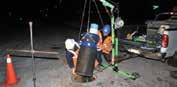
Site reconnaissance and inspection planning (accessibility, traffic, other utilities)
Indirect assessments, including: corrosivity survey and corrosion-activity measurements (close-interval survey)
Leak detection surveys (external or internal)
Low-resolution direct assessments: acoustic-velocity measurements of pipe stiffness and detection of stress anomalies through analysis of electromagnetic fields
Excavations/external exams where leaks, anomalies or corrosion hot spots are identified or suspected, including: highresolution scanning tools (ultrasonic, magnetic flux leakage, remote-field/ broadband electromagnetic), electrical measurements to detect corrosion, coating defects and bi-metallic couples
Internal physical-entry or robotic visual (CCTV) inspections, including various scanning and inspection techniques
Internal, full-length, high-resolution scans (e.g., magnetic flux leakage or remote-field/broadband electromagnetic)
Risk assessment to determine which asset classes of pipelines warrant the most attention
Desktop analysis of asset classes, drawings, SSOs, failure/repair history, hydraulic conditions/model, operational conditions and history, staff interviews and consequence of failure to determine the risk of pipeline failure
Site reconnaissance and inspection planning (maintenance hole locations, open maintenance holes to observe depth of flow, accessibility, traffic, other utilities) to determine the type of inspection technology required (i.e., flow conditions may determine the type of inspection)
Internal physical-entry and/or robotic visual (CCTV) inspections and coding of defects using NASSCO PACP/MACP/LACP
If CCTV review determines need, internal multi-sensor inspection (e.g., CCTV, laser profiling, sonar, H2S, temperature). For large diameter pipes, sonar may be needed to determine debris quantities below the water. Depending on pipe material and shape, laser profiling may also be needed
Pressure Pipe Condition Assessment Process
Pressure Pipes (Water Mains and Force Mains)
Choosing an Assessment Method
1. Degree of inspection. Are you ascertaining the general condition of the pipe, or do you want to find small defects?
2. Inspection coverage. How much of the pipe is to be assessed?
3. Pipeline access. How easy is it to get near or in the pipe with various tools? Can the pipe be shut down and dewatered? How long can it be out of service?
4. Cost of the assessment . What is the perceived risk and the overall value of the asset? An expensive assessment is harder to justify for assets where the replacement cost is relatively inexpensive.
Risk assessments determine which assets merit detailed assessments. The degree of inspection and the inspection coverage influence the cost. Some methods may not be practical due to access limitations.
Identifies areas for detailed analysis by Wenner Four Pin and/or sampling and chemical analysis
Provides detailed vertical data on soil strata resistivity in the pipe zone
3
Stray Current Source Reconnaissance
Surface Potential Mapping Corrosion Test Station or Test Point Survey (NACE TM 0497)
Close Interval Survey Techniques (NACE SP0207)
Soil Chemistry and Direct Examination
Soil Sampling and Testing (AWWARF #2608)
Direct Examination and Inspection (NACE SP502)
Identifies possible sources of stray current for research, testing and mitigation
Helps determine areas of corrosion activity
Helps target the most actively corroding or coating-deficient areas
Provides detailed data on soil chemistry for determination of specific soil corrosivity
Confirms and documents reliability of indirect assessment data and information
Selecting Condition Assessment Technologies for Pressure Pipes Based on Pipe Material
METHOD
Various electromagnetic, electrical and laboratory methods characterize the corrosivity of soils, detect/ measure corrosion activity and assess effectiveness of corrosion protection and cathodic protection.
ASBESTOS CEMENT (AWWA C402) Assess potential for concrete deterioration (pH and sulfates).
PRESTRESSED CONCRETE CYLINDER PRESSURE
PIPE (AWWA C301 AND C304 - PCCP)
NON-PRESTRESSED CONCRETE PRESSURE
PIPE (AWWA C300, C302 AND C303)*
DUCTILE IRON CAST IRON (AWWA C150 AND C153)
STEEL (AWWA C200)
COPPER
• Assess potential for metal and concrete deterioration.
• Detect active corrosion.
• Assess potential for metal and concrete deterioration.
• Detect active corrosion.
• Assess corrosivity to iron.
• Monitor corrosion activity.
• Acoustic velocity: pipe wall stiffness is calculated from the speed of sound transmission.
• Acoustic monitoring: alerts and pinpoints the location of wire breaks.
Acoustic velocity has been used with moderate success.
Acoustic monitoring for detection of wire breaks. Acoustic velocity can be used for prioritization of other assessments.
N/A
Acoustic velocity may be able to detect gross deterioration.
Assess potential for metal and concrete deterioration. Monitor corrosion activity.
Acoustic velocity may be able to detect gross deterioration.
Assess potential for metal and concrete deterioration. N/A
AWWA C302 - Reinforced Concrete Pressure Pipe, Noncylinder Type (RCP)
AWWA C303 - Concrete Pressure Pipe, Bar-Wrapped, Steel-Cylinder Type (BWP)
Changes in electromagnetic signals indicate broken wires, corrosion pits and changes in wall thickness and stress anomalies.
Reflection of sound waves is used to measure the thickness of various types of materials. Tool must have direct contact with material being measured.
Used to detect broken wires. N/A
Used to detect broken bars and cylinder corrosion. N/A
Used for detailed internal scan of pipes and external spot assessment. Works with cement mortar and tuberculation.
Used for detailed internal scan of pipes. Works with cement mortar and tuberculation.
Used for external spot assessments.
Used for external spot assessments.
Used for detailed internal scan of pipes. N/A
MAGNETIC FLUX LEAKAGE
BROADBAND ELECTROMAGNETIC
Changes in magnetic fields are used to detect corrosion pits and other defects. Tool must be at constant, close distance from pipe wall. Changes in electromagnetic signals indicate corrosion pits and changes in thickness. Scanner held near pipe, but works through coatings, linings and scale.
• Sampling of pipes for various physical tests.
• Manned entry for visual and sounding (delamination testing).
• Petrographic (microscopic) examinations of concretes and mortars.
TYPICAL RECOMMENDED APPROACH
GENERAL APPROACH (all pipe types):
1. Statistical analysis of available data
2. Risk prioritization (likelihood and consequence of failure)
3. Records review (leak/break repairs, drawings, specs, reports, soil info)
4. Site reconnaissance (accessibility, traffic conditions, other utilities)
3. Remote field electromagnetic or magnetic flux leakage
1. Evaluate construction methods and standards.
2. Evaluate soil corrosivity.
3. Forensic exams of failures
1. Review of drawings, specs and inspection records
2. Forensic examination, if early or frequent failures have occurred
LEAK DETECTION METHODS apply to all pipes. Leak noise correlation is most effective on small diameter, metallic pipes. Internal leak detection tools apply on large diameter pipes with few appurtenances. Leak detection methods can also detect gas/air pockets.
Condition Assessment Technologies and Tests for Pressure Pipes
CLOSED-CIRCUIT TELEVISION INSPECTION (CCTV)
MULTI-SENSOR INSPECTION (MSI)
MAGNETIC FLUX LEAKAGE (MFL)
BROADBAND ELECTROMAGNETIC TECHNOLOGY (BEM)
DESCRIPTION/MATERIALS: Remotely operated vehicles with digital cameras provide the ability to quantify and code pipeline defects and perform virtual zoom, pan and tilt to focus inspection on any potential defect.
• All materials
COST: $ ADVANTAGES:
• Simple and relatively inexpensive.
• New side-scan technologies can provide high-definition imaging and ability to “unfold” the pipe and take measurements.
TECHNOLOGY PROVIDERS: SIZE: LIMITATIONS:
• RedZone Robotics
• Hydromax USA
• Pro-Pipe
• Aquam
• Carylon Corp.
• Others 6" to 240" (depending on the flow)
DESCRIPTION/MATERIALS: Ability to provide concurrent inspection using high-definition CCTV, sonar and 2D or 3D LIDAR.
• All materials
• Provides limited data (only visible defects).
• Little to no data on extent of internal corrosion.
• No data on external corrosion.
• Requires insertion of equipment into pipe.
• Ineffective when pipe is full of water.
COST: $$ ADVANTAGES:
• Customizable for specific pipe materials.
• Obtains detailed imaging of interior wall.
• Provides information on shape, wall loss and ovality.
TECHNOLOGY PROVIDERS: SIZ E : LIMITATIONS:
• RedZone Robotics
• Hydromax USA
• PureRobotics
• Aquam
• Carylon Corp.
• Others 24" to 240"
DESCRIPTION/MATERIALS: Changes in magnetic fields are used to detect corrosion pits and other defects. Widely used in oil and gas industry.
• Ductile Iron Pipe (DIP)
• Steel Pipe (WSP)
• Provides limited data (only visible defects).
• Little to no data on extent of internal corrosion.
• No data on external corrosion.
• Requires insertion of equipment into pipe.
COST: $$$$ ADVANTAGES:
• Provides high-resolution wall loss data of entire pipe circumference.
• Detects individual corrosion defect locations.
TECHNOLOGY PROVIDERS: SIZE: LIMITATIONS:
• Cypress ETI 48" and up
• Cannot provide information on linings or coatings.
• Requires insertion of equipment into pipe.
• Few tools are currently available.
• Dry pipe is generally required.
• Scaling and/or linings may cause interference.
• Tool must be at constant, close distance to pipe wall.
DESCRIPTION/MATERIALS: Changes in electromagnetic signals indicate corrosion pits and changes in thickness. Scanner held near pipe, so direct contact with pipe wall is not required.
• All metallic pipe
TECHNOLOGY PROVIDERS:
• Rock Solid
COST: $$$ to $$$$
ADVANTAGES:
• Detects internal and external flaws, inclusions, graphitization and fractures.
• Scan through linings, coatings and scale.
• Applied with “keyhole” tools in vacuum excavated holes.
SIZE: LIMITATIONS:
• BEM™ Internal (6" and up)
• BEM™ External (2" and up)
• Spot assessments may not reflect pipe condition.
• External scan requires excavation to expose pipe.
• Internal scan requires insertion of equipment into clean, empty, straight pipe.
• In-pipe tool is prototype; cannot negotiate bends.
Condition Assessment Technologies and Tests for Pressure Pipes
REMOTE FIELD TESTING (RFT)
ACOUSTIC VELOCITY WALL THICKNESS TESTING (AWT)
ACOUSTIC LEAK AND GAS POCKET DETECTION
DESCRIPTION/MATERIALS: Used for detailed internal scan of pipes. Changes in electromagnetic signals indicate broken wires, corrosion pits and changes in wall thickness and stress anomalies. Also referred to as Remote Field Eddy Current (RFEC) or Remote Field Electromagnetic (RFET).
• Cast Iron Pipe (CIP)
• Ductile Iron Pipe (DIP)
• Steel Pipe (WSP)
• Bar Wrapped Concrete Cylinder Pipe (BWP)
• Prestressed Concrete Cylinder Pipe (PCCP)
COST: $$$$ ADVANTAGES:
• Accurately measures wall thickness.
• Detects individual corrosion defects.
• Scans through linings and coatings.
• In use on water pipelines for nearly 20 years.
• Detects broken bars and cylinder corrosion in PCCP.
TECHNOLOGY PROVIDERS: SIZE: LIMITATIONS:
• PICA
• Pure 3" to 26"
DESCRIPTION/MATERIALS: The speed of sound transmission calculates pipe wall stiffness while acoustic monitoring alerts and pinpoints the location of wire breaks in PCCP.
• All metallic pipe
• Asbestos Cement Pipe
• Prestressed Concrete Cylinder Pipe
TECHNOLOGY PROVIDERS:
• PICA
• Pure
• Hydromax USA
DESCRIPTION/MATERIALS: Devices that use a combination of acoustic data and hydrophones.
• All materials
TECHNOLOGY PROVIDERS:
• PICA
• Pure
• Hydromax USA
• Others
• Requires insertion of equipment into pipe.
• Must run through pipeline slowly (5 to 10 ft/min).
• Cannot provide information on linings or coatings.
• In some cases, pipe must be drained.
COST: $$ ADVANTAGES:
• Does not require insertion of equipment into pipe.
• Leaks identified immediately.
• Finds gas pockets in force mains.
• Detects gross deterioration.
• Acoustic monitoring detects wire breaks in PCCP.
• External (non-invasive) methods are also available.
• Competitive market for services.
SIZE: LIMITATIONS:
• Sahara (10" and up)
• SmartBall (8" and up)
• Fiber optics (all sizes)
• p-CAT (6" to 36") metallic and AC pipes
• Nautilus (10" and up)
• Measures average wall thickness over segment scanned (not individual defects).
• Validation tests have yielded mixed results.
• May need to pothole to attach accelerometers.
Condition Assessment Technologies and Tests for Pressure Pipes
ULTRASONIC (FOR WALL THICKNESS)
SOIL CORROSIVITY AND RESISTIVITY SURVEY
PIPELINE CURRENT MAPPER (PCM)
DESCRIPTION/MATERIALS: Reflection of sound waves measures the thickness of various types of materials.
• All ferrous pipe
° Cast Iron Pipe (CIP)
° Ductile Iron Pipe (DIP)
° Steel Pipe (WSP)
COST: $ ADVANTAGES:
• Quick and easy to use.
• Effective for external spot assessments and measuring wall thickness.
TECHNOLOGY PROVIDERS: SIZE: LIMITATIONS:
• HDR
• Others
DESCRIPTION/MATERIALS: Various electromagnetic, electrical and laboratory methods characterize the corrosivity of soils, measure corrosion activity and assess corrosion protection and cathodic protection.
• All metallic pipe
• Asbestos Cement Pipe (AWWA C402)
• Prestressed Concrete Cylinder Pressure Pipe (AWWA C301 and C304)
• Non-Prestressed Concrete Pressure Pipe (AWWA C300, C302 and C303)
All sizes
• Only useful for assessing a specific location (i.e., not a full length of a pipeline).
• Must have direct contact with material being measured.
• Must be calibrated to material.
COST: $ ADVANTAGES:
• Non-disruptive.
• Finds areas with high risk of external corrosion.
TECHNOLOGY PROVIDERS: SI Z E: LIMITATIONS:
• HDR • Others All sizes
DESCRIPTION/MATERIALS: This tool measures leakage of electrical current on a pipeline and is used to detect coating defects and determine pipeline electrical continuity.
• All metallic pipe
• Not a direct measurement of pipe degradation.
• Cannot determine the risk of internal corrosion.
COST: $$ ADVANTAGES:
• Identifies and quantifies corrosion potential.
• Detects pipeline coating defects.
• Locates electrical discontinuities in the pipeline.
• Integrates with GPS.
• Accurate in congested areas.
• Doesn't require a connection to the pipe.
TECHNOLOGY PROVIDERS: SI Z E: LIMITATIO NS:
• HDR
• Others All sizes Provides limited information on pipe condition.
Condition Assessment Technologies and Tests for Pressure Pipes
BASELINE POTENTIAL SURVEY (BPS)
CLOSE-INTERVAL POTENTIAL SURVEY (CIS)
ELECTRICAL CONTINUITY SURVEY (ECS)
DIRECT CURRENT VOLTAGE GRADIENT (DCVG) SURVEY
DESCRIPTION/MATERIALS: Survey conducted along the pipeline to measure its existing condition. It provides a quick overview of the system, identifies areas where further assessment is warranted and determines the level of protection once the cathodic protection system is put into effect.
• All metallic pipe
ADVA NTAGES:
• Indicates trends over time that can indicate problems.
• Useful for recurring surveys to monitor changes in effectiveness in cathodic protection system.
TECHNOLOGY PROV I DERS: S IZ E: LIM I TATIONS:
• HDR
• Others
DESCRIPTION/MATERIALS: Like a Baseline Potential Survey, but conducted at numerous locations (every 5-10 feet) along the pipeline.
• All metallic pipe
TECHNOLOGY P R OVIDERS:
• HDR
All sizes Provides limited information on pipe conditions.
COST: $$ ADVANTAGES:
• Determines the efficiency of the cathodic protection system.
• Finds electrical discontinuity in a pipeline.
• Identifies areas of active external corrosion.
• Quantifies corrosion that is occurring.
SIZE: LIMITATI ONS:
• Others All sizes
DESCRIPTION/MATERIALS: Test of the state of electrical continuity along the pipeline is performed at test station spans to validate the installed condition.
• All metallic pipe
TECHNOLOGY PROVIDERS:
• HDR
• Others
DESCRIPTION/MATERIALS: Pipe coating evaluation technique that detects cathodic protection current pickup at coating holidays. (NACE defines a holiday as a protective coating discontinuity that exposes unprotected surface to the environment).
• All dielectrically coated metallic pipe
TECHNOLOGY PROVI D ERS:
• HDR
• Others
• Cannot identify internal corrosion.
• Performed over pipeline centerline which adds cost if alignment is in the street.
• Requires pipe to be electrically continuous.
COST: $ ADVANTAGES:
• Identifies open joints (non-welded, rubber gasket or push-on joints without bond cables).
• Gauges effectiveness of existing cathodic protection system, or suitability for addition of new system.
SIZE: LIMITAT IO NS:
All sizes Provides limited information on pipe condition.
COST: $$ ADVANTAGES:
• Locates voids in pipe coating.
• Quantifies defects in real-time.
• Provides indication of defect size.
SIZE: LIMITATIONS:
All sizes
• Cannot identify internal corrosion.
• Does not quantify corrosion damage.
• Requires a connection to the pipe and electrical continuity.
• Less suited for urban areas.
Condition Assessment Technologies for Gravity Pipes Gravity Pipes (Storm and Sanitary Sewers)
EXPECTED INFORMATION
FLOW MONITORING 6" and up
SMOKE TESTING (RAINFALL SIMULATION)
4" and up
Sensors to measure depth of flow, or depth of flow and velocity, installed in hydraulically suitable manholes. Advanced methods include data storage and wireless transfer.
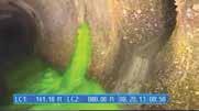
DYED WATER TESTING 4" and up
FLOW ISOLATION (NIGHT RAIDS)
(CCTV) INSPECTION
4" to 24" (practical), but could be used at any size
Introduction of harmless, non-toxic chemical smoke into isolated regions of the collection system and distributed through test section by large blowers. Defects photographed and cataloged by crew. Requires public notification.
Introduction of dyed-water to verify leaks, voids and cross-connections between the sanitary sewer and the storm sewer. Often performed in tandem with a CCTV inspection.
Wastewater flows used to determine dry weather diurnal flows, wet weather I/I flows for master planning, projection of capacity requirements and identification of deteriorated pipelines on a mass scale.
Identifies inflow points. Escaping smoke helps identify uncapped cleanouts, storm drain interconnections, poorly fitting manhole covers, roof leaders and—under certain conditions—broken main sewer and house lateral pipe.
Correlates estimated flow rates from storm sewer system to sanitary sewer. Can also identify locations where flow is transferred from the sanitary sewer to the storm sewer and determine the presence and location of leaks in, or voids around, the pipeline.
4" to 120"
Between midnight and 6 a.m., measure flow rate in each influent sewer in the manhole at the most downstream location of the test basin; flow in the sewer at this time is attributable to infiltration through leaking joints and broken sewer pipes. Continue working upstream along each pipeline branch where significant flows are measured until flow becomes minimal.
Digital cameras provide ability to quantify pipeline defects and perform “virtual” pan and tilt to focus inspection on any potential defect.
Identifies high rates of groundwater infiltration. Reaches with significant flow changes to be further evaluated.
LASER PROFILING (LIDAR) 18" to 144"
SONAR PROFILING
18" to 144"
Above water inspection in pipelines, typically collected at a rate of 12x/second.
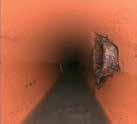
Longitudinal pipeline cracks, circumferential cracks, fractured pipe, offset joints, roots, vertical and horizontal misalignments, broken lateral connections, protruding taps, rodents and vermin, etc.
Identifies loss of pipe wall due to corrosion. Quantifies ovality of pipe. Compares deflection versus design in horizontal and vertical directions.
Assess pipelines that continuously operate in a high flow condition, such as siphons and force mains. Typical collection rate of 1x/second.
Calculates debris levels and volumes in pipe for quantification of subsequent removal costs. Helps determine whether pipe capacity issues can be addressed by cleaning, or if pipe upsizing is needed. Identifies major structural anomalies.
CLOSED-CIRCUIT TELEVISION
Condition Assessment Technologies for Gravity Pipes
EXPECTED INFORMATION
MULTI-SENSOR DATA COLLECTION 18" to 144"
RADAR 18" and up
INSPECTION N/A
LATERAL INSPECTION 4" to 6"
6"
FOCUSED ELECTRODE LEAK LOCATOR (FELL) 6" to 60"
N/A
N/A
Common to provide concurrent high-definition CCTV, LIDAR and sonar inspection. Typical collection rate of 6x/second. Consider completing all three inspections concurrently, even if only one is specified, to allow subsequent recovery of additional data if determined valuable.
This in-pipe inspection tool applies the same principals of ground-penetrating radar and can be combined with concurrent CCTV and laser profiling. Radar signals are directed toward the pipe wall, then reflections and refractions are measured to identify material interfaces. Can extend to 5 feet beyond the pipe wall and measure to an accuracy of ± 1/8 inch.
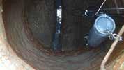
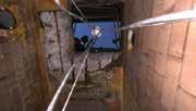
Visual inspection can be completed without entering manholes to determine moderate to significant manhole defects. Tools such as remote CCTV cameras can be used to enhance inspection without requiring manhole entry. Manhole entry can be performed to provide more detailed inspection and testing.
Specialized CCTV camera equipment allows inspection of laterals where cleanouts are provided. Mainline CCTV equipment can inspect areas around each lateral connection with good results.
Tests pipe joints for integrity as part of I/I reduction.
Uses electrical currents to determine if leakage or infiltration potential exists. Requires flow interruption to fill the pipe with water for testing.
High-definition cross-section images and measurements at every 50 feet and at significant defects, as determined by the CCTV operator. Also can measure hydrogen sulfide, temperature and other data.
Pipe wall thickness, variation in pipe wall thickness (indicative of corrosion), voids outside the pipe. For non-metallic pipe only.
Determines I/I leakage potential through use of vacuum. Requires interruption of sewer flows.
Reveals structural integrity of manholes, signs of historic surcharge and signs of I/I (root intrusion, stains and active water flow). May also help identify blockages that can be cleared to reduce SSOs.
Identifies lateral defects similar to mainline CCTV.
Uses high voltage instruments to determine integrity of manhole linings. Technique requires manned entry and flow interruption.
Determines the extent of joint leakage and helps prioritize rehabilitation. Often done in conjunction with a chemical grouting operation.
Indicates joints and other portions of pipe where water is electrically connected to the ground.
Indicates which manholes are not completely sealed and might be sources of I/I.
Provides information regarding lining integrity.
PIPE PENETRATING
MANHOLE
JOINT PRESSURE TESTING
to 42"
MANHOLE VACUUM TESTING
MANHOLE HOLIDAY (SPARK) TESTING
Pipeline Rehabilitation
Pipeline Rehabilitation Technologies
METHOD
OPEN CUT REMOVE AND REPLACE
CURED-IN-PLACE PIPE (CIPP)
SLIPLINING
PIPE BURSTING
PIPE REAMING
CLOSE-FIT LINING
DIE-DRAW LINING
ROLL-DOWN LINING
FOLD-AND-FORM LINING
DESCRIPTION
Traditional method of excavating trench, installing bedding, laying pipe, backfilling and replacing pavement.
Inserting a felt liner impregnated with a thermosetting resin inside an existing pipe to form a new structural pipe inside the old pipe. Fiberglass reinforcement may be used to reduce thickness of liner in gravity pipes. Fiberglass, polyester or carbon fibers can be used for pressure pipe applications.
ADVANTAGES
• Proven approach for thousands of years.
• Built to current standards.
• Sequencing work may avoid bypass.
• Numerous experienced contractors result in competitive pricing.
Placement of a solid continuous or segmented pipe inside an existing pipeline. Typical materials include HDPE, PVC, FRP, steel and VCP.
• Provides a fully structural replacement pipe with proper design.
• Small reduction in cross-sectional area.
• Smooth interior with no joints typically improves flow capacity.
• Installed from maintenance holes, therefore no entrance or exit pits are needed.
• Liners can be cured with hot water, steam or ultraviolet light (which may also provide strength and environmental advantages).
• Grouting not required due to tight fit or very small annulus.
• Accommodates bends, deformations in existing pipe and non-circular conduits.
• Lateral connections reinstated robotically.
• Numerous experienced contractors result in competitive pricing.
• Used for non-structural and fully structural rehabilitation.
• If butt fusion pipe is used, the number of joints is minimized or eliminated.
• Typically, only one pit is required (to pull pipe into the line).
• If segmented pipe is used, sewer flows may not require interruption.
• Less costly than installing a new pipe, particularly as burial depth increases.
Technology that replaces an existing pipe by breaking the old pipe and replacing it by inserting a new pipe of equal or large diameter.
• Allows existing pipe to be upsized.
• Up to 25% less expensive than open cut.
• Maintains existing pipe alignment.
• No disposal needed, as existing pipe fragments are left underground.
• Reduces surface and community disruption.
Inserting a plastic pipe (HDPE or PVC) inside an existing pipe, either by folding the new pipe (U-shape) or by pulling the new pipe through a reduction die to temporarily reduce the diameter of the new pipe.
• Provides a fully structural replacement pipe.
• Small reduction in cross-sectional area (can install thin wall liners).
• Excavation pit may not be required for smaller diameters.
• Liner remains in tight contact with the inside of the host pipe; no grouting needed.
• Adds more competition among lining methods.
• Requires less downtime than CIPP.
• Accommodates large radius bends.
• Significant surface, socioeconomic and environmental costs.
• Potential community disruptions, including traffic, noise and dust.
• Significant geotechnical requirements.
• Often requires new alignment.
• Parallel pipes are difficult to add in congested corridors and increase O&M costs.
• Requires flow bypass.
• Relatively high unit costs.
• Obstruction can inhibit the installation process.
• Failures may occur due to improper wet-out, delays in transport, equipment failure during curing operations, poor design, lack of cleaning and hydrostatic forces.
• Styrene may be a byproduct of some liners; can be potential issue for odor complaints and has been identified as potential to interfere with wastewater treatment biological processes.
• Certified inspectors are highly recommended to monitor and inspect materials, installation and curing operations.
• Significant reduction in cross-sectional area of pipe; large annulus.
• Insertion and reception pits may be needed.
• Bypassing may be required.
• Lay down area for butt-fused pipe is required.
• Generally can’t pass through inflection points.
• Laterals must be reinstated externally (open excavation).
• Grouting of annular space may be required.
• Failures may include separation of pulling head from pipe, joint failure, excessive pulling loads leading to pipe failure and missed laterals.
• Needs geotechnical information in pipe zone and trench over the pipe. Insertion and reception pits may be needed.
• Potential for heaving or settlement depending on soils.
• Lateral reconnection by open cut is required.
• Failures may be caused by equipment breakdown, insufficient ground cover, curved pipes, narrow previous trench and rocky soils.
• Bursting system components undersized or not compatible with the application.
• Bypass required.
• Pit excavation may be required for installation.
• Lay down area for butt-fused pipe is required.
• May not be suitable for existing pipes with bends more than 22.5° (pits must be excavated for larger bends).
• Relatively higher cost compared to other lining methods.
• Infiltration may follow annular space.
• Failures can result from operator error, equipment failure, improperly sized pipe and liner slippage in service.
• 4" to 120" for gravity pipes
• 6" to 54" for pressure pipes
between access holes
• Up to 60" for HDPE and PVC
• Up to 120" for FRP/GRP
• Up to 144" for steel
Varies with site conditions and material
Pipeline Rehabilitation Technologies
METHOD
SPIRAL WOUND LINING
CENTRIFUGALLY CAST CONCRETE PIPE LINING (CCCPL)
GEOPOLYMER LINING
MANUFACTURED IN-PLACE COMPOSITE PIPE (MICP)
DESCRIPTION
Strips of ribbed PVC are spun inside an existing gravity pipe to create a new pipe within the old pipe.
Mechanical cleaning followed by centrifugally applied Portland cement-based binder with a complex formulation of pozzolans, admixtures, crystalline forming mineral, rheological admixtures and reinforcing fibers. The binder is mixed with carefully graded select silica sands.
ADVANTAGES
• Adds more competition among lining methods.
• Can be used for non-circular conduits.
• Accessible through existing manholes.
• Can negotiate bends between access points.
• Improves flow coefficient.
• Relatively long installation lengths are possible.
• Provides a fully structural replacement pipe with proper design.
• Small reduction in cross-sectional area.
• No joints and smooth interior.
• Accommodates non-circular pipes, bends and deformations in existing pipe.
• Short curing time shortening bypass time.
• Can be fortified against MIC with an antimicrobial admixture.
• Crack healing assisted by crystalline forming mineral admixtures.
• Great short term mechanical properties, including compressive and flexural strengths.
• Proven method since 1996.
Cleaning followed by a spin- or sprayapplied fly ash based binder with aluminosilicate, other lime containing minerals, alkalies and other admixtures along with fine-grained aggregates. Some are fiber-reinforced.
• True alumina silicate condensations in the lab where highly refined raw materials are used along with high curing temperatures.
• Accommodates non-circular pipes, bends and deformations in existing pipe.
• Short curing time shortening bypass time.
• Products have evolved over the past few years and their short term mechanical properties approach those of the industry standards.
• More resistance to direct acid contact than Portland cement-bonded products.
• Potential use in mild acidic industrial applications where pH <5.
Robotically installed composite system comprised of a closed-cell elastomer, high tensile carbon fiber filament and a high tensile rigid layer. Installed using autonomous navigation and control as well as a synergetic matrix of sensor feedback for real-time design validation.
• Reduces long term creep effect and material fatigue.
• Fills and seals any annular space or other discontinuities.
• Absorbs and shields rigid layer from strain caused by seismic events.
• Reports exact liner thickness and fiber pitch, 360 degrees in real-time during installation.
• Structurally independent (AWWA Class IV) renewal solution.
• Radial and axial carbon fiber reinforcement.
• Lining of 0 to 90 degree bends without excavation.
• Unlimited internal pressure rating.
• Zero annulus – minimal diameter loss.
• Autonomous control with auto correct platform eliminates ‘applicator error.’
• Significantly reduced environmental and public disruption.
• Reduced installation times.
• Utilizes excavated or manway accesses.
• Does not require confined space entry.
LIMITATIONS
• Relatively high cost compared to other lining methods.
• Specialized personnel required to operate winding equipment.
• Continuous fusion, solvent-welded or mechanical joints are required.
• Annular space must be grouted.
• Potential failures caused by equipment breakdown and unexpected obstructions.
• Surface cleaning and preparation needed. Products are not for use against direct acidic conditions.
• Bypass may be needed.
• Active infiltration needs to be addressed prior to application.
• May require confined space entry.
• Some materials may be costly.
• Not for certain industrial processes or structures where upstream acidic production occurs in significant quantities.
• Bypass may be needed.
• Active infiltration needs to be addressed prior to application.
• May require confined space entry.
• Current products offered are hybrids; may compare their properties to simple Portland and sand mortars.
• Difficult to determine where it is resistant enough for typical municipal applications. One manufacturer suggests corrosion rates of 3" in ten years.
• Areas with severe MIC can produce acid concentrations nearing 7% with pH near 0.
• Autogenous crack healing not well studied.
• Bypass required.
• Pit excavation may be required for installations without existing access points.
• Limited applications to date.
Pipeline Rehabilitation Technologies
METHOD
SPRAY-APPLIED POLYMER LINING
SPOT REPAIRS
CHEMICAL GROUTING
CEMENT MORTAR LINING
CROWN SPRAYING
DESCRIPTION
Mechanical cleaning followed by spray-applied product, epoxy, polyurethane or polyurea.
Methods for repairing short sections of pipe. Common methods include internally or externally applied fiber-reinforced polymer and internal seals.
Uses a packer and grouter to stop infiltration, close small voids and/or test the seal of individual gravity pipeline joints. Special shape and size packers can be designed and constructed.
• Minimal surface disruptions.
• Small reduction in cross-sectional area with internal repairs.
Mechanical cleaning followed by spray-applied mortar, per ANSI/ AWWA Standard C602. Oldest pipeline rehabilitation method, introduced in the 1960s.
• Proven method.
• Relatively low cost.
• Does not require bypassing.
• Not affected by active infiltration.
Application of magnesium hydroxide to protect concrete gravity sewers and retard corrosion.
• Thick linings are not proven to serve as fully-structural rehabilitation.
• ANSI/AWWA Standard C620 exists for 1 mm epoxy lining only.
• Requires excavation for external repairs.
• High unit cost due to limited length of pipe repair.
• Not a structural rehabilitation.
• Subject to failure when used in areas with fluctuating groundwater levels.
• Failures can result from operator error, equipment failure and improper mixing.
• Use of grout materials may be restricted in the future.
• Minimal structural improvement.
• Only applicable to unlined cast iron and steel water mains.
• Not recommended for soft water.
• Temporary (1-2 year expected life).
• Only protects the pipe above the flow zone.
on packer length space.
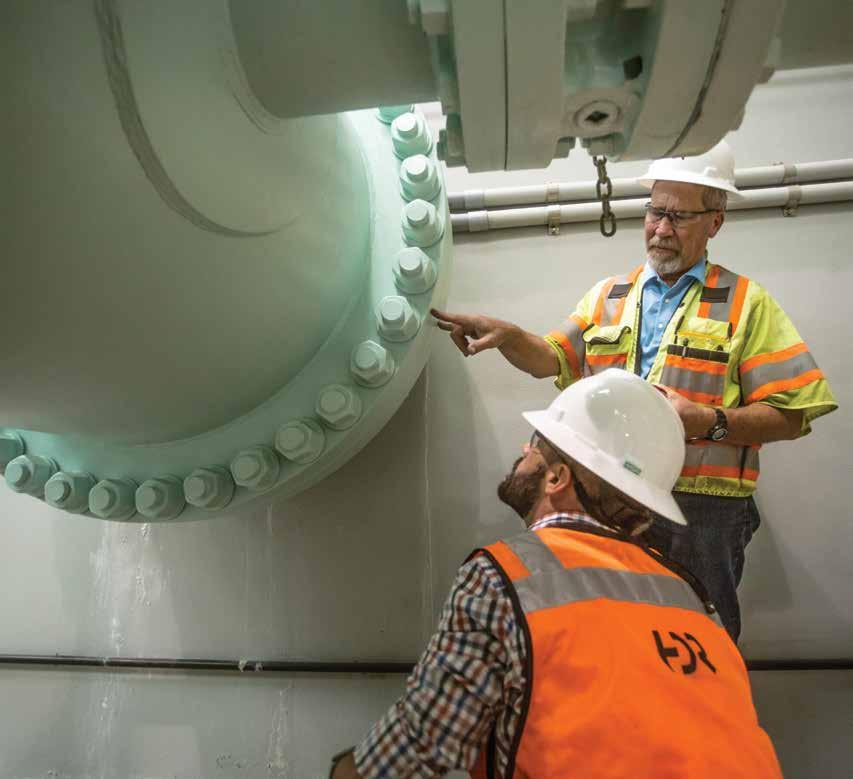
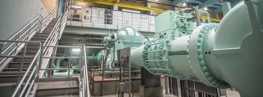
Treatment Facilities and Pump Stations
Facility conditions impact maintenance levels, power consumption and system performance.
Condition assessments for water and wastewater treatment facilities require a complete evaluation by a multi-disciplined team to define needed facility improvements, prioritize or schedule the improvement projects and estimate their costs. The best approach
includes a trained and experienced team working interactively with utility management and operations and maintenance staff.
Performing a condition assessment on a pump station helps identify components that may need to be repaired or replaced to ensure continued service and reliable operation.
Common Reasons to Assess Conditions at Facilities and Pump Stations
“ I need to develop a Capital Improvement Program.”
"I don't have enough budget to replace all of the aging or failing equipment."
“Which projects do I focus on first?”
“I want to extend the life of my equipment.”
Maintain or Replace… or Upgrade
Utilities routinely face the dilemma of repairing versus replacing a broken piece of equipment. When the equipment breaks, there is very little time to evaluate a third option: should it be upgraded to meet performance requirements?
A condition assessment can proactively help to resolve this three-dimensional dilemma. It can look at asset and system performance, in addition to the more traditional condition and reliability parameters while immediately addressing major deficiencies.
Prioritizing Projects
(Likelihood of Failure) x (Consequence of Failure) Almost all condition assessments at treatment plants and pump stations use some version of this formula.
Likelihood of Failure
Think of this as the condition of the asset. What is the chance that it will break down? It is a combination of many factors, including age, maintenance history and working environment. A condition assessment can provide a numerical rating to better understand this risk.
Consequence of Failure
What happens if an asset breaks? It may not only impact plant performance, but also seriously impact customers, businesses and the environment. One breakdown might not have an impact because of redundancy, but another may cause a citywide water outage. These must be evaluated and prioritized.
“ Which breakdowns are most likely to shut down my entire facility?”
“ I don’t have much information on my equipment.”
“ I need an asset management program but don’t know where to start.”
Tools for Above Ground Infrastructure
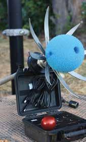
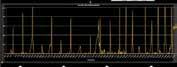
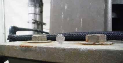
Vibration Analysis
Maximum recommended vibration for most pumps is between 0.17 and 0.34 in/sec and will vary depending on pipe size and style. Vibration analysis techniques can vary from “rule of thumb” to highly complex.
Is your pump RPM at the critical speed? If so, you may get resonance and excess vibration. Use specialized equipment to test this, especially if you use a variable speed drive.
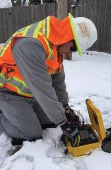
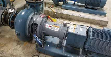
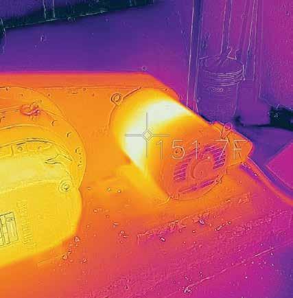
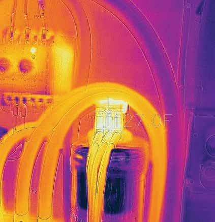
Thermal Imaging
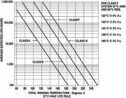
Measuring temperatures of motors and electrical equipment provides important information about their condition.
Did you know that for every 10° C (18° F) increase in motor temperature, the life of the winding insulation is reduced by 50%?
A standing nickel generally means that vibration is < 0.1 in/sec.
Thermal imaging shows problem areas.
Use of an accelerometer to measure vibration Vibration graphs
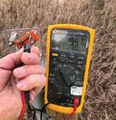
Electrical Testing
While technically still thermal imaging, high resistance electrical connections in switchgear, starters, etc. can become major problems if left unchecked. Thermal imaging can be utilized to detect such “hot spots."
Additionally, ground fault monitoring can also provide insight as to the condition of the electrical distribution system. Phase to ground faults can cause uneven phase voltages leading to reduce motor and equipment life expectancies.
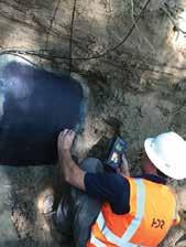
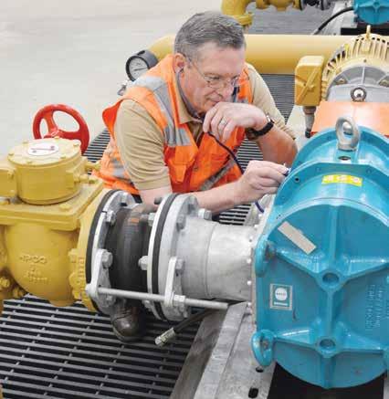
Acoustic Testing
Cavitation of pumps can cause serious impacts to impellers and overall pump performance. The sounds associated with cavitation are not always obvious. Experienced operations and maintenance staff using a stethoscope on the pump volute are able to detect cavitation.
Acoustic Testing Electrical Testing
Condition Assessment for Treatment Facilities and Pump Stations
ARCHITECTURAL
• Building conditions
• Masonry and exterior walls
• Insulation
• Sealants
• Doors and windows
• Roofing systems
• Floors and ceiling
• Paint systems and finishes
STRUCTURAL
MECHANICAL (HVAC AND PLUMBING) COMPONENTS
• Occupancy and life safety
• Accessibility
• Means of egress
• Process structures
• Building structures
• Cast-in-place concrete
• Precast/prestressed concrete
• Structural steel
• Concrete masonry
• Miscellaneous metals, including aluminum and stainless steel
• Equipment foundations and supports
• Piping support systems
• Air handling equipment
• Make-up air units
• Heating equipment
• Cooling equipment
• Ductwork
• Boilers
• Chillers
• Cooling towers
• HVAC controls
• Hot/chilled water systems
• Plant water systems
• Plumbing fixtures and piping systems
• Supply and exhaust fans SUGGESTED ELEMENTS TO ASSESS
• Asset ID and age
• Maintenance history
• Type of construction
• Roof type and condition
• Exterior walls and insulation condition
• Interior walls condition
• Doors, windows and hardware condition
• Stairs, ladders and guardrail condition
• Coatings condition and corrosion issues
• Accessibility compliance
STANDARDS/CODES
• International Building Code
• International Existing Building Code
• International Fire Code
• International Energy Conservation Code
• NFPA
• ANSI
• ASTM
• FM Global
• Underwriters Laboratory (UL)
• Asset ID and age
• Maintenance staff assessment
• Previous evaluations/inspections
• Exposure and loading conditions
• Overall condition – structural distress or movement
• Concrete sounding and other nondestructive testing methods
• Half-cell corrosion testing per ASTM
• Phenolphthalein testing
• Microstructural analysis per ASTM
• International Building Code
• International Existing Building Code
• American Concrete Institute (ACI)
• American Institute of Steel Construction (AISC)
• American Welding Society (AWS)
• ASTM/ANSI
• SEI/ASCE 11 for Existing Buildings
• SEI/ASCE 7 Minimum Design Loads for Buildings and Other Structures
• Equipment ID, age and nameplate
• Historical maintenance information
• Overall condition and reliability
• Spare parts
• Previous reports/inspections
• Control cabinets and controls
• Fan and heating system performance
• Ventilation issues
• Plumbing issues
• NFPA
• IBC Codes
• Underwriter Laboratory (UL)
• ANSI/AWWA
• ASME/ASTM
• ASHRAE
• NEMA
PROCESS
• Process equipment
• Process basins
• Pumping equipment
• Chemical feed systems
• Valves, piping and pipe supports
• Flow control and gates
• Process efficiency issues
• Ancillary equipment
ELECTRICAL AND I&C
• Switchgear and switchboards
• Site power distribution and transformers cables
• Standby power and transfer switches, UPS systems
• MCCs and VFDs
• Panelboards and disconnects
• Major motors
• Conduits, raceways and conductors
• Lighting systems and emergency lighting
• Grounding and surge protection
• I&C equipment – field devices, primary elements, control panels, PLC’s
• Control approach and SCADA system
• Security systems
• Equipment ID and nameplate data
• Historical maintenance records and operational history
• Asset management information
• Equipment age/normal asset life
• Equipment reliability and impact of failure
• Performance rating and condition
• Spare parts availability
• Previous facility evaluations
• Performance tests – pumps, blowers, etc.
• Ancillary systems – air, seal water, priming, etc.
• State regulatory requirements
• 10 state standards
• Hydraulic Institute
• AWWA standards
• NSF ratings
• ASTM/ANSI
• Asset/equipment ID, age and nameplate
• Visual inspection
• Maintenance history
• Equipment condition and reliability
• Conduit/wire condition
• Equipment suitability for environment
• UPS requirements
• Lighting level
• Primary elements condition
• Data communication
• SCADA controls performance
• Interview plant operating staff
• NEC/NFPA compliance review
• National Electric Code (NEC)
• IBC Codes
• NFPA
• IEEE
• Underwriters Laboratory (UL)
• NEMA/ANSI
• ISA
SITE CIVIL
• Overall site review
• Site access
• Site roads, parking and fencing
• Exterior lighting
• Landscaping
• Storm water management
• Neighborhood concerns
• Site paving
• Site drainage issues
• Site lighting condition and levels
• Landscaping condition
• Site access/control
• Noise/neighborhood issues
• Storm drainage system
• Applicable local standards
• AASHTO
• ASTM
• U.S. Army Corps of Engineers
Pump Performance Testing
Determine Causes for Loss of Pump Output
Pump performance testing helps a utility determine the cause of decreased pump performance. Though decreased performance is often attributed to premature pump wear, in many cases the cause is a constriction — either upstream (clogged intake screen) or downstream (sediment accumulation, entrapped air) — that can be addressed through maintenance.
CURRENT OPERATING POINT (shows increased friction in the system)
Original Pump Curve
Original System Curve
Current Pump Curve
Current System Curve
CURRENT OPERATING POINT (shows decreased pump output due to wear)
There are many potential causes of increased headloss in the system, as shown in the figure to the right. Pressure sensors and portable flow meters at strategic locations can be used to pinpoint specific issues, such as reduced cross-sectional area due to entrapped air (air valve failure) or accumulated sediment.
ORIGINAL OPERATING POINT
In the figure to the left, comparison of the current operating point to the original operating point may indicate either impeller wear (reduced pump curve) or increased headloss in the system (increased system curve).
Periodic Pressure Sensors
Rapid Condition Assessment
If a utility has limited budget or is short on information, it may be appropriate to perform a rapid condition assessment. Facilities can be evaluated at a high level to get an initial idea of the improvements that will be needed. This approach is ideal for smaller utilities or when performing due diligence acquiring new assets.
Evaluation done at system level, not at asset level
One rating for each of six categories: Architectural, Structural, Mechanical, Electrical, Process, Civil
Evaluation by experienced operator or engineer
Do not need detailed information on each asset
Less granularity on issues
Simplified and standardized approach to compare dissimilar systems Inability
or
(*) The state of process technology, availability of applicable reference cost data and many other risks affect the range. The +/- value represents typical percentage variation of actual costs from the cost estimate after application of contingency (typically at a 50% level of confidence) for given scope.
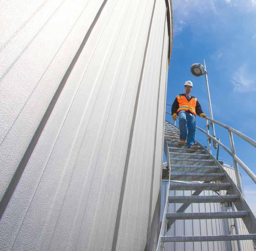
Tanks and Reservoirs
Condition assessment of tanks and reservoirs should be scalable to the utility's available budget and adaptable to shifting priorities. Whether for concrete reservoirs or steel water tanks, an assessment program establishes program goals, prioritizes reservoirs based on triage-level assessments and then provides comprehensive physical and performance evaluations.
Rehabilitation of water storage reservoirs is an important part of a complete facility management and maintenance
plan. Rehabilitation may include sandblasting, repair/ replacement of roof, shell, columns and floor, leak repair, interior and exterior re-coating, cathodic protection and safety and building code upgrades. For reservoirs, rehabilitation focuses on repairing the core of the structure and protecting it from future deterioration. Properly rehabilitated reservoirs will minimize leakage, protect the health and safety of consumers and provide a safe working environment for operators.
1 Inspection Recommendations
INSPECTION TYPE DESCRIPTION
Routine (daily to weekly)
Periodic (quarterly to annually)
Comprehensive (every five years)
2 Triage
Exterior inspection to detect acute changes such as storm damage and vandalism.
Exterior inspection and limited internal visual inspection from hatch to monitor areas of concern.
Internal and external physical evaluation, review of operations and maintenance records and performance evaluation.
STAFF REQUIREMENTS
One staff member.
Two to three staff members. Requires safety procedures and coordination.
Multi-disciplined team, including staff familiar with operations, maintenance, water quality, reservoir design and structural engineering.
Typically conducted in the first few months of a program, a triage assessment is carried out with the tank in service.
P Perimeter and site walk
P Exterior roof assessment
P Interior visual assessment from the hatch
P Review of historical O&M data
P Cathodic protection coatings assessment (steel tanks only)
Water Quality Challenges
CHALLENGE
MICROBIAL
Proliferation of bacteria/bacterial regrowth
Biodegradation of tank coatings and materials
Nitrification
CHEMICAL/PHYSICAL
Short-circuiting/dead zones
Disinfection by-product formation
CAUSATIVE FACTORS
Detention time, temperature, food sources, bacterial sources, lack of residual
Exposure time, surface area, material properties
Temperature, presence of ammonia, detention time, lack of residual
Detention time, common inlets and outlets, insufficient baffles or mixing
Detention time, presence of precursors, presence of excess sediment
Leveraging a Cathodic Protection System for Rapid Condition Assessment
Condition of steel tank coatings can be efficiently assessed using either a permanent current cathodic protection (CP) system, or a temporary system specifically installed for condition assessment. The current applied through an impressed current CP system can be adjusted to the total area of exposed submerged steel below the water level in a steel tank. As the coating degrades over time, the CP current increases.
Suspended Anodes
Atmospheric Area Above the Water Line
Bare Tank (no coating)
1-2 mA/SF
Typical New Tank
<0.02 mA/SF
Submerged Tank Area
Proportion of Uncoated Submerged Steel
Common Steel and Coatings Tests
• Ultrasonic thickness testing of exterior shell, bottom and roof
• Interior and exterior weld inspections
• Pit-depth measurements
AWWA D102 recommends complete removal and recoating at 25% bare (current of 0.25 to 0.5 milliamps per square foot [mA/SF]), or when the atmospheric area above the water line requires recoating. As CP systems do not protect the atmospheric area, recoating of tanks with CP systems is often targeted at protecting this more vulnerable area.
• Visual coating inspection per SSPC-VIS2
• Dry-film thickness measurements
• Adhesion testing per ASTM 3359 Method X-Cut
• Qualitative lead testing
Comprehensive Inspections
Based on triage assessment, tanks are prioritized for comprehensive assessment
Visual Inspection
Internal raft inspection for concrete tanks or dry inspection for steel tanks.
Code Conformance
Analytical evaluation comparing the tank’s condition to design and prevailing codes.
• Concrete – International Building Code references ASCE 7-05 for minimum loads
• Steel – Per AWWA D-100 and SEI/ASCE 11-99
Water Quality Challenges
(See adjacent table)
Ventilation
Calculated per ASHRAE Fundamentals Handbook. Requirements depend on the tank and ambient conditions. Ventilation affects long-term reservoir performance.
Deck Movement
Decks are frequently found to be improperly constrained or not performing as designed. Deck movement can compromise the roof and expose metals to corrosion.
Cracking
ACI 350, Code Requirements for Environmental Engineering Concrete Structures and Commentary, has replaced ACI 318. ACI 350 calls for a higher reinforcement ratio to minimize crack widths and produce water-tight structures.
Leakage
Perform leak tests per ACI 350. Evaluation should also consider liner type and condition, if applicable.
Cathodic Protection Assessment
(See adjacent section)
Steel and Coatings Testing
Will vary according to the tank and level of assessment. Common tests include those shown to the left.
Asset Management
Managing assets is a process that requires a structured approach, defined resources and an ability to adapt to the changing needs of the system. HDR’s approach is flexible and tailored to fit your needs. We succeed when you can make confident and defensible decisions based on your data.
Integrating Condition Assessment into Your Overall Asset Management Program
Asset management is a structured, data-driven approach to optimizing the lifecycle cost of asset ownership and focuses on providing reliable and dependable levels of customer service. Condition assessment is an integral part of the asset management process.
Service Levels
Define measurable goals for services the utility provides from a customer perspective.
Enterprise Strategy
Develop strategy to mitigate risk and meet defined service levels.
Asset Decisions
Document and follow a repeatable process for making decisions on asset renewal, replacement, operations and maintenance.
People and Processes
Develop a systematic approach for the continuous improvement of the workforce to provide value to the asset management program.
Acquire Operate
Risk Mitigation
Develop actionable plans to manage risks of not meeting service levels and reduce threats to asset performance.
Asset Knowledge
Manage asset data through grouping of asset classes in related hierarchies in the computerized maintenance management system (CMMS) and GIS.
Acquire Condition assessment data used to prioritize CIP
Operate Condition monitoring is part of the operating strategy
Monitor Set up and manage a condition assessment plan
Maintain Use condition data to adjust the maintenance strategy
Condition
Assessment Process
• Planning
• Initial evaluation
• Inspection
• Engineering analysis
Rehab Analyze condition trending to develop renewal strategies as part of an asset plan
Retire Plan for retirement based on economic useful life and risk planning
Asset Management = Smart Investment
Successful asset management enables the efficient, strategic allocation of limited resources toward sustainable capital and operational programs.
Asset management is not just about a single project. It is about developing the right tools to leverage data about the condition of your assets to achieve organizational objectives.
Reasons to Create an Asset Management Strategy
RISK MANAGEMENT
• Aging infrastructure
• Uncertainty about when and where to invest
• Loss of knowledge from an aging workforce
Transforming Condition Data into Actionable Decisions
The Asset Management Process Ask Yourself:
What is the current state of my assets?
What is my required level of service?
What assets are critical to performance?
What are my best investment strategies?
What is my best long-term funding strategy?
DESIRED OUTCOMES
• Informed decision-making process
• Predictable, prioritized investment level
• Predictable infrastructure performance
• Regulatory compliance
• Thriving community
• Improved ability to engage stakeholders
• Sustainable infrastructure
HDR develops asset management decision support tools by building a practical and structured process for transforming data into actionable decisions. Our tools store data in an analyzable format to streamline development of reporting dashboards.
DATA INFORMATION KNOWLEDGE DECISION
Raw numbers or images measured; estimate of uncertainty
Context given; details what is measured and when; organized and accessible; filtered and distilled
Application of a model to interpret and understand cause and effect
Acting on knowledge to achieve benefit
Asset Management and Water Distribution Systems
Extending asset life varies among utilities and depends upon factors such as system performance, size and effectiveness of a utility’s historic renewal program and physical characteristics such as material quality, construction quality, system age, strength of deterioration sources and stresses (internal and external). These characteristics and condition assessment data can be evaluated to identify priorities and cost-saving alternatives to replacement such as pressure reduction and corrosion protection.
Recent advances in analytical techniques can support utilities to better understand and communicate investment scenarios by forecasting level of service several decades into the future including breaks per year, break response staff needs, customer outages and flow not delivered.
As utilities evolve, implementation of utility-wide condition assessment and renewal strategy is appropriate to cost-effectively sustain desired service levels while avoiding future rate shock when addressing aging infrastructure.
Water utilities in the U.S. replace approximately
0.37% of their pipelines each year.*
*AWWA 2003, AWWA 2011
At this pace, it would take roughly 270 years to replace an entire system.
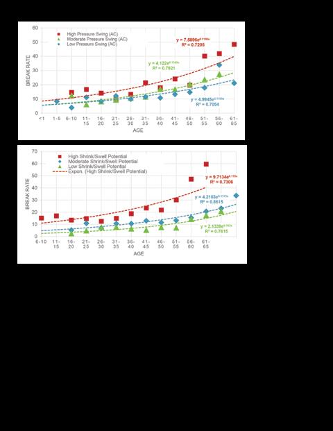
Variation in deterioration rates can be measured using historic break data to quantify which factors drive some pipes to deteriorate faster than others. At this utility, pipes exposed to excessive ground movement (high shrink/ swell) and pressure variations (high pressure swing) deteriorate faster and will have a shorter life.
Hydraulic Model
Measure C onsequence
Not all failures are created equal. By fully leveraging an existing hydraulic model, utilities can cost-effectively quantify the consequence of failure for each pipe in the systems in terms of customer outages, critical customer outages, water lost and demand not delivered.
Collect the right data. When a pipe is exposed (e.g. break response, new tap installation, pipe renewal, appurtenance renewal), it provides a unique opportunity to cost-effectively gather condition assessment data (e.g. pipe samples, photos, soil samples) that can be crucial in making effective pipe management decisions.
Asset Management and Wastewater Collection Systems
The true renewal need for wastewater systems varies widely from utility to utility and depends on system performance, regulatory drivers and system characteristics. Age alone is not a good indicator of investment needs for replacement or extending asset life. Analytical tools and decision logic can be applied to wastewater condition assessment data to support improved decision making for managing assets by balancing cost, risk and level of service.
Effective programs incorporate condition assessment data and risk to optimize operations and maintenance. Condition data can be applied to increase or reduce the frequency and type of preventative maintenance programs to manage risk, extend asset life and save resources.
• Root Medium
• Crack Longitudinal Narrow
• Root Heavy
• Joint Separate Small
• Crack Spiral Narrow
• Joint Separate Medium
• Crack Circular Wider
• Crack Longitudinal Wide
• Broken
• Crack Multiple Wide
• Joint Gasket Medium/ Joint Offset Medium/ Small Collapse
• Cavity Large
• Liner Failure Detached
• Joint Gasket Severe/ Joint Offset Large
CUMUL ATIVE COS T
With competing goals, asset management helps manage complexity and use resources efficiently.
Affordability
System Needs/ Service Goals
Acceptable Risk Levels
Looking for More Guidance?
We’ve conducted research, served on committees and translated manuals. More than any other consultant, HDR has advanced the practice of water main condition assessment. If you want more guidance on condition assessment and rehabilitation, please contact us at water@hdrinc.com, or access our recommended reference documents at hdrinc.com/AssetLife
hdrinc.com
The Water Research Foundation
• Acoustic Signal Processing for Pipe Condition Assessment (Report #4360)
• An Assessment of Water Distribution Systems and Associated Research Needs (Report #706)
• Answers to Challenging Infrastructure Management Questions (Report #4367)
• The Assess-and-Fix Approach: Using Non-Destructive Evaluations to Help Select Pipe Renewal Methods (Report #4473)
• Asset Management Research Needs Roadmap (Report #4002)
• Criteria for Optimized Distribution Systems (Report #4109)
• Development of an Effective Management Strategy for Asbestos Cement Pipe (Report #4480)
• Distribution Infrastructure Management - Answers to Common Questions (Report #2629)
• Distribution System Security Primer for Water Utilities (Report #2931)
• Effects of Electrical Grounding on Pipe Integrity and Shock Hazard (Report #913)
• External Corrosion and Corrosion Control of Buried Water Mains (Report #2608)
• Failure of Prestressed Concrete Cylinder Pipe (Report #4034)
• Global Review of Spray-On Structural Lining Technologies (Report #4095)
• Investigation of Pipe Cleaning Methods (Report #2688)
• Leveraging Data from Non-Destructive Examinations to Help Select Ferrous Water Mains for Renewal (Report #4471)
• Managing Infrastructure Risk: The Consequence of Failure for Buried Assets (Report #4451)
• No-Dig and Low-Dig Service Connections Following Water Main Rehabilitation (Report #2872)
• Optimizing Corrosion Control in Water Distribution Systems (Report #2648)
• Retrofit and Management of Metallic Pipe with Cathodic Protection (Report #4618)
• AWWA Manual M77: Condition Assessment of Water Mains
• AWWA Manual M28: Rehabilitation of Water Mains, Fourth Edition
• NASSCO and WEF's Trenchless Technologies and Asset Management Manual of Practice
• NASSCO's Pipeline Assessment Certification Program Reference Manual
We practice increased use of sustainable materials and reduction of material use.