Retroftted to a less stringent U-value of 0.35 due to complications with an internal insulation strategy.
RETROFIT OF 1960S BRICK CAVITY WALL (N-FACING)
In winter 80% relative humitidy is reached, which is the where mould might begin to form. However during the summer months the wall dries out, so with the cork insulation used this will prevent the degredation of the wall.
Cork doesn't rot, therefore this material is used particularly an infll insulation within the cavity, as moisture build-up is most likely to happen here.
RETROFIT OF CONCRETE FLAT ROOF - WARM
Need to consider if the structural integrity will be compromised due to the added weight from the insulation & green roof.
By installing a green roof, this can reduce the need for artifcial cooling systems (Wilkinson, 2021).
Test 1: insulating the cavity with cork granules. - graphs taken from cold face of cavity insulation.
Test 2: Further insulating internally to reach EnerPHit standards. - graphs taken from cold face of internal insulation.
RETROFIT OF 1960S CONCRETE FLOOR
To reach EnerPHit U-values, the foor thickness must increase by 145mm. (cork slabs come in 20mm increases)
MECHANICAL SYSTEMS STRATEGY
PLANT ROOM
Every building on site requires its own plant room, containing:
• Heat pump room (heating & hot water) (cooling?)
• MVHR connected to external wall (air)
• Distribution board (electricity)
HEAT PUMPS
As the district heat network only keeps water temperatures around 30 degrees, each building requires an independent heat pump, with a heat pump room 3x2m footprint that sits inside the plant room.
MVHR
MVHR will be used to ensure high indoor air quality even in winter months.
SUPPORT FROM MATERIALS & ELEMENTS
"Using a natural material that is able to moderate and regulate the temperature and humidity passively, can contribute to a reduction in heating and cooling energy footprints by up to 5% and 30% respectively" (Haddad, Lannon and Latif, 2024, p.4)
EXTRA STRATEGIES REQUIRED
Extraction system for workshops.
storage requirements for sorting hall.
WORKSHOPS
Due to the materials used within the workshop, extra systems are needed, ontop of the plant room with the MVHR unit, distribution board and heat pump connection.
Both in the timber workshop and chemical workshop an extra extraction system is required, with an external unit. The timber workshop only requires dust extraction, however the plastics & chemicals workshop requires pollutant extraction too.
WASTE CENTRE
The sorting hall requires the storage of certain materials that need special storage requirements for safety.
ZERO-WASTE HOUSING
DESIGN FOR THE FUTURE - ACCESSIBILITY
internal environment F
Buildings must be designed to last for at least 200 years (Dark Matter Labs, 2023), making it crucial that they are adaptable for future needs. Furthermore, in the case of Barton-le-Clay's neighbourhood, there is a growing demand for housing options suitable for older residents looking to downsize.
To address this need, the entire ground floor of these homes has been designed to meet Part M, Category 3 accessibility standards. This ensures that the space can accommodate a variety of living situations, not just those of older adults. For example, the ground floor could function as a self-contained flat, or a larger family could live alongside an elderly relative. Additionally, the Part M-compliant bedroom could be used as a second living room or study - now often desired as remote working becomes more prevalent.
SUMMARY OF DESIGN FEATURES
• A centralised layout to avoid passages.
• Central circulation zone >1500mm to allow for 180° turning space at any point (900mm minimum, 1200mm is 90° turning space).
• <4.8m to public footpath
• Level access throughout
• Key facilities designed to accommodate disabilities
• Easily adapted internal walls
• Opening specified that are sufficient for use from a wide range of people.
CONCLUSION
In attempting to create a housing model that accommodates a wide range of typologies and has options for future adaptability, other challenges have emerged, which will be discussed later in the report. It may be more effective to design several types of house, tailored to specific needs, as one house cannot meet every target, requirement and situation.
Doors open on a hinge rather than sliding as external sliding doors would be too heavy.
Part M principal bedroom
• Clear access to window
• Access route of 750mm around the bed
Part M compliant bathroom layout also gives the possibility for another door to be added in-between bedroom and bathroom for easier access.
Shallow services and storage access with adjustable shelves.
Although the housing part of the site is a no car zone, people who are disabled are allowed to drive their vehicles up to their house. There is space for parking in front of the house instead of the growing garden however this is discouraged. Parking options are given close by for blue-badge holders.
>1500mm between door swings
All windows start below 850mm high so those in wheelchairs have views out.
Flexible living room and dining layouts to ensure compatibility with a wide range of people.
1200mm clear space in front of all kitchen units and appliances.
Ample kitchen space for under-counter storage. Adjustable counter heights so counter can be at the max. height of 900mm.
Worktops should have knee-hole spaces 600mm deep to enable a wheelchair user to pull right up and use the whole width of the worktop (The University of Edinburgh, 2015).
Level access all the way into the building, to ensure easy access. Tiles are specified for the path and the sunspace to ensure a hard surface makes it easier for those using a wheelchair or mobility device.
Entrance route should be lit to 100 lux (The University of Edinburgh, 2015).
FIRE & LIFE SAFETY
internal environment I
As low-density housing no more than three stories, there are less regulations in place compared to higher stories. The requirements specified are regardless of height. In particular, separating elements - floors and party walls - must prevent the spread of fire.
FIRE PROTECTION
All structural elements including party walls and separating floors are required to meet a 60 minute fire rating. Any internal walls, as well as doors to habitable rooms off the escape route need to have a 30 minute fire rating.
Clay plaster is the most common internal finish in these homes. It achieves Class 0 surface spread of flames protection, meaning the internal lining of the residential spaces are protected sufficiently for 60 minutes and possibly longer (Clayworks, no date).
PARTY WALLS OF STROCKS
Preventing spread between terraces.
Strocks are unfired clay, so in the event of a fire they just become more like a fired brick, getting stronger whilst also remaining inflammable (Strocks Fire Resistance, 2024). No risk of combustion or spread of flame. This makes them highly fire resistant, even if exposed, therefore no other fire resistance is required.
The party walls are constructed as two leafs with a cavity in-between to prevent the transfer of sound. Therefore cavity closers are used to prevent the spread of fire within the cavity, particularly at junctions and in separating floors. These walls must increase 325mm above roof height to prevent the spread of fire across the roof.
FIRE ESCAPE & FUTURE PROOFING:
Fire regulations are getting stricter due to the Grenfell inquiry, however most of these are applied to buildings over 11m or 18m high. However, all residents should still be instructed on fire safety and fire doors, with clear signage also to ensure external access routes remain clear for fire services (addressed earlier in the report).
Each terrace will have it's own fire alarm system with an alarm in every room.
Separating wall needs to meet a 60 minute fire rating.
All habitable rooms have an emergency escape window or external door,
Approved Document B outlines for:
• sufficient alarms and means of escape in the event of a fire
• preventing the spread of fire & preventing premature collapse
• sufficient access for the fire service, its appliances and facilities in buildings to help fire fighters
• providing fire safety information to building owners and residents (HM Government, 2022)
Different occupancies (2 flats), needs to be 60 minute fire separation between floors (HM Government, 2022). See 1:10 detail to see what materials are specified.
As a third storey higher than 4.5m, it potentially needs to have a protected staircase to exit safely. Therefore with a loft conversion the current staircases should to be separate from the main living space to prevent the spread of fire. This needs further investigation with a fire engineer.
Entrances for flats are kept separate and no facilities are shared to meet fire regulations. This allows the stairs to be treated as a fire-safe block.
There must not be a common escape area, unless all flats are separated from the escape route. Otherwise, in the event of a fire on the ground floor, anyone on the upper levels would be trapped.
With a loft conversion, a fire door and compartmentalised stairs are required here to meet fire regulations.
The loft is less than 11 meters high, so no extra regulations if converted.
Any staircase must be private, not shared by more than one flat, otherwise would need to separate each flat from the staircase to protect the spread of fire.
* Potentially does not comply as this floor is above 4.5m from the ground. Consult a fire engineer for more information as its unclear.
STRUCTURAL DESIGN STRATEGY: OVERVIEW
construction A & B
HYBRID CONSTRUCTION
Minimise waste but celebrate site & local vernacular
ON SITE CONSTRUCTION USING WASTE & NATURAL MATERIALS
• slow process but celebrates site & using local waste materials which saves money in material cost (even though more cost with labour)
KEEPING FINISHES LOCAL:
OFFSITE MANUFACTURE OF PANELS
MINIMISING WASTE
+ CUSTOMISABLE FINISHES WITH LOCAL MATERIALS (IE PLASTER/CLADDING)
• quick process done in a factory that is not weather Dependant and minimises waste (inhouse processing of waste so most gets used)
TRADE OFF between:
Building with panels - less natural materials as likely tape will be used, however more efficient in building as waste is easier to manage.
Building on-site - creates more waste as need to order products to site, Between 10-30% of materials delivered to UK construction sites are wasted due to over-ordering, damage or loss (Letcher and Vallero, 2011).
STRUCTURE
MATERIALS STRATEGY
Sizes of circle demonstrate proportion of material within the construction strategy.
Strocks made on-site
Local/vernacular finishes
Off-site panels, depending on regional material availability
Foundations from K-Briq's (following their future regional strategy)
Timber structure
materials not yet manufactured in the UK (eg recycled foamglass)
Terraced
Terraced house
STRUCTURAL DESIGN STRATEGY: OVERVIEW
construction A & B
TERRACED HOUSING
Uses less materials & more energy efficient
Designing houses as terraces is important because shared party walls reduce the amount of material required. While the L-shaped design slightly mitigates this advantage, the impact is lessened by incorporating handed terraces.
For optimal form and efficiency, terraces should be arranged in rows of at least six, with sunspaces positioned at the outer corners.
In addition to material efficiency, terraces also help reduce the impact of wind loads by acting as a unified structure. Working with the strock walls, this creates a robust and stable structure that ensures the building will remain durable and structurally safe.
NEXT STEPS
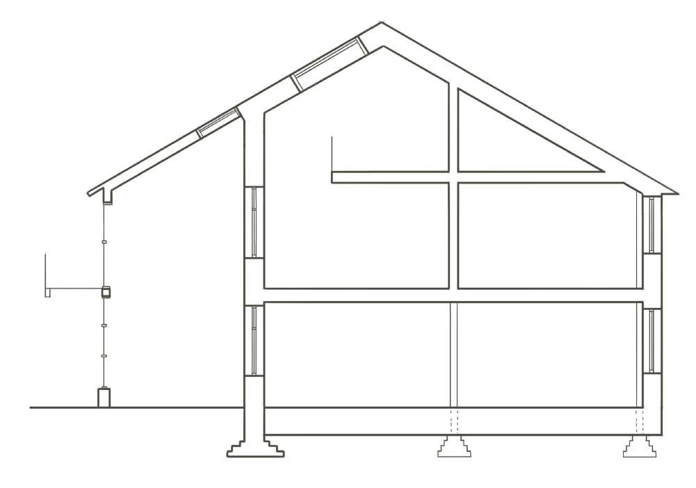
The house has been designed with a post-andbeam structure. This will be investigated next.
Row of handed terraces.
LOADS
LATERAL STABILITY
The strock walls going in both directions offers very good stability, resiting lateral loads from any direction.
0%
75% materials must be sourced from the UK. LBC
70% by weight of building can be reused, recycled or backfilled at its end of life. European Directive on construction & demolition waste, taken from Active House.
STABILITY IN POSTS
To ensure lateral stability and minimise thermal bridges in the timber posts:
Cork insulation at edges
Stepped foundation with K-briq's.
Timber post buried into earth floor to stop lateral stability
Metal plate possibly needed underneath post to ensure stability.
Structural foamglass blocks underneath to prevent thermal bridges.
TIMBER STRUCTURE CALCULATIONS
construction A
The timber structure calculations have been carried out as though the whole structure is timber post-and-beam. In reality the external walls will take many of the loads (instead of timber posts), however the posts that will take the most loads are situated in the middle of the construction anyway, and therefore the results are unaffected and remain accurate.
Tests were carried out to see which way the beams and joists would span, as well as to specify their required size to suitably account for stress and deflection.
LESSONS LEARNT:
• Glue-laminated timbers would mean less chunky beams BUT requires glue (though would mean being able to use lower quality wood - this is a trade off).
• Using lower grade wood is less strong but more readily available (particularly relevant when picking local materials)
CONCLUSIONS
The primary beams will run between terraces (E/W) They will be under more stress therefore it is usually best to have the shorter span so they can carry loads to the columns as directly as possible. This makes the joists run longer widths of 4.8m.
Since some of the primary beams are instead the strock wall taking the load, the joists will need to be hung on joist hangers. With the placement of the windows for maximum daylighting & passive solar gain this fits better with the proposed design.
Next steps:
I've decided to use I-joists instead of solid timber as this uses less material.
CALCULATIONS:
FLOOR BEAMS ACROSS (E/W) - 3.6M
SPAN
4.8m span for joists
3.6m span for beams
Floor beam calculation:
• generally the depth needs to be above 250mm which means glulam! (breadth is not as important) - potentially because joists are spanning a long distance of 4.8m!
• after more testing - found that 250mm depth x 200mm breadth is acceptable - but this is not that common a piece of timber? (more common is 225mm which is unacceptable for bending stress and deflection)
FLOOR BEAMS (N/S) - 4.8M SPAN
3.6m span for joists
4.8m span for beams
Floor beam calculation:
• joists span less so can be smaller (150x75)
• BUT floor beam spans are longer so still require glulam
RAFTER & ROOF BEAM CALCULATION
4.8m span for rafter
3.6m span for roof beams (but load only x1.33 joists)
Rafter calculation - ended up same size for joists which is good for simplicity,
Beam calculation 1 & 2 - using C16 (lower grade)
- depth 250 x 100 breath
- depth 225 x 150 breath also okay using smaller breadth would mean..?
- 7.8m is my highest column from floor to rafter - min i can have is breadth 200 x 125 depth, but 200 x 150mm would be more suitable here to fit beams exactly.
Timber strucure assumed for calculation. In reality many of these posts will be removed and solid walls will be there instead.
Resulting sketch of layout and sizes of timber.
KEY BUILD-UPS & U-VALUES
construction B, internal environment B
To ensure a sufficient thermal envelope, all buildup are aiming for Passivhaus U-values.
Using the value from HG Matthews Strocks, this creates a thick wall. In order to reduce thickness, the bricks have been tested with different amounts of hemp (see major study) to improve their thermal conductivity and therefore reduce thickness of cork granules within wall. However the value from HG Matthews is used as a worst-case scenario, and because the value for thermal conductivity is exact rather than estimated.
GROUND FLOOR
NON-STRUCTURAL WALL
TRADE OFF between amount of materials needed to reduce U-values, and amount of energy if its 100% renewable
COMPARISON - using glaspor instead of leca reduces amount of material & thickness required.
FEATURE WALL
BUILD-UPS & U-VALUES
construction B, internal environment B
This just misses Passivhaus standards, however as I'm not going for actual certification and the U-value is very close to the target I will not add more insulation to the build-up. I would need another 20mm insulation - I would choose cork and place it above the joists.
angled at 30°
KEY MATERIALS
construction B & F
CONSIDERATIONS
The most important factors for material selection were making sure they were low-carbon and could belong to either the biological or technical cycles within a circular economy.
Certain materials do not necessarily have good 'zero-waste' characteristics, however they offer a high human value. This indirectly helps people live a more sustainable life as it allows them to be happier and connects them to nature.
The materials rated poorly by the table, shown in a row of mostly red and yellow, have high human value. In particular, windows offer arguably the most benefit out of all materials, offering daylight, connection to the outdoors, and much more. However these play the largest role in poor building performance as well as a negative environmental impact, therefore they must be balanced with low-carbon natural materials that can offer other health benefits.
Many natural materials don't allow for direct reuse or recycling, however since they are natural and can be returned to the earth this becomes unimportant, as long as they have substantial durability (more about this when discussing finishes).
These materials have been assessed as they are now, however this may change over time. For example, textile insulation is currently mostly manufactured abroad, but this could become a regional strategy.
CONCLUSIONS
In the end I have prioritised natural low-carbon materials over more locally found ones. This is in the hope that into the future there will be more regional production of these materials fitting with the brief and future timeline that this construction fits within. Furthermore, travel embodied emissions are generally far smaller than the initial embodied emissions (A1-A3) it takes to produce these materials.
KEY MATERIAL ZERO-WASTE MATERIAL METRICS
75% materials must be sourced from the UK LBC
Community must create a Material Conservation Management Plan to minimise waste across all projects' lifespans - through the design, construction, operation and end-of-life stages. LCC
OTHER CONSIDERATIONS
- WASTE MINIMISED IN PRODUCTION? HUMAN VALUE??? LOWCARBON? RECLAIMED? NATURAL? RE-USE POTENTIAL? RECYCLABLE? LOCALLY SOURCED?
Earth* Yes. Yes, if using excavation 'waste' Yes. Biological cyclereturned to the earth.
Likely.
Recycled foamglass Medium, but yes compared to alternatives. Yes. No. Can be reused. No.
Strocks* Yes. Partially, if using excavation 'waste' Yes. Unlikely to be reused but can return to the earth.
Likely.
Loose cork insulation Yes. No, but byproduct of corkboards. Yes. Can be re-used but requires no contamination. No - outside of UK.
Warmcel Yes. Yes. Yes. Yes, and biological cycle. No - but sourced within UK. Could be more local
OSB (including within I-joists)
Yes. No, but can use waste 'thinnings'.
Partially (uses glues but they can be natural)
Can be re-used or recycled.
Clay plaster* Yes. Can be partially, if using waste clay. Yes. No but can be returned to the earth.
Lime render* Medium. No. Yes. No but can be returned to the earth.
Timber shingles
ROOF
Yes. No. Yes. Likely to degrade before re-use but can be returned to earth.
No - but can be sourced within UK.
Unlikely for sand.
Sourced within UK.
Can be.
Textiles insulation Yes. Yes. Yes. Yes. No.
Sedum roof Medium (less than an intensive green roof). No Only top layer. Unlikely Unlikely
Single-glazed windows Yes because re-used. Yes. No. Yes, sometimes requires refurbishment. Yes, from retrofitting neighbourhood homes.
• Using 'waste' excavation subsoil, this can become a cheap and almost totally zero-carbon material.
• Earthen floors offer grounding & various other human benefits
Discussed in further on the finishes page.
• This material is lower in carbon thn other foundation alternatives (such as XPS) however it is expensive and is currently manufactured in Germany.
• These offer high human value by connecting to earth and enabling understanding of building construction if exposed.
• Using waste subsoil or clay these can have very low carbon and cost, though might require more labour. Discussed in further on the finishes page.
• Loose cork allows for a hgih quality cavity fill without resorting to man-made high-carbon materails.
• Requires to be blown, making it good for off-site manufacture where waste can also be minimised.
• OSB can be made in the UK from fast-growing timber species, including routine forest thinnings that rarely get used in other timber products (Milton, 2023).
Discussed in further on the finishes page.
• Lime is required for an external render to ensure weatherproofing.
Discussed in further on the finishes page.
• Since the timber does not need to be structural, the timber can be sourced more locally. With a local and regional strategy, this can be enforced.
• Manufacturing is common outside of the UK, however over time this could change to regional manufacturing sites to deal with local textile waste.
• High human value, offering connected to nature.
• Contributes to the circular economy.
• By reusing these materails, there is a large saving in carbon and cost.
• Can also make for a more pleasurable internal environment by helping to prevent overheating. GLAZING
• Offers high human value. Thermally efficient windows
• Most windows are manufactured in Europe.
• Offering high human value but required to be thermally efficient to ensure good building performance, which results in costly and high carbon windows. However they can be reused.
* = These materials are also finishes and are therefore discussed further on in the report in more detail.
WALL
A local materials strategy & a regional materials strategy. Own target.
HOUSE DETAIL (1:20)
construction B & C
After much consideration I have realised by picking a hybrid construction I have made junctions more complicated. In future I would maybe stick to one construction method instead of structural strocks + timber frame. With the addition of non-structural modular walls for the remaining walls and a small flat roof I have managed to make the structure more complex, requiring more material types which can result in more waste.
SUNSPACE EXTERNAL GLAZED WALL
(south-facing within 15 degrees)
200x240mm timber beams
200x100 and 100x50 timber as a frame for reclaimed windows, wood sourced regionally Reclaimed windows from retroffited homes in the neighbourhood 200x600mm dry stone wall with level slate piece on top
TRADE OFF between amount of materials and future proofing for adaptations !
Velux skylight, for natural ventilation
KEY JUNCTIONS (1:10)
SUNSPACE TO INTERNAL WALL
(thermal envelope, weather proteted by glazed wall & roof)
• 215mm strock with hemp, made with soil from excavation on site or waste clay and locally grown hemp
• 180mm cork granules, a byproduct from corkboard insulation
• 215mm strock with hemp
• 30mm clay plaster from clay sourced regionally from excavation projects (eg HS2)
GROUND/FLOOR
• 20mm rammed earth floor finish, earth from excavation on site
• 100mm compacted earth, earth from excavation on site
• Geotextile membrane
• 500mm recycled foamed glass insulation
• Geotextile membrane
CONSIDERATIONS
• The exposed strocks important for understanding the building as well as where materials are sourced from. The strocks allow for the harnessing of thermal mass, used in conjunction with night-cooling in the summer months.
• The biggest issue is potentially moisture degradation in the exposed strocks, particularly underneath the window where plants will grow and get watered. Further consideration is required here.
• K-briq's are used below DPM (precedent of them being used for base-course)
• No service voids here as uses more materials!! Exposed services (apart from in the ground) as repair & maintenance is easier & lets the building be understood by the inhabitants. The softness of the finishes balances the industrial feel of the exposed services However exposed services are not useful for everything - imagine kids running around and bumbling into things. Therefore before people move in they can decide to have exposed services or a service void.
Example of a Passivhaus thermal-bridge-free design using a porous concrete block.
Institut, no date)
Porous concrete: λ = 0.47 to 0.82
In comparison, a strock's thermal conductivity is 0.2, which is more insulative. Therefore this makes a thermal-bridge-free design. (CIBSE, 2006)
DPC
Cavity wall ties in filled cavity, made of polypropylene to reduce cold bridging.
Concrete-free foundation with stepped K-briq's made from demolition waste
Timber batten to support window, tied on both sides to the strocks.
Thin layer of insulation either side of batten to lessen thermal bridging.
Plaster wraps around to window with tape used at the junction for continued airtightness.
Cork strip at junction to minimise thermal bridging.
Underfloor heating via WSHP connected to a District Heating Network.
No service void to enhance the aesthetics of the feature wall's materiality.
(Passivhaus
KEY JUNCTIONS (1:10)
construction B & D, internal environment H & I
SEPARATING FLOOR BETWEEN FUTURE APARTMENTS
A Robust Details certified separating floor:
• 22mm T&G chipboard
• 19mm breathaboard (alternative to gypsum)
• 80mm FFT80 resiliant timber batten with
• 50mm recycled textiles quilt laid inbetween battens
• 18mm OSB or other wood based board with density over 600kg/m3
• 16mm resilient bars with CT1 treatment at 400mm centers
• 2 x 19mm breathaboard (alternative to gypsum), fixed with screws
WINDOW/WALL
The window detailed here is only double glazed with a simple timber frame, resulting in a low U-value and inadequate levels of heat loss, as investigated when discussing thermal bridges later in the report. This is not so important within this particular detail as it is facing a buffer zone, however it is likely that in reality a triple-glazed window will need to be used to minimise heat losses.
CONSIDERATIONS: FIRE AND ACOUSTICS
Measures for an adequate separating floor include:
• Two layers of joists that go in different directions and don't touch each other.
• Quilt must be laid between flooring battens & not underneath.
• Flanking strips around perimeter of flooring board, isolating it from the walls (Part B)
• Insulation at least 100 minimum (Part E)
• Ceiling layers must have staggered joints.
• Services do not puncture ceiling linings, apart from cables which are sealed with flexible sealant (Part B).
(Robust Details, 2017) (Pat Borer, 2023)
Cavity closer to prevent the spread of fire. To comply with Building Regulations B, C and L, they must have a minimum R value of 0.45 m2k/W (Quantum Flooring Solutions, no date).
FFT80 resilient timber batten = wooden batten that has been fused with a acoustic resilient layer (JCW Acoustics, no date).
Glulam lintel to support strocks above.
In wanting the windows to let as much light in as possible, the joists are hung to reduce space needed between floors.
5mm resilient flanking strip.
Down-lighters and recessed lighting installed within ceiling. No more than one light per 2m2 of ceiling area for fire regulations (Robust Details, 2017).
ROOF
KEY JUNCTIONS (1:10)
• Timber shingles, or other tiled material sourced regionally
• 19mm battens
• 25mm counter battens
• 18mm sarket board
• 240mm I-Joists with recycled textiles insulation
• 15mm wood-wool board
• Clay plaster from clay sourced regionally from excavation projects (eg HS2)
ROOF (SUNSPACE)
A partially insulated roof in the sunspace prevents overheating in the summer and some heat loss in the winter. This is used in conjunction with VELUX double-glazed windows to allow for natural cooling due to the stratification of heat.
Exposed cork for materiality.
Need to consider rain getting in & splashing strocks which are not protected against water. Use a sensor that detects rain & shuts the skylight automatically.
Repeated cavity closer to prevent spread of flame.
In retrospect might need to be a glulam beam using lower grade wood. A solid timber beam this size would be very expensive, and its durability would be decreased if exposed to the elements unless sufficiently protected.
FEATURE WALL MATERIAL SOURCING
construction F
CONSIDERATIONS
As the zero-waste house is intended as a largescale alternative to traditional building, costs and sourcing will likely shift due to bulk ordering, which may impact production processes. For example, lime could be sourced from a local quarry, or a small factory could be established specifically to produce K-briqs. Where uncertainties remain, readily available products have been used, except for specific materials intentionally sourced on-site or locally, such as strocks and locally made K-briqs.
If products are sourced and manufactured onsite, labour costs and machinery transport must be considered. For instance, mixing clay mortar requires imported sand and skilled labor to prepare it; therefore, on a large scale, it may be more efficient—both in time and cost—to use an existing manufacturer, ideally one who sources their materials locally. However, there are many other social benefits from using local resources.
CONCLUSIONS
Doing everything on-site can be complex and costly, involving labour and equipment logistics, potential accommodation expenses, and the return of equipment. Furthermore, this approach increases the likelihood of human error. A regional strategy—sourcing materials relatively locally while keeping costs and labour efficient—is generally more effective.
One key advantage of masonry construction is that it relies on traditional, well-established craftsmanship, eliminating the need for re-skilling. It won't take extra training for bricklayers to familiarise themselves with strocks, and their skill will enable quick assembly, contributing to shorter build times & less labour costs than a totally new type of construction.
Therefore, the feature wall and party walls should be sourced using material from site or local waste clay, which has many social benefits and seeks to remove local construction waste, but other materials and products should be manufactured regionally where it is most effective.
Lime mortar (nonhydraulic)
Bought from supplier
Natural construction clay up to 5 mm, sand 0-2 mm, wood granulate (chips) up to 20 mm. Claytec, Germany Germany
Mortar potentially needed for external leaf of light-earth bricks for feature wall. Bought from supplier
Chalk lime putty and a blend of grit sand and Wareham washed sand Lime Stuff, Wiltshire Buxton, Wareham, and other.
Lime mortar (hydraulic) Mortar for below DPC. NHL5. Bought from supplier 1:2 lime: sand Eco Right, Reading UK
https://claytec.de/wpcontent/uploads/2022/03/ 2021-02_05-022_EN.pdf https://www.lehmladen.de/en_GB/shop/clayt ec-heavy-clay-masonrymortar-1000-kg-big-bag13257?category=1336#attr = ~£118.80 for 1000kg (135.03 €). Not including shopping or import costs.
Lime Stuff https://limestuff-static.myshopblocks.com/uploads/7fb512fe8a0b065afb6d274f5c85f1e3/Lime-Stuff-Product-Data-Sheet-Medium-Stuff.pdf £320 per 1000kg (incl. VAT) Will not pay VAT if newbuild housing. 1525 (Conserv®, no date) 0.75
FINISHES EVALUATION - NATURAL, LOCAL & CUSTOMISABLE
construction E
Natural finishes are important, not just environmentally, but also for people's health. Furthermore exposed natural materials offer biophilic design qualities that can improve wellbeing, creativity and even productivity. As we spend most of our time indoors especially as working from home is becoming more prominent, its more important than ever to have connection with natural materials inside the home.
When selecting materials, through investigation earlier in this report, its become clear that some would need to be sourced from farther away to ensure the use of natural, low-carbon options for the structure. This makes it especially important to incorporate locally sourced finishes that celebrates place and connects residents to the local heritage. Local finishes also help new homes blend with the historical vernacular, preventing this housing model from appearing uniform across different regions.
Additionally, customizable finishes give residents greater control over their homes, fostering a stronger sense of care and encouraging ongoing maintenance of both the property and its surroundings.
The importance of natural materials is discussed in more detail later on in this report, when discussing indoor air quality.
EXTERNAL
Lime render (+ colour customisation)
(The Lime Centre, no date)
External to the thermal envelope, exposed to weather conditions.
External render across housing when moderate weather conditions.
Lime is local to UK. Common vernacular of local area.
A local materials strategy & a regional materials strategy.
Own target.
Prioritise breathable building construction with natural materials for a healthier indoor environment. Own target.
• A lime render with colour customisation allows owners to choose the colour of their own house. This creates identity & specificity, & gives residents ownership.
• The historical local vernacular of Barton-leClay is lime render, ensuring continuitity & celebration of local heritage.
50-70 years, however this depends on quality of application, harsh weather exposure and regular maintenance.
Customisable homes to increase feelings of ownership, inceasing care & therefore durability of buildings. Own target.
Natural breathable stains/paints
(Earthborn, no date)
Its very important that natural stains and paints are used to ensure the buildings remain breathable.
Made in the UK.
• Ensures the breathability of buildings, keeping them intuitive to internal environments by allowing the passage of moisture depending on the seasons.
External paint generally lasts 5-10 years. On plaster it can last 7-10 years, but this depends on exposure to elements such as sun or rain (Pizzazz Painting, 2021).
• The render should be checked annually and any small damages or cracks should repaired. THis should be included in the schemes maintenance plan.
• It must be paired with natural breathable paints to keep building functioning as designed & preventing moisture problems.
• Residents must be taught that they have to use breathable paints otherwise this can create problems within the building fabric - namely interstitial condensation, leading to potential degradation of the materials.
Timber cladding + stain/colour customisation
(John Maher Photography, no date)
Second-hand single glazed windows
(The Lime Centre, no date)
In place of lime render, suitable for when housing is located in more exposed areas. The wood can be chosen by owners from a selection of regional native trees, stained or painted for customisation.
Part of the southfacing facade only. Sourced from retrofitting existing homes in the neighbourhood.
Can be, potentially local or regional.
• Using local timber offers better protection for the building, and cladding is easier to replace.
60 years (Henning Larsen, 2024). Certain wood types can remain untreated as they have natural preservatives protecting against moisture, rot an insect attacks (Duffield Timber, 2024).
• Timber cladding will naturally weather, impacting appearance and structural integrity (Duffield Timber, 2024).
• Using less durable species will require additional preservatives, or if the colour would like to be retained, staining (Duffield Timber, 2024).
Yes.
• Allows a glimpse into residents lives, allowing identity to shine through whilst also providing privacy (acting as a buffer zone between private indoor spaces and front gardens). This also increases neighbourliness.
• Using wood the frame will deteriorate quickly due to weathering if left totally exposed, so it needs to be protected.
• Not suitable for sufficient thermal envelope, but after attaching to new timber frame becomes suitable for sunspace.
• The exposed timber needs to be treated & protectedunfortunately with something less sustainable for longerlasting weather protection. This also requires maitenance to ensure a desirable lifetime. This could be part of the maintenance costs of the cohousing to ensure longevity.
• The larger frame pieces should be particularly considered as they will be expensive to replace.
FINISHES EVALUATION -
NATURAL, LOCAL & CUSTOMISABLE
construction E
CONCLUSIONS
A comprehensive maintenance plan is essential to ensure the long-term durability of external finishes. Implementing such a plan is typically easier in a co-housing scheme, where a maintenance and care strategy is already in place, along with a monthly fee to cover the upkeep of communal spaces and shared amenities. In contrast, maintenance of a standalone house rests solely with the individual resident.
Internal finishes generally require less extensive maintenance since they aren't exposed to the elements. However, the building's services require ongoing upkeep. If these services are concealed behind decorative finishes, they may be at risk of damage during repairs. To mitigate this, it can be beneficial to expose the services that need regular attention, allowing for easier access and preventing unnecessary damage to the finishes.
No matter whether the home is being maintained by a resident or an organisation - it is important that residents are educated on how to maintain their homes. This knowledge helps them understand the building they're living in, fostering a sense of responsibility and preventing the 'out of sight, out of mind' mentality.
EXTERNAL BUT PROTECTED
Exposed strocks (outer leaf of feature wall)
Outside the thermal envelope but protected from weather conditions.
Sunspace feature wall. Yes.
A local materials strategy & a regional materials strategy. Own target.
Prioritise breathable building construction with natural materials for a healthier indoor environment. Own target.
Customisable homes to increase feelings of ownership, inceasing care & therefore durability of buildings. Own target.
Handmade tiles
(Ceramystiq, no date)
Sunspace patio, residents create them at the local workshops & place them as part of their house 'christening'.
Yes.
• Exposed structure made from local materials for site heritage and to give owners connection to place, materials and give them an understanding of the structure they're living in.
By exposing the structure, it will be more likely to degrade over time (instead of being protected by a finish like plaster), therefore the wall has been overspecified structurally. The more fibres present in the strocks the more there is potential to crumble, particularly on corners. Therefore there should be sufficient amounts of clay to prevent this.
• Need to consider moisture here. Particularly with the earthen ground directly in front and potential rain coming in from the skylight unless properly controlled. In order for the bricks to stay exposed here some lime might need to added into the strock to increase durability.
• A hydrothermal calculation has been carried out in WUFI to see how it would perform, making sure no rain is getting on the strocks. This is carried out later in the report.
• Giving homeowners the option to create their own tiles for their space allows them a strong sense of ownership over the space.
Ceramic tiles can last 75-100 years, however as handmade ones placed directly onto earth, this will likely be much less (Revis, 2016).
• Consideration should be taken when laying tiles on the ground for wheelchair accessibility. Tiles can be easily removed and replaced with smoother ones if necessary.
INTERNAL
Clay/earth plaster
(Clayworks, no date)
Rammed earth flooring
(The Lime Centre, no date)
Internal finishes, within the thermal envelope.
Yes.
• Hygroscopic material that balances internal humidity and improves airtightness & indoor air quality (no VOCs etc.)
• Connection with natural materials gives physiological & psychological health benefits
An expected lifespan of 60 years, but can last for the entire life of the building (Clayworks, no date).
• Clay plaster required minimal maintenance and won't degrade over time. Damage can be easily repaired. (Clayworks, no date).
• Services should be considered as maintenance to them might require damaging the plaster.
Internal ground floor finish. Using subsoil from excavation onsite or locally.
Yes.
• Offers thermal mass, regulating the internal environment.
• Offers grounding & connection to naturemany benefits similar to forest-bathing.
"Sustained longevity" (Rammed Earth Enterprises, no date). The floor should last the entire life of the building with regular maintenance.
• Regular maintenance with beeswax or linseed oil to increase its longevity.
• Repair to services underfloor such as heating pipes will require damage to the floor, however this will happen rarely if properly installed.
(H.G. Matthews, 2024)
EMBODIED CARBON VS. COST
construction G/H
COMPARING FOUNDATION SYSTEMS FOR CARBON REDUCTION AND AFFORDABILITY
In designing a waste-free home, it’s essential to consider both the carbon footprint and the cost of construction. Foundations often account for a significant portion of a building's CO₂ emissions, making careful selection crucial for sustainable construction. This analysis compares two lowcarbon foundation types against a standard floor construction of concrete, to identify the most effective solution.
The three types are assessed on the next page. Making all the U-values the same for better comparison.
20mm earth topcoat
100mm earth sub-base
geotextile membrane
500mm recycled foamed glass geotextile membrane
20mm earth topcoat 18mm OSB
I beam joists at 600mm centres 300mm recycled textile insulation 12mm panelvent
CONSIDERATIONS
The standard construction comes out cheapest, but at what cost? The carbon cost for A1-A3 is more than 6x higher than both alternative options.
A suspended floor construction may be the best economically viable solution for scale, whilst keeping the carbon cost low. This is due to currently expensive materials such as GLAPOR , but as this project is set into the future, the product is aimed to get more available driving the cost down.
Furthermore, a part of the terrace's design is to offer a farm-to-fork connection, which has resulted in the sunspace floor just being earth to allow for growing conditions. A suspended timber floor requires a ventilated space underneath and this becomes difficult with the sunspace's design - it would at least require the use of PVC pipes but it likely will require more intervention than this, therefore a solid floor is chosen. This is a consideration for the future.
The solid floor shows there doesn't have to be a trade off between cost and carbon. It just requires thought. This shows the importance of cost and carbon calculations in early design, which therefore shows the importance of considering construction types and material choices early on, to ensure projects do not go over budget. This is particularly important for Local Authority or Housing Association schemes, as well as Community Land Trusts.
CONCLUSIONS
Alternative low-carbon constructions using natural materials don't necessarily cost more!
Next steps:
These calculations don't consider labour costs, which may affect the cost a great deal. Further investigation into labour costs would be useful.
WHOLE HOUSE - CARBON VS COST
construction G/H
Using the GIA of the terrace and the embodied carbon calculations on the previous page, the estimated whole terrace cost has been calculated using the Spon’s Architects’ and Builders’ Price Book 2020, adding inflation to make it current.
CONSIDERATIONS
Material choices can drastically increase cost - this is why people, particularly housing associations use readily available & cheap materials such as concrete.
Low-carbon materials can often be used in private homes because they have the excess cash, whereas LA or HA schemes may not be able to justify this cost increase without creating unaffordable homes. This is why it is even more important to have regulations in place particularly relating to carbon.
As these low-carbon materials become more widespread, this hopefully will bring the cost down.
INFLATION is high! Costs have increased dramatically since 2020
However, things this calculation hasn't considered:
• Using waste materials can be cheaper.
• The decrease in carbon! This is not considered as a cost though it is costly to the environment.
More upfront costs can reduce operational costs! Must consider costs over the whole lifetime
NEXT STEPS
- how to bring the cost down elsewhere?
Mitigating the cost of lots of glazing by using singleglazing in the sunspace. Furthermore, through a National Retrofit Scheme, the single glazed and occasionally double glazed windows replaced in the neighbourhood will be refurbished and used in the sunspace, bringing down the cost from buying new.
Local Authority and Housing Association Schemes: Two or three storey terraced housing
Single-glazed windows from retrofit.
Using waste materials can bring down costs, though work on site will bring it back up. Shows the benefit of off-site modular construction.
A smart system- eg automated external shutters, & skylights that open automatically
A Passivhaus window can cost considerably more than a standard window, as they offer much better performance.
CONSTRUCTION SEQUENCE
construction I
0. SITE PREPARATION
Top soil is removed and subsoil is excavated for use for the earthen floor and strocks. Topsoil is put back and the ground is compacted and levelled. Any required services need to be considered here.
1. FOUNDATIONS
A mix of strip and plinth foundations are added for the strock walls and timber posts. These are made from stepping K-briq's to remove the need for concrete.
2. GROUND FLOOR
The floor construction will now be laid, minus the top-floor finish. The recycled foamglass insulation is compacted in between geotextile membranes (underneath and above), then some subsoil is returned and compacted for the floor base, and finished with the top coat. Now the floor is stable for construction to continue.
3A-C. EARTH WALLS & TIMBER FRAME
The heavyweight earth masonry walls are built first, built floor by floor similar to standard masonry construction. At each floor level the timber frame is constructed. The main beams run between terraces (E-W), with the I-joists added on joist hangers, running N-S.
The strocks will get damaged by water. Therefore good weather is needed or adequate shelter for construction. This is an important consideration as it may add cost to the build, particularly if they do get damaged and their structural integrity is lost, as new strocks will be required. Consider lime rendering immediately for the exposed south face.
4. ROOF PANELS & WEATHERPROOFING
Once the walls are built to the required height roofing panels are added, which are manufactured off site, and sealed with a waterproof membrane.
5. INFILL PANELS
Finally, the non-structural infill panels are added. Now the lime render can be applied to make the terraces weather-tight. Now the rest of the construction including services and internal finishes can be added.
CONSTRUCTION OF A HANDED TERRACE
Single-glazed wall process:
• Collecting and logging all single-glazed windows from retrofitting existing homes in the community.
• Using computer modelling software to arrange them into the most efficient format within terraces - the frame arrangement might be different depending on availability of window sizes.
• Making up the frames (floor by floor) in local factory, refurbishing windows that need refurbishing. Must include operable windows at FFLs.
• Panels are taken to site & installed at the same time as the Larsen Truss wall panels.
0. SITE PREPARATION
3A. EARTH WALLS & TIMBER POSTS
4. ROOF PANELS & WEATHERPROOFING
3B. ADDING BEAMS
5. INFILL PANELS
3B. ADDING I-JOISTS
0. SITE PREPARATION
0. SITE PREPARATION
CONTEXT - WASTE IN CURRENT CONSTRUCTION PROCESS
major study - using waste from the construction process
Construction, demolition and excavation generated around three fifths (62%) of total UK waste in 2018 (Department for Environment Food & Rural Affairs, 2024).
MAJOR STUDY
Looking at waste produced by the construction process to put it back into the construction process as a material.
Considerations:
• The transfer of skills - for example laying bricks.
• Traditional, familiar constructions as much as possible.
• Simplicity! Not to overcomplicate.
Beginning as early in the process, and in particular trying to find an alternative to the current newbuild housing development construction process, it seemed most appropriate to look at the first step to new construction - excavation - with the 'waste' material here being earth.
STROCKS WITH HS2 CLAY & HEMP
major study - using waste from the construction process
INTRODUCING STROCKS
"Earth masonry gives good thermal mass, but not good thermal insulation." (Morton, 2008, p25)
This concept draws inspiration from hemplime blocks and aims to develop a low-carbon construction material using locally sourced materials, specifically clay-rich earth excavated during the construction process. The goal is to create a sustainable building block that combines locally available earth with an insulative resource that can be grown within the community, thereby boosting the local economy and supporting the Zero-Waste Neighbourhood strategy.
The focus is on utilizing clay-rich earth, as opposed to pure excavated clay, to avoid the need for deeper excavation (unless it is waste clay from necessary excavation).
Strocks - large bricks made from clay-rich earth and straw - achieve a thermal conductivity of 0.2 W/mK (H.G Matthews, no date), which is superior to the thermal conductivity of porous concrete blocks, used in passive house designs to minimise thermal bridging (Passivhaus Institut, no date). As they are still structural, this means that building with strocks offers several benefit over fired bricks (the standard construction). Benefits of choosing strocks include:
• Low-carbon, natural and local. Not difficult to make so can easily make with earth on site.
• Same bricklaying technique so doesn't require reskilling. Very common construction method
• Offers insulative quality whilst also being structural, so can be used to create thermalbridge free design.
HEMP INSTEAD OF STRAW
Instead of using straw as a binder, hemp has been chosen as an alternative, which would be grown locally as part of my neighbourhood strategy to reduce emissions, boost local economy and eliminate waste. All parts of the plant can be used for a range of products, including textiles or rope. Straw would already be used for animal bedding and low-carbon insulation in other parts of the construction process.
Instead of using the preliminary hemp fibres, the ‘shivs’ are used. Though this requires more processing that using the original fibre, they are a by-product from extracting the original fibre for other uses such as clothing (Morton, 2008). This process is already happening so it can be put to good use.
Lastly, because of hemp’s less widespread use in traditional earth-based building techniques like strocks or cob bricks, this study presents an opportunity to explore its application and validate the concept within the context of sustainable, low-carbon construction, and most importantly, within the context of removing waste from the construction process.
PROCESS OF MAJOR STUDY:
CLAY-RICH EARTH
major study - using waste from the construction process
The first step in making strocks was to find clayrich earth. After several unsuccessful site visits due to being unable to dig beneath the topsoil, it was determined that clay-rich earth could be mimicked by mixing clay and sand.
1:3 Clay-sand ratio should mimic clay-rich earth, then mix with hemp to create strock (Brandstatter, 2024).
Using a clay-to-sand ratio helps remove impurities and ensures a more controlled test, making it the better approach.
PROCESS OF COLLECTING CLAY
Testing the earth is necessary to determine its composition and whether it is adequately clay-rich. This is what would have taken place if suitable subsoil from site had been found.
1. COLLECT EARTH FROM THE GROUND
2. DRY IT
3. CRUSH IT
4. SIEVE IT
• First 5mm sieve, break it down.
• Then 2mm sieve
• 0.7mm sieve leaves out the larger organic debris and some sand out - after this makes a good building loam (building material)
• 0.4mm sieve sieves through only the clay. Feels very cold - because it is holding relative humidity.
• 0.2mm to remove silt
USING HS2 CLAY
Clay cannot be sourced from site. However, instead of buying pottery clay, clay has been sourced from an HS2 excavation site. This excavated clay is waste clay in extremely large quantities, therefore it is the perfect material to use for this study as it addresses waste from the wider construction process.
Community must create a Material Conservation Management Plan to minimise waste across all projects' lifespans - through the design, construction, operation and end-of-life stages. LCC
Crushing the dried earth.
Separation of clay and silt.
Final sieving.
Third sieving.
First sieving to break it down.
Second sieving
TESTING THE MIX: HEMP INSTEAD OF STRAW
major study - using waste from the construction process
After testing the earth, or deciding to use clay and sand, tests are now required for the strock mix of clay, sand and hemp.
There are several tests to ensure the mix has the correct proportions of:
• Sand (good for compressive strength)
• Clay (binds the brick
• Hemp
• Water
The amount of water is particularly important. It needs to be ensured that the clay mix has the right plasticity before being moulded, otherwise when it dries it will seem as though there's too much clay (Brandstatter, 2024).
When mixing, the mix can be tested by:
• The ball test - upon throwing your ball of clay it should hold its shape on the ground, but also not stick too much to your fingers. If it breaks on the ground this means too much sand.
• The sausage test - 30mm sausage should hold its shape. If it breaks there's either too much water, too little clay, or a bad mix (Keeling, 2017).
SHRINK TEST
The shrink test is important as it tests the shrinkage of the brick and therefore the amount of clay. Too much shrinkage means too much clay and the brick will leave cracks, reducing its structural integrity. However not enough sand and the
Proof of concept process:
• Making box for shrink test
• Adding linseed oil inside the frame - as it dries the clay will stick to the wood without the oil.
• Compress the mix into the box, using a scraper to flatten the exposed face.
• Let it dry in a warm environment. Do not dry in summer sun as this will make it dry too fast and crack.
CONCLUSION:
Shrinkage is between 10-20%, which means the initial mix and proof of concept works. The same mix was used to create a prototype in brick form (1:2 scale).
Preparing for the shrink test.
The shrink test before it dried.
Dried shrink test, less than 20% shrinkage.
Making the brick formwork from timber offcuts.
First bricks demonstrating proof of concept.
Making a recommended mix of clay, sand and hemp. Performing the ball test.
HS2 CLAY
HS2 CLAY & TESTING DIFFERENT RATIOS
major study - using waste from the construction process
All these bricks were created using waste clay from HS2 excavations.
PROCESS
Started out with using larger hemp pieces, however due to trying to mimic a strock at 1:2 scale, after Test 3 these were exchanged for smaller hemp shiv pieces.
CONSIDERATIONS
The process of drying & sieving the clay was not followed, as this is an intensive process. As a result, the mixing process became more challenging, requiring extra effort to ensure the clay was evenly distributed in each batch. In the future, drying the clay beforehand would help minimize human error and improve consistency.
Creating these at brick size (1:2 scale to a strock) requires small hemp should be used. However at strock size, large hemp pieces can be used, which requires less processing to get them to this size.
OBSERVATIONS
• When using a larger % of hemp, more clay is required to bind the hemp, but this means more shrinkage.
• There is a trade-off between making the brick more insulative (with more hemp) & making it more structural. This requires further testing.
CONCLUSIONS
Test 4 and 5 contain a substantial amount of hemp and clay, producing what seems like a study yet relatively insulative brick. The main difference is between using more or less sand (& therefore more clay & hemp). Next steps are to test their insulative and strength properties.
TESTS
TEST 1 - 1:4:5 (large hemp)
10% HS2 clay, 40% sand, 50% large hemp
• Consistency felt good, easy to make.
• Once dried: more of an insulative brick, feels quite crumbly as low amounts of clay.
TEST 2 - 1:3:4 (large hemp)
12.5% HS2 clay, 36.5% sand, 50% large hemp
• Larger pieces making it harder to hand-mix & stick together.
• Felt like I needed to compress it more when forming the brick - also due to big pieces?
• Not sure of it has good structural strength even though there’s technically more clay?
TEST 3 - 1:3:2 (large hemp)
17% clay, 50% sand, 33% large hemp
• Easy to mix, much more dense.
*TEST 4 - 4:9:9 (small hemp)
18% clay / 41% sand / 41% hemp
• 300g with hemp wasn’t sticking & balls were breaking when I through them, so I added a bit of clay but it looks quite dense so maybe I should’ve added some more water to get the hemp more wet ?
*TEST 5 -2:3:5 (small hemp)
20% clay, 30% sand, 50% small hemp
• Much more difference between this test and the last than expected.
TEST 6 - 1:3:4
(same as test 2 but small hemp)
12.5% HS2 clay, 36.5% sand, 50% large hemp
Definitely not enough Community
create a Material Conservation Management Plan to minimise waste across all projects' lifespans - through the design, construction, operation and end-of-life stages. LCC
* = Most successful. Requires further testing.
Mixing clay, sand and hemp. Ratios are recorded.
A wet brick, taken as soon as the mould is removed.
The bricks slowly air-drying.
TESTING BRICKS - DENSITY
major study - using waste from the construction process
Mini hypothesis = with more hemp insulation, the brick will have less strength but be more insulative.
DENSITY TEST
A full sized strock was also made and included in the testing.
OBSERVATIONS
All sufficient densities for structural walls, test 5 sitting at the minimum structural wall densities for cob (Haddad, Lannon and Latif, 2024).
CONSIDERATIONS
Thermal conductivity values have been estimated using the inverse ratio method, though this is not the most accurate method as it is based on the general trend that a denser material will have a higher thermal conductivity. However, as this graph shows, that seems to be the case.
Interestingly, strocks have a much higher density to what would be predicted by the trend line for all materials.
CONCLUSIONS
The tests have performed well, showing proof of concept whilst also concluding that increases the amount of hemp insulation within a brick does increase its thermal conductivity but reduces its density, probably making it less structurally strong. This is tested on the next page.
FINDING THE DENSITY TO ESTIMATE THERMAL CONDUCTIVITY:
Community must create a Material Conservation Management Plan to minimise waste across all projects' lifespans - through the design, construction, operation and end-of-life stages. LCC
Weighing each test to find their weight then dividing by the volume to find density.
* = Using the inverse ratio method to estimate the thermal conductivity of my test bricks. Based on the general trend that a denser material with have a higher thermal conductivity.
DENSITY VS. THERMAL CONDUCTIVITY
STRENGTH
TESTING BRICKS - STRENGTH
major study - using waste from the construction process
TEST
The bricks were then tested for compressive strength, using a walter+bai ag Testing Machine.
OBSERVATIONS & CONSIDERATIONS
The values for the bricks were very different to the test on the full-sized strock. In comparing results with HG Matthew's Strock, the full sized strock shows a comparable but slightly lower compressive strength. This is significant as the strock manufacturing was carried out by hand which drastically increases human error, whilst also taking short-cuts such as not properly drying and crushing the clay before mixing. This shows that strocks could even be made on site by volunteers, which would reduce labour costs.
In comparing between Test 4 and Test 5, it shows that Test 5, the brick with more hemp, had lower compressive strength, confirming the minihypothesis that strength decreases as thermal conductivity increases.
CONCLUSIONS
• As expected, more hemp insulation leads to less strength.
• Size mattered for the testing. This is potentially something to do with the height of the tests.
Test protocol
Order: Strock with hemp Series: cob brick with hemp Test: Compression test
RECORDING COMPRESSIVE STRENGTH
Testing carried out. See appendix for more pictures. Earth masonry compressive strength typically 2–7 N/mm2 (Morton, 2008)
size
Comparison results comparing the different ratios of hemp/clay/ sand, primarily comparing between different percentages of hemp.
STROCKS IN WUFI - FEATURE WALL
major study - using waste from the construction process
A final test to see weather the strocks perform well in construction. Earlier in this report a point was made about the risk from moisture of exposing the strocks in the sunspace, even though it is protected from the elements. Therefore tests were carried out in WUFI, a dynamic hydrothermal tool that simulates moisture risk.
PROCESS
Creating a new material, substituting values from a hemp-lime product with collected data on strocks and cob, in order to see how the wall-build up would perform. To test the external face, driving rain was recorded as zero, as the exposed face is within the sunspace so protected by the elements.
CONCLUSIONS
Though the Relative Humidity of the external face goes above 80% in the winter months, it then dries out in the summer months. This stops any degradation of the strocks, making them safe to expose. Even without an external render, the cold face of the insulation remains under the Lim II and wood pore lines, even with cellulose insulation which has the ability to rot. This shows the impressive performance of strocks and their ability to be used as a low carbon alternative to doubleleaf brick construction.
"The hygroscopic properties of earth masonry, given by its unfired clay content, strongly counter the risk of surface and interstitial condensation." (Morton, 2008, p.79)
FINAL CONCLUSIONS (MAJOR STUDY)
Proof of concept with hemp.
Using HS2 waste clay is possible
Strocks can be made by hand and still be comparable to factory-made ones.
More hemp means better thermal conductivity but lower structural strength. Further investigation required.
VALUE (H.G Matthews, no date)
AVERAGE COB VALUE (Haddad, Lannon and Latif, 2024)
VALUE (H.G Matthews, no date)
EXTERNAL FACE (should be weather protected)
COLD-FACE OF INSULATION - CORK
COLD-FACE OF INSULATION - CELLULOSE
THERMAL DESIGN STRATEGY
internal environment A
MAXIMISING PASSIVE SYSTEMS
HOUSE ORIENTATION
• Open-plan orientation N-S to allow for good daylighting and air movement as well as deep penetration of solar gain.
FABRIC EFFICIENCY
• Terraced housing allows for low-density housing with an impressive form factor (<2). Sometimes these houses will be split (vertically) into apartments, improving form factor per dwelling even further.
• High u-values with minimised thermal bridges & triple glazed windows in thermal envelope
THERMAL MASS & NIGHT-COOLING
• Thermal mass maximised through the use of strocks on the southern facade and party walls, as well as an earthen floor.
• Thermal mass retains heat through solar gain for passive heating in winter months.
• Aids overheating in summer by retaining heat, which can be purged at night via night-cooling.
NATURAL VENTILATION WITH MVHR
• Maximise natural ventilation in the summer months, but need to be wary of overheating from skylights.
• In winter, MVHR is required to minimise heat loss.
GOOD INTERNAL AIR QUALITY & THERMAL COMFORT
• Ensures good health, comfort, performance and wellbeing
• Protects the building against condensation
FUTURE CLIMATE PROOFING
• Need to be wary of overheating, in the summer months due to climate change, particularly in the sunspace, but paired with external shutters, thermal mass & ventilation/night cooling strategies, overheating can be prevented. Allow for additional vair vents to be added within sunspace to increase air movement.
PREVENTING OVERHEATING - SUMMARY
• Avoiding west-facing windows.
• All windows and rooflights are operable, with blinds (particularly important on the rooflights).
• Rooflights can stay open when people aren't home, keeping the building and sunspace from overheating?
Reduce demand by increasing passive systems Own target.
SUNSPACE
• Large buffer space - the larger the space the better insulated the house will be (Borer and Harris, 2005).
• Primary ventilation for the house can be from this space used in conjuction with southern winds as this is the primary wind direction. This method is called ventilation preheat (Borer and Harris, 2005).
Space heating demand:
New-builds = 15 kWh/m2/yr
Retrofit = ~50 kWh/m2/yr
Limit peak heat loss for heating to 10W/m2 (including ventilation).
Support circadian and psychological health through indoor daylight exposure and outdoor views. WELL
Sufficient operable windows to provide natural ventilation for at least 6 months every year. LBC
MVHR supporting natural ventilation to minimise heat loss in winter months. Units should have a heat recovery efficiency of ≥ 75%.
Adapted from Passivhaus.
TRADE OFF between solar gain for passive heating in winter, and overheating in summer. Is it possible to have both? !
Cooler spaces at around 18°
Main living space at around 20° Bathrooms at 22°
Working out the distance between terraces to ensure maximum solar gain.
Recommended temperatures according to the NHS. These have been adjusted slightly to the proposed terrace, as for example the kitchen & living area is open-plan to allow for deep penetration of solar gain. The average room temperature is around 20° (Godfrey, 2024).
The hallway spaces -can get warmer, as long as they're not being heated past 18°C. A heat ventilation recovery system could potentially remove any unnecessary hot air and supply it to other rooms that require the heat.
THERMAL BRIDGES
internal environment B
Heat is attracted to the coldest point... therefore thermal bridges can make a big difference.
Many outer corners are removed because it is a terraced house. However, due to the cutaways in plan, there are two outer corners. However, these are cancelled out by the inner corners, shown on the right.
Due to the strocks, the ground floor can be considered to be thermal-bridge-free, as discussed previously. Therfore this study will be investigating the window to wall detail.
The thermal bridge of a window occurs at the point you install it within the wall. The window has been installed in the insulation line to reduce the thermal bridge.
MODELLING FULL BUILD-UP IN THERM:
The initial tests were very unsatisfactory, as the attempt was made to model the glazing. A doubleglazed window was specified, so the initial tests show a difference between glazing types, for example low-e double glazing, or filling the cavity with argon rather than air. The difference can be seen in the decrease in psi value, however these tests are likely innacurate due to the simplified method in calculating, as well as the simplied window frame.
Trying varying double-glazed windows with unsatisfactory results could also suggest that double glazed windows are not adequate for passive house certification. Passive house certified windows are always triple glazed with a U-value of 0.8 W/m2K.
Full calculations can be viewed in the appendix.
MODELLING THE FULL-BUILD UP:
Test 1 - standard double glazing: Test 2 - low-e double glazing:
Test 3 - double glazing with argon:
Example of outer corners (dark blue) cancelled out by inner corners (light blue).
THERMAL BRIDGES - INSTALLATION Ѱ
internal environment B
INSTALLATION Ѱ:
After initial testing which resulted in a high Ψ value of >0.2 W/mK, finding the installation Ψ was attempted. Windows are installed at the insulation line, to help reduce this thermal bridge. This is called the installation Ψ (Xenitidou, 2024).
A window's installation Ψ is the largest length of thermal bridge in most Passive House certified buildings, therefore it is significant (Xenitidou, 2024). The default value 0.04 W/m2K assumes it is reasonably well constructed. This can be reduced to 0.01, but can easily reach over 0.1 W/m2K. The Oliver and Lowe paper in 1995 CIBSE conference showed that poorly installed high performance elements (window to wall) resulted in the total U-value of the wall being the same as a singleglazed window.
CONSIDERATIONS
Method 1 is highly complex, therefore I have tried to simplify it by using a Passivhaus certified window U-value. This will have skewed the results, because the U value changes depending on the window size to frame ratio.
In comparison, by modelling just the frame, this produces a more accurate result. It shows that a timber frame only would not be sufficient at reducing thermal bridges enough for Passivhaus.
Sunspace and the f-value: Having the window in the sunspace instead of directly external contributes to the f-value, as shown in the last test. Therefore even with a simple timber frame it is likely mould won't grow.
CONCLUSIONS:
The window detail requires more investigation to reduce thermal bridging to low enough values to discount them when calculating heating demand. To mitigate thermal bridges at the frame, the insulation should always be wrapped externally around the frame. It is easy to understand why windows are complex in design and costly. The other key lesson learnt was that mould won't grow even with a simple timber frame due to the sunspace.
INSTALLATION Ѱ METHOD 1
Options to find the installation Ψ:
1. Modelling the whole window (more time consuming & beyond the scope of this report)
2. Just modeling the frame (also what people do in practice, just speeds up the process)
INSTALLATION Ѱ METHOD 2
Caculated from Passive House window U-factor minimum of 0.8 W/m2K, with a drawn thickness of 105mm. See appendix for calculation.
METHOD 2:
DAYLIGHTING/ENERGY - INITIAL TESTS ON SEFAIRA
internal environment C
Worst-case scenario of mid-terraced house, with one family living in the house and a converted loft (i.e. with added skylights)
SEFAIRA
• Thermal buffer zone of sunspace including singleglazed windows - model as shading.
• Partially insulated roof - just model as shading.
• Party walls - model as internal walls? Unsure if considered.
• Thermal mass - not considered.
Limitation
Unable to know if Sefaira is modelling the party walls correctly. They are labelled as internal walls.
CONSIDERATIONS
• By focusing on less materials via terraced housing & designing for the future (maximum adaptability, designing for Part M on ground floor), a deep floor plan has been created. The ground floor has particularly low-lighting levels in the middle (the kitchen area).
• Energy & daylight modelling should happen at the same time as considering materials.
CONCLUSIONS
Comparing to the house plan, daylighting levels are sufficient in most of the home, apart from the core living space on the ground floor, which is tested further on Velux later in this report.
Furthermore, considerations for the upper floor skylights are required to prevent glare and overheating. These could include decreasing the size of the skylight to find the most amount of welllit space, and using double-blinds, including light diffusing ones, to reduce glare.
Sefaira is a good basic tool for initial tests, however parameters are not easily understood, making it an ineffective tool for a detailed investigation.
TRADE OFF between solar gain for passive heating in winter, and overheating in summer. !
SEFAIRA TEST 1 SEFAIRA TEST 2
DAYLIGHT ASSESSMENT OF GROUND FLOOR LIVING SPACE
internal environment D
Testing to improve daylighting in the ground floor open-plan living space, which suffers from low natural light levels, particularly when the house is divided into two flats.
Limitations of Velux:
• Material palette is limited, and requires entering lots of custom materials, reducing accuracy in results.
• Daylight Autonomy (DA) or Usable Daylight Index (UDI) is a more effective way of working out suitable daylight levels. However this requires high RAM and takes a long time. The computer used was unable to handle this.
CONSIDERATIONS:
The reflectivity of materials made a significant difference to the Daylight Factor. Even just a 10% difference in reflectivity made a noticable difference. The natural finishes I've specified are low in reflectivity, and therefore considering the low light levels a more reflective, polished finish of lighter colours (specifically the floor - changing it from earth to pine wood) would make a difference.
There is a trade off here between have a nice balcony and access to the sunspace, or better daylight in the ground floor. These balcony and access is not so important if the house is just one dwelling, but when it is split into two dwellings it is an important part of my brief for the top apartment to also have access to the sunspace, as well as outside space on the south facade.
Next steps:
• Make the plan not as deep. By trying to make the building fit as much potential uses (maximum flexibility & adaptations - in particular being able to make the ground floor its own flat, Part M bedroom included), I have created a very deep plan.
• Require floor to be very light in colour.
• Additional skylights in the sunspace roof, however this could lead to the sunspace overheating in the summer.
• Change the build-up of the south-facade for more windows, as I've concentrated too much on thermal mass and need to allow more daylighting.
TEST 1
• Dark earthen flooring.
• North facing windows smaller than south-facing ones for less heat loss.
• No windows in roof of buffer zone to protect against overheating.
TEST
2
• Lighter polished flooring, e.g. wood.
• Taller windows on north facade.
• Door into sunspace has glazing instead of solid.
• Two rows of roof windows in the buffer zone added, also aiding natural ventilation.
TEST 3
• Removing the shading from the balconies both inside and in front of the sunspace.
DAYLIGHT ASSESSMENT OF GROUND FLOOR LIVING SPACE
internal environment D
CONCLUSIONS
Having lots of natural daylight is important for the health and happiness of residents. Currently the core living space is not meeting the daylighting targets, which is better for energy demand but does not consider the human value. More designing and testing is required to ensure the core living space can meet the requirements.
The idea is that the sunspace would be used frequently due to the combination of solar gain and thermal mass, allowing it to be comfortable even in the evenings. This requires more thought in order to keep that thermal mass value whilst also getting more daylight in.
The idea was to find a zero-waste house blueprint suitable for the most amount of people but this is impossible to find as there are many trade offs involved.
STRATEGIES TO INCREASE DAYLIGHTING
One strategy to improve the daylighting would be to change the feature wall to a frame construction to have more windows. However this would decrease the thermal mass and make the sunspace less comfortable and therefore less useable.
Another way this problem would be solved in a semi-detached home, allowing windows into the depth of the plan, however this means a decrease in form factor and more materials used.
These methods and more of increasing the daylight are assessed between the least to the most extensive intervention on the right.
Next steps:
As the housing plan requires re-assessing to reach the target light levels, for the rest of the report a mix between Test 1 and Test 2 (added skylights) will be used.
TEST 4
• Keeping the balconies, however changing the feature wall construction to a frame system to add more windows. This would however increase the heat loss and expenditure (due to more expensive triple glazing). Larger panes of glass should be used to minimise the frame.
• Minimising the walkway width in the first floor of the sunspace to the minimum of 900mm.
TRADE OFF between better daylighting and better building performance (decreasing heat loss & increasing thermal mass)
Daylight factor of 2.1 in >70% of the occupied space / Illuminance of 300 lux in dwellings in >70% of the occupied space
Active House (level 1)
(McMullan, 2007, as cited in Borer, 2023)
Further strategies to get more daylighting into ground floor:
most extensive
Shallower plan
• Requires a complete redesign of the house.
ADJUSTED TARGET
This doesn't reach the full target specified at the beginning of this report, which is Active House Level 1, the highest level. It passes the lowest level (≥40%).
Floor to ceiling windows on GF south wall (feature wall)
• Likely requires a different wall build-up as even larger lintels will be needed in this construction. May make more sense to pick a frame-type construction here.
Light pipes
• Straight from the roof down for maximum transmission, but would reduce the floor plan.
• Could hide them in the walls of the north-facing bedroom on the 1st floor.
• Still low light transmission at 30-60% (Pat Borer, 2023)
Light shelf (Gordon Incorporated, no date)
• Light reflectivity = 34%
• Uses polycarbonate for best reflectivity. Not only is this a petrochemical material, but it also won't fit in aesthetically to the rest of the house.
Light, reflective surfaces
least extensive
HEAT BALANCE: DESIGN PH
internal environment C
Worst-case scenario of a mid-terraced house, with one family living in the house and a converted loft.
Design PH was created for Passivhaus, and therefore uses the Passivhaus methodology of calculating heat demand. It uses the treated floor area, (TFA), which is the 'net usable floor area', removing internal walls, stairs and other unusable spaces.
Using the Passivhaus methodology, the outside edge is measured from the outside of the thermal envelope, which gives a pessimistic result. Because of this, thermal bridges can be omitted from this method (Heat loss measuring from outside the thermal envelope has been calculated to be greater than the heat loss from inside the thermal envelope plus thermal bridges).
CONSIDERATIONS
Buffer zone:
The sunspace with its single-glazed wall and partially-insulated roof cannot be considered in Design PH. Therefore it has been modelled as shading. This will make the results less accurate since the single-glazed wall and resulting solar gains cannot be modelled accurately.
Party walls:
Party walls are now considered within Design PH, and so have been modelled. With an end-of-terrace house, the house would have a poorer form factor and higher heat demand.
Thermal mass:
Thermal mass is not considered. It would reduce the peak fluctuations of heat however this wouldn't necessarily affect the heating demand.
Loft conversion over time:
The plan was to compare different floor areas of the house over time - as the loft gets converted. However the insulation already included at rafter level when the house is constructed. This makes the thermal envelope at rafter level, even if the loft remains unconverted. Unless two thermal lines are included in the construction (more resources & money), the heating demand will likely not change even if no heating on the top floor is needed. There will likely be no heating on the top floor needed anyway due to the natural stratification of heat.
BENCHMARK:
Overall UK average space heating demand (LETI, 2021)
Thermal bridges:
Assuming thermal bridges are non-existent, however in my structure I do have some small thermal bridges, mostly at the feature wall inbetween the sunspace (thermal buffer zone) and the interior.
CONCLUSIONS & NEXT STEPS
Does not meet LETI target. Solar heat gain not as high as expected, however it does not consider the thermal buffer zone.
Focusing on the mid-terrace as this will be the most common type within this typology.
Only the mid-terraces meet the form-factor target given by LETI. The end terraces could initially be divided into two dwellings (instead of the potential for this to happen later on) to make sure they meet the form factor.
No windows included on end-of-terrace wall included. In reality there would be added windows making the heat loss & resultant heat demand greater.
MID-TERRACE
HEAT DEMAND WITH PHVP
internal environment C
Design PH has been imported into PHVP for a more detailed investigation into heating demands, including a breakdown of the heat loss from each element, as well as the peak load. See appendix for calculations.
CONSIDERATIONS
Party walls: These are ignored as an element in the heat loss calculations, therefore predicting there will be no heat loss through these walls. In reality this figure may not be zero.
Thermal bridges:
No thermal bridges have been accounted for.
Solar gain from sunspace:
Most of the solar gain is actually outside the thermal envelope in the sunspace (buffer zone), which has been modelled as gaps in the shading in Design PH. Therefore it has also not been considered in PHVP.
CONCLUSIONS
The initial result is slightly worse in PHVP, this is likely due to some approximations Design PH does. As PHVP offers a more detailed investigation, it should be considered as the the more accurate result.One of the biggest benefits of using PHVP is that it allows for buffer zones to be included. This reduces the energy demand by 4%, though it still doesn't meet LETI targets.
There is considerable heat loss through windows on the north facade, more than the solar gain from the south-facing windows. However, the terrace has a deep plan and can have no windows on the east or west facade, so these larger north windows are needed for daylighting. The windows on the south-facing feature wall can also not be made bigger unless a different construction for this wall is proposed. However then the thermal mass wouldn't be harnessed.
PHVP does not consider thermal mass, however this wouldn't necessarily affect heating demand.
Next steps:
To reduce overall energy consumption to reach LETI targets.
TEST 1
Direct from Design PH.
TEST 2
Adding sunspace walls as buffer zone.
ENERGY CONSUMPTION & PLANT EFFICIENCY
internal environment C
Comparison between an ASHP unit per dwelling and connecting to a district heating network, as proposed in my neighbourhood strategies. The main changing factor here is plant efficiency, which slightly affects cost and emissions.
This considers the worst-case scenario of a midterrace - one-dwelling with a converted loft.
CONSIDERATIONS:
Even with a District Heat Network, the energy consumption so far does not meet the LETI target, though it's close. I have not however yet calculated renewable energy generation on-site, which is excluded from the final figure. Therefore it can be assumed each house is on track to meet the target.
Between the single ASHP unit per household and connecting to a network, there wasn't as big of a decrease as expected. A District Heat Network is a large-scale, extensive and expensive intervention, and this suggests that it might be not as beneficial as expected. However, it does not account for community energy generation from renewables, which is also part of the neighbourhood strategy. With this, it can be assumed that the carbon and cost figures would be much lower. This shows the importance of multiple integrated services working together to drastically reduce both costs and emissions.
Renewable energy generation at community scale is discussed earlier in the report. Energy generation per terrace is discussed later in the report.
I have kept standing charges and maintenance charges the same but these will likely be higher to connect to and run the network. Therefore this might cancel out the money saved with cashback from community-owned energy generation, which has also been unaccounted for in these calculations.
Full calculations in PHVP can be seen in the appendix.
BOILER SIZE
Heating on a weekend vs. heating on weekday/WFH:
On a workday (nobody in the house during the day), ratio likely to be higher. On a weekend ratio less (less time to heat up because its on for longer).
Mix of heavy and light construction.
Connected to district heating network.
This shows the importance of community owned energy generation to cut back on prices. Electricity is currently very expensive compared to fossil fuels.
WORKING OUT FUEL COSTS
This doesn't include energy coming from renewable sources. With the District Heat Network proposed, the emissions should be very little.
* = calculated from electricity standard x increase in efficiency. Given that the source will be renewable energy, the real amounts shold be less.
Electricity is currently more expensive then gas, however by increasing efficiency this brings the cost back down. In the future with proposed energy generation, this will hopefully continue to decrease.
ARTIFICIAL LIGHTING
services B
CONSIDERATIONS:
Flexibility in lighting for certain spaces is recommended. For example, a dining table is used for multiple activities, such as dining at 150-200lux or studying at 400-500lux (Ledrise Led Professional, 2023). Therefore dimmable lights must be ensured, including in overhead lighting to give flexibility to residents.
Higher levels of general lighting are required for the elderly. Therefore the Part M bedroom is more adequately lit.
Task/mood lighting:
Housing also requires options, therefore adding to being able to light all spaces with the 'general' lighting, there also needs to be task lighting and accessory/mood lighting, which can also be used for tasks such as reading.
Furthermore, task lighting via non-general lighting can reduce the intensity of overhead lighting needed therefore reducing lighting demand. For example, general lighting in a space can be 150 lux, with spot lighting for the areas that need 400 lux, instead of the whole room requiring 400 lux. An example of this is displayed in the terrace's kitchens.
CALCULATION VIA LUMEN METHOD:
LED lighting to reduce energy demand.
Calculating for simple LED spotlights for general lighting, however this would look very messy without a ceiling service void. Therefore the ceiling should either have a service void for the many LED bulbs, or pick a different type of lighting.
150lux - general lighting adequate for day-to-day
200-300 lux - requiring better lighting than standard, eg bathrooms or reading
400-500 lux - task lighting
N = Number of lights
E = Planned illuminance (lux)
A = Area of room (m2)
F = average luminous flux from each lamp (lm)
UF = Utilisation factor
MF = Maintenance factor
N = ?
E = 150 lux
A = 178m2
F = 320 lm /
UF = 0.5 (an average)
MF = 0.65 (lights only cleaned semi-regularly)
256 SMALL LEDS
ELECTRICAL LOADS
internal environment E
Calculating a worst-case-scenario of one terrace's electrical load - seven people in one dwelling, included two that work from home.
CONSIDERATIONS:
By creating a common house with a shared laundry room including drying stands, this reduces the moisture load and the electrical load each terrace has to deal with. No utility appliances are needed, such as a washing machine or dryer.
The lighting, cooking and appliances load was calculated by hand using PHPP. This came out 23% lower than the standard value of 23 kWH/m2a given in the PHVP spreadsheets. This is because laundry appliances have not been included, as they will belong in the communal house. Re-calculating the terraces energy consumption, energy cost and emissions, there is a considerable decrease, and now meets LETI's target of 35kWh/annum. This is also a worst-case-scenario, and therefore most dwellings will have an even lower consumption.
As the terrace has been calculated, there has been no consideration for the common house. This should be calculated by working out how many people/households the common house serves (likely dependent per scheme), and factoring this into each home's energy use to compare. As less resources will be needed because they will be shared, the result should still be lower than if the standard 23 kWH/m2a was used (seen in PHVP).
Electricity and low-energy appliances:
A+ or A+++ rated appliances should be specified in order to further improve efficiency and reduce emissions. This calculation has assumed average power consumptions for appliances, so lowenergy appliances will further decrease the energy consumption.
Sometimes electric appliances are more expensive than their gas options, because the price of electricity is higher (Nottingham Energy Partnership, 2024). However this means the energy can come from renewable sources, and if renewable energy is community owned in the neighbourhood, this can create cashback making this cheaper. Furthermore, into the future if we move towards a Zero-Carbon Britain, the price of electricity should come down.
SCENARIO: 7 PEOPLE, 1 HOUSEHOLD
Clean Switch, 2023)
ADJUSTING PREVIOUS CALCULATIONS:
Considerable cost reduction, however there will be a regular service charge to cover the common house, therefore it does not reflect the cost the resident has to pay in total but more the running of just their own home.
Considerable carbon reduction due to less electricity being used, however if electricity is specified as renewable, this figure would be lower anyway.
Reduce energy consumption to <35 kWh/m2.yr. (Energy use intensity in GIA, excluding renewable energy contribution).
RENEWABLE ENERGY PER TERRACE
services C
Though the daylighting study requires more skylights in the sunspace, the energy demand has been calculated without this change. Therefore this PV comparison has been done using the previous design and the resultant space demand calculated with PHPP electrical loads (as seen on previous page).
PV STUDY (PER TERRACE)
Using the PV GIS online tool on europa.eu (European Commission, 2022)
• South-facing roof, due south.
• 30° roof tilt. Although this angle has already been specified without considering PVs, this is apparently the best angle for overall performance (Energy Saving Trust, no date).
• Grid-connected.
Solar panel efficiency = 20% standard (residential). Standard efficiency will increase in the future. Currently higher efficiencies are much more expensive (Vourvoulias, 2024), but use less space.
CONSIDERATIONS
The addition of PVs often require a structural report. If the system size exceeds 3.68kWp, it is also necessary to send an application to the District Network Operator (Spirit Energy, no date). However, as these are new-build homes, the PV system can be integrated into the planning proposal.
A standard 3kWp solar system wouldn’t meet the highest energy demands, even during summer. To cover annual energy needs, a 5.6kWp system would be required. However, since solar panels generate more energy in summer when demand is lower and less in winter when heating demand rises, this system alone cannot make the house self-sufficient. Connecting to the grid is therefore essential, allowing excess energy to be sold and stored. Cashback can be made on this surplus with schemes like the Smart Export Guarantee, which will reduce the home's energy production (Varela, 2024).
Performance of grid-connected PV
Performance of grid-connected PV
Adding some battery storage on site will add resiliency to each home, for example in the case of a power-cut, which will likely become more frequent as climate change causes more extreme weather. TEST 1 Standard
Database used: PVGIS-SARAH3
PVGIS-5 estimates of solar electricity generation:
Provided inputs:
Latitude/Longitude: 51.964,-0.424
Horizon: Calculated
Database used: PVGIS-SARAH3
PV technology: Crystalline silicon
PV installed: 5.6 kWp
Outline of horizon at chosen location: Monthly energy output from fix-angle PV system: Monthly in-plane irradiation for fixed-angle:
Year-to-year
Changes
DIFFERENCE IN AZIMUTH:
The houses won't always be orientated directly south. Several quick tests were run to see how much difference it would make if they were orientated 15° or 30° either east or west.
Outline of horizon at chosen location: Monthly
Conclusion = negligible difference at 15°, still very small difference at 30°. Therefore houses can be orientated up to a 30° difference from directly south-facing and still have efficient energy generation.
HOW MANY PANELS TO REACH TARGET? Using a standard residential monocrystalline PV panel:
[kWh].
CONCLUSION:
The amount of solar panels required for meeting the target can easily fit on the southfacing roof. Additional design work and consulting with solar panel providers can ensure the panels will work aesthetically.
OVERHEATING
internal environment G
With climate change, summers are going to get hotter with more frequent heatwaves. As these homes are built to be long-lasting, it must prevent overheating. Passive strategies have been prioritised, followed by testing to see whether future mechanical cooling will be required.
Internal temperatures should not exceed 25 °C for >5% of annual habitable hours and 28 °C for less than 1% of the hours.” (CIBSE, 2012)
THERMAL MASS & NIGHT-TIME COOLING
• Harnessing thermal mass of the strocks and earthen floor to keep temperatures cool in the daytime. As heat is radiated back out at night, this must be used in conjunction with night-time cooling otherwise overheating will occur.
• Thermal mass means you don't get peaks in the day because the building absorbs the heat (Plesner and Freshwater, 2023).
• The skylights have been positioned at th highest points in rooms to allow for nighttime cooling. This can happen automatically, which is particularly important in the sunspace and stairwell - as non-bedroom spaces people might forget to open them.
SOLAR SHADING AND SHUTTERS
• Adding shutters/blinds on the outside of the sunspace to minimise overheating. This can be operated both manually and automatic (for example via temperature sensing) to prevent unwanted solar gains. Most important in the summer months between 12-4pm (Yannas, 1994).
• In a heatwave, keeping the windows shut in the daytime, particularly with shutters or curtains, will minimise unwanted heat gain.
• The roof glazing in the sunspace needs to be at least double-glazed, or with single glazing blinds or shutters are needed for night insulation, at least 1m2K/W (Yannas, 1994). This also stops the heat from escaping in the winter.
EXTERIOR PLANTING & FINISHES
Decidious planting - runner beans and vines (drop leaves at the right time) will be used to provide extra shading.
LOFT - potential overheating
• Due to the natual stratification of heat, the loft is likely to get hot, particularly with a highl insulated and airtight building.
• This should be minimised by automatic louvres/ vents and night-time cooling....
SUNSPACE
• Partially insulated & non-glazing roof, to minimise overheating.
• Combined shading via roof & balconies, heat storage via thermal mass and vents at the top and the bottom are essential to reduce overheating (Yannas, 1994).
• Direct gain through roof of sunspace to thermal mass of feature wall. Heat is purged through night-time cooling.
Natural ventilation & cooling enhanced by southerly winds. To cool the building down, vents and windows near the bottom intake air and vents and windows
With the strocks providing thermal mass, it keeps the building cool.
(Keeffe, G. and McHugh, I., 2014, as cited in Borer, 2023)
NATURAL COOLING
internal environment G
NATURAL COOLING
Due to the stratification of heat, most of the skylights particularly those in the sunspace have been placed at the highest ceiling points, most useful for passive ventilation.
Using an intelligent system of skylights that open automatically (& securely).
As well as night-time ventilation, cross-ventilation should be harnessed. It is easier on the ground floor as the open-plan living space is open to both facades. However this becomes more difficult at the higher levels. This will be tested in OPTIVENT.
Natural cooling via updraft airflow for northern european climates will usually be sufficient. However this may change as climate change. As we shift towards a Mediterranean cliamte updraught cooling can still work at night therefore night-time cooling this will become more and more important (Borer, 2023).
Thermal mass means building will take longer to cooldown. An automated system will allow the building to cool down even when unoccupied.
The bathroom on the ground floor has no windows, which is not ideal. It must have adequate mechanical ventilation to ensure mould growth etc doen't happen. Since the bathrooms are stacked above each other, stack ventilation could potentially be utilised here.
Openings on opposite sides to enhance effectiveness.
Enhanced via solar
(Borer, 2023)
(CIBSE, 2005)
(CIBSE, 2005)
OPTIVENT 2.0
OPTIVENT SIMULATION internal environment G, services A
Buoyancy driven
Project Data:
Project Name:
As a partial loft space, this is likely to be a room that might overheat due to the natural stratification of heat. As a bedroom and potentially a primary living space too, it is important that temperatures remain comfortable. Therefore an investigation on OPTIVENT has been carried out to test whether the room could be naturally cooled in hot weather or a mechanical system is required.
CONSIDERATIONS
Buoyancy rates represent the worst-case scenario (i.e. no wind). The space is considered to be thermally comfortable for a typical British summer (mean temperature of 25°), however the airflow rate achieved is not enough for cooling, though it is enough for fresh air.
Increased wind speed will achieve rates for cooling, though it then predicts a worse comfort condition as it reducing the operative temperature (a measure of human comfort) to below accepted standards (Designing Buildings, 2023).
The test assumes an indoor temperature of 24° and an outdoor of 22°. In reality this could look very different. Temperature differences are required for sufficient cooling - as we switch to a more Mediterranean climate with warmer nights night-cooling may become less possible to ensure comfortable sleeping temperatures of under 20°.
CONCLUSIONS:
OPTIVENT calculates amount of airflow needed for natural cooling by calculating internal and solar heat gains (Vallejo et al., 2015). For this space, due to external shading devices, thermal mass & ventilation, in reality the amount required for natural cooling is likely to be less, and it may become possible for the space to be naturally cooled.
Yet, in order to future-proof the building, a mechanical cooling method should still be proposed to ensure the indoor environment remains comfortable when natural cooling becomes insufficient. This is important as heatwaves become more frequent.
See appendix for setup and calculations.
TEST 0 - BASE TEST
Buoyancy driven
Version:
Worst-case scenario, mean temperature of 30 degrees.
Date:
Consultant:
Mean outdoor temperature = 25 °C
Wind Speed = 1 m/s
Terrain data = urban
OPTIVENT 2.0
Shading 20%
Project Name Run 1 2024-11-08
Buoyancy driven
Consultant
Location Data:
Latitude (decimal degrees):
The height between apertures creates an effective stacking effect as it increases the distance the warm air can rise. Therefore the space is considered thermally comfortable, complying with ASHRAE 55-2013.
Project Data:
Buoyancy + Wind driven
Buoyancy + Wind driven
Project Name: Version: Date: Consultant: Project Name Run 3 2024-11-08 Consultant
However the airflow rate required for cooling is higher than the achieved airflow rate, suggesting the space cannot be sufficiently cooled without the use of a mechanical system. Airflow rate is only slightly increased with wind as wind speeds are low.
Location Data:
Construction Data:
Glazing:
NOTE: The internal heat gains have been calculated assuming the space is a primary living space as well as a bedroom (4 people).
Construction Data:
Glazing:
Shading Proportion (%):
Wall
Building Data:
OPTIVENT 2.0
A Natural Ventilation Steady-State Calculation Tool for the Early Design Stage of Buildings.
LIMITATION: OPTIVENT is used to quickly test different strategies and openings to test the feasibility of natural ventilation (Vallejo et al., 2015). Not made for domestic setups, for example angles roofs or mezzanine levels, so the room has been simplified. This means the results might lack some accuracy.
Cooling can be achieved in the base scenario by increasing the wind speed to 3m/s. This however decreases the comfort level by reducing the operative temperature - a measure of human comfort (Designing Buildings, 2023). Greater wind speeds will reduce the operative temperature to below acceptable standards.
Surface Absorptance (0-1):
Buoyancy driven
Buoyancy + Wind driven
A Natural Ventilation Steady-State Calculation Tool for the Early Design Stage of Buildings.
Project Data:
Project Name: Version: Date: Consultant: Project Name Run 3 2024-11-08 Consultant
Location Data:
Latitude (decimal degrees): Month: Hour:
Apertures Data:
LIMITATION: ASHRAE
Prevailing mean outdoor temperature (°C): Meteorological Wind Speed (m/s): Terrain data: Inlet (surface) Azimuth:
Standard 55-2013 uses 80% and 90% user acceptability limits. To ensure good design, the building should be aiming for 100% user acceptability limits.
Shading proportion will likely be higher as the window is recessed and through the use of external blinds keeping the space cooler.
Construction Data:
Apertures Data:
Glazing:
Solar Transmittance Factor (0-1): Shading Proportion (%): Wall
As temperatures increase the ability for natural cooling decreases, until at 33°C, comfort conditions no longer comply with ASHRAE 15-2013. This is something to consider as our summer temperatures increase due to climate change.
Buoyancy driven
WORKING WITH THE SUNSPACE
To encourage wind flow from outside into the sunspace and then the room, louvres will be proposed within the single-glazed facade, which will open automatically (with user control) to encourage airflow and prevent the sunspace from overheating.
Due to large amounts of thermal mass and lots of ventilation points at the highest point in the sunspace, the sunspace shouldn't overheat. Therefore the inlet can be considered to be external, allowing for relative accuracy in using OPTIVENT.
SUMMARY OF DESIGN MEASURES applied that will reduce amount of required airflow for cooling:
• increased shading via external blinds
• recessed windows
• thermal mass (working with ventilation)
Cell - Heat Gains:
INDOOR AIR QUALITY AND VENTILATION
internal environment G
"Continous renewal of indoor air essential for occupant health and the removal of moisture, odours and pollutants". (Yannas, 1994, p102)
Problems with moisture is one of the leading causes of building degredation, and proper ventilation can help mitigate this, therefore ventilation is also a major way to increase a buildings durability. I investigated this properly within my Research Paper.
Main parameters for ventilation: Winter = humidity and CO2 Summer = temperatur. Requires intensive ventilation / purge ventilation via windows giving a higher air change rate (Plesner and Freshwater, 2023).
Need to replace the air and remove the moisture.
BREATHABLE ENVELOPE:
• In the timber frame north wall and roof constructions, using the 5:1 vapour resistance rule, with a low resistivity sheathing on the outside with a high resistivity OSB3 on the inside, preventing interstitial condensation and damage to the timber.
NON-TOXIC MATERIALS
Natural non-toxic materials have been selected for construction within the construction as well as the finishes, removing any potential for offgassing from VOCs. These materials also help to regulate moisture levels and temperatures within the home creating a more comfortable environment.
MECHANICAL EXTRACTS
Mechanical extracts are required in kitchens and bathrooms (HM Government, 2021), unless stack ventilation can be used. With the current plan, stack ventilation is difficult particularly for the kitchen as that area changes on floors above. Therefore, mechanical ventilation is required to provide these extracts. This is discussed on the next pages.
DESIGN MEASURES TAKEN:
• natural materials, no VOCs so no offgassing.
• little clothes drying inside - majority done in common house where ventilation system is constantly maintained
• Preventing interstitial condensation in construction elements including minimised thermal bridging:
• Maximising natural ventilation in summer
POTENTIAL RISKS
• Humans produce a lot of CO2 and moisture and bring in bacteria.
• Potential condensation in the winter months
• High moisture levels in kitchens and bathrooms from cooking and showering. Open-plan kitchen can cause more issues.
• Without proper maintenance of envelope & systems, leaks will lead to building degradation.
TYPOLOGY 1
TYPOLOGY 2/3
Utilising the wind to maximise natural ventilation and throughflow. Wind-rose of Barton-le-Clay, as seen earlier in the report.
MECHANICAL SERVICES
services A
Currently the UK's temperate climate means we have a majority heating demand. however, with climate change cooling will become more common. Though passive measures to prevent overheating have been utlised, the mechanical services should still consider the potential for mechanical cooling.
5TH GENERATION DISTRICT NETWORK:
Providing heating, cooling & hot water
A 5th generation District Network can provide heating, cooling and domestic hot water (Helen Carlström, The Fifth Generation of District Heating - ECTOGRID, EON, no date). This makes it durable and an excellent option to account for a future change in temperature, stopping excessive resource use by preventing a large system overhaul.
Each dwelling is required to have their own water-based heat pump. In colder months, to provide heating, it will further heat the water from the Network's hot water pipe to the required temperature. In summer it will remove the heat from within the building, adding it to the hot water pipe (E.ON ectogrid™, no date).
The heat energy form the District Network, combined with the buildings own heat pump, provides the buildings heating, either through underfloor heating or radiators. With a heat network, individual heat meters are required per dwelling to measure the energy used & work out costs.
MVHR
Providing ventilation
An MVHR unit is required per dwelling to ensure an adequate supply of fresh air particularly in the winter months. A large part of moisture issues in homes come from inadequate use of services (SOURCE), for example improper working of ventilation systems. Having the MVHR system exposed for easy maintenance ensures that any issues can be quickly fixed, preventing potential moisture issues which can result in poor occupant health or degradation of the building fabric (something to be particularly careful with for exposed strocks). Furthermore it ensures finishes remain untouched increasing their longevity. However aesthetically this is not such a nice option.
HEATING/COOLING SYSTEM
District Network
The MVHR units will remain exposed for maintenance reasons, whilst also not decreasing ceiling or window heights, or adding distance between floor levels.
EXAMPLE PLANT LOCATION & SERVICE RUNS
Minimising distances and kinks in the MVHR system, providing fresh air in habitable spaces and extraction in areas with higher amounts of moisture and contaminants (i.e. kitchens and bathrooms). The system would be slightly different in a two-dwelling terrace.
Digital energy monitor connected to systems, making it a smart home and allowing residents to understand their home.
One on every floor.
The heat energy from the District Network, boosted by each dwellings heat pump, provides heating through a network of underfloor pipes, which also provides high user comfort.
Unit
ACOUSTICS
internal environments H
"The sounds and noises we experience within our homes are often overlooked, considered an incidental part of our everyday living environment." (Fenton, 2023).
Acoustics has also been considered within the 1:10 details earlier in this report.
Good acoustics is important within a home, improving our comfort, well-being and even productivity. It's important to block noise pollution from the external environment, as well as prevent echoes and aid communication within and around the home.
Requirements of good acoustics include:
• Adequate levels of sound
• Even distribution to all listeners
• A suitable rate of decay (reverberation time)
• Acceptable levels of background/external noise
• Absence of echoes (McMullan, 2007)
Reverberation time is important for sound quality. With a too high reverberation time, the room is considered 'echoic', with a too low reverberation time, it can be considered 'acoustically dead' (Larson Davis, no date).
This study investigates the reverberation time of the main living space. It is dependent on the areas of exposed surfaces, their sound adsorption and the distances between them (Pat Borer, 2023). The ideal reverberation time for speech is 0.5-1.
CONSIDERATIONS:
The first test revealed the reverberation time is much lower than the ideal value. This is likely due to the floor surface absorbtion coefficient as a rammed earth wall finish. In reality it will be reflective, polished finish as it is finished with linseed oil. Substituting to a wood finish increases the result by 37%.
Adding in hard or reflective surfaces will help to sustain sound waves, increasing the reverberation time, for example if the kitchen counters are made from plywood. However soft furnishings such as armchairs and sofas will negate this effect.
Furthermore, it makes a difference what material is behind the finish. For example, having an airspace behind the finishing material can affect the sound coefficient considerably, for example 0.03 to
0.06 (Acoustic Traffic, no date). As bigger areas of material affect the result more, a change in wall build-up can have considerable effect.
CONCLUSIONS
Reverberation time is still too low to be ideal. This may be due to the calculation assuming for a rectangular room. However, reverberation times are less important for small furnished rooms - the most important factor is that it is not too high.
Natural finishes have a better sound absorption than man-made ones. Since the house only has natural finishes this has improved acoustics drastically. WIth an earthen floor finish, the result is low enough to be a recording studio. This makes the room versitile for many applications, which fits well with the brief.
TEST 1
• RT 60 = reverberation time (s)
• V = volume of the room (m3)
• Sa = total absorption of surfaces (m 2 sabins) = Σ (surface area x absorption coefficient)
(Clayworks, no date)
(Clayworks, no date)
Stephen and Bate formula: t = r(0.0118√3V + 0.1070)
t = reverberation time (s) r = 4 for speech V = volume of room (m3)
For downstairs living area when stairs belong to another apartment above: r = 4 V = 55.532 x 2.5
Increase in room volume = increase in reverberation time.
TEST 2
Changing floor sound absorption coefficient from 0.25 to 0.1 (Rammed earth wall finish to wooden floor)
TEST 3
Previous calculations have not considered windows. Double-glazing has a reverberation time of 0.03 (Acoustic Traffic, no date),
CONCLUSIONS
The scope for this report was very large covering many scales, and therefore some points require further investigation, as the work has been spread across different scales. The Zero Waste Neighbourhood is an extensive proposal that realistically requires many years of investigation.
The targets set were very ambitious and extensive. It has been hard to meet them all - quite often trade-offs are required which are highlighted throughout the report.
SYSTEM CHANGE & NEIGHBOURHOOD SCALE
Proposing a Zero-Waste Neighbourhood is challenging, particularly within today's consumerdriven society. Achieving this vision requires substantial funding and some level of government intervention, which can make widespread implementation difficult. However, this scheme demonstrates the potential and adaptability of a zero-waste approach, using Barton-le-Clay as a case study. Community ownership emerges as a key strategy for decentralisation, fostering resilient and self-sufficient communities.
SITE SCALE
The neighbourhood strategies of a Village Hub centred around waste and a Zero-Waste Housing scheme have been applied site-specifically, with additional consideration to landscaping, allowing the site to mitigate against climate change. The spaces in between buildings are just as or even more important than the buildings themselves, which this scheme demonstrates. However by spreading to too many scales in this proposal, there are still some design and technical considerations to explore - seen in the conclusion for the Village Hub.
Due to the concentration of this report on the neighbourhood scale, site scale and housing, not as much attention was paid to the village hub. Particularly important considerations that require further investigation include daylighting, natural ventilation and overheating.
ZERO-WASTE HOUSING
Developing a scalable housing model with sitespecific elements—ensuring it isn’t a one-sizefits-all solution—has been relatively successful. However, there are many challenges yet to be solved, and further investigation is needed to refine the approach.
To minimize waste and design for adaptability, daylighting has been one of the greatest challenges. Currently, the ground floor falls short of target daylight levels, requiring design adjustments. This will likely involve removing the feature wall to allow for additional glazing, though this would reduce the thermal mass. Quantifying thermal mass is a challenging task and has not been done in this report. Further investigation is needed to understand its impact on energy consumption.
On a positive note, testing has shown that with on-site energy generation and integration into a district heat network, energy consumption is well below targets, achieving ‘Net-Zero’ status. This milestone is a significant step toward a zero-waste housing model.
Another key conclusion is that one terrace cannot fit all situations. There should be different homes that cater to different needs, and this also prevents copy-paste housing. However it has been an interesting exploration to see what is possible.