SmartClip Self Ligating Appliance System Concept and Biomechanics 1st Edition by Hugo Trevisi DDS ISBN 072343395X 9780723433958
https://ebookball.com/product/smartclip-self-ligating-appliancesystem-concept-and-biomechanics-1st-edition-by-hugo-trevisi-ddsisbn-072343395x-9780723433958-8062/ Musculoskeletal Examination 3rd Edition by Jeffrey Gross, Joseph Fetto, Elaine Rosen ISBN 1405180498 9781405180498
Director. Occupational and Industrial Orthopaedic Center (OIOC)
Hospital fOf Joint Diseases Orthopaedic Institute
Mt. Sinai NYU Health
Program of Ergonomics and Biomechanics, New York University Research Professor
Department of Orthopaedi" and Environmental Heallh Science School of Medicine. New York University New York. New York
Victor H. Frankel, M.D., Ph.D., KNO President Emeritus
Hospital for Joint Diseases OrthopaedIC Institute Professor of Orthopaedic Surgery New York University School of Medicine New York, New York
Dawn Leger, Ph.D., Developmental Editor Kajsa Forssen, Illustrator
Angela Lis, P.T., M.A Editorial Assistant
LipPINCOIT WILLIAMS & WILKINS
•A wohl'r! Klllwtr (ornp.lny l'hil.ldclphi'l • B"llimore • New"ork london [lucllOS Ailes' Hong Kong· Sydney· T{lkyo /
Mechanics and biologyhave always fascinated humankind, The irnportance or understanding the biomechanics of the musculoskeletal system cannot be underestimated, Much a([entian has been paid in recent years to genetic and biomoleClilar research, but the of the mechanics of structure and of the whole body s}'stcm is still of immense importance. Musculoskeletal ailments arc among the most prevalent disorders in the wodd and will continue to grow as the population ages.
Since the days when I first studied biomechanics in Sweden with Carl Hirsch, through my years as an orthopaedic surgeon, teacher, and researcher, I have alway's emphasized combining basic and applied research with clinical experiencc, This text represents my fifth effort to integrate biomechanical knowledge into clinical training for patient carc. It is not a simple task but by relating the basic concepts of biomechanics to everyday life, rehabilitation. orthopaedics. traumatology, and patient care are greatly enhanced. Biomechanics is a multidisciplinary specialty, and so we have made a special effort to invite contributors from many disciplines so that individuals from dilTerent fields may feel comFortable reading this book.
Together with an invaluable team, Margareta Nordin and I have produced Ihis third edition of Basic Biol1lechanics oFthe A'lusclt!o.\'keletal Systelll, The new edition is shall1cncc! and improved thanks to the input from the students and resi·
dents in orthopaedics Ihal during the past 10 years have llsed the texl. This book is written for students and with a major input from students and will hopefully be used to edunHe students and residents for many to come. Although the basic information contained in the book remains largely unchanged, a considerable amount of extra information has been provided throughoul. have also made a special point to document with the key references any significant changes in the field of biomechanics and rehabilitation.
It has always been m)' interest lO bridge the gap between engineering knowledge and clinical carc and praclice, This book is written primarily for clinicians such as orthopaedists, physical and occupational therapists, clinical ergonomisls, chiropractors, and olher health professionals who arc acquil-ing a working knowledge of biomechanical principles for use in the evaluation and treatment of musculoskeletal dysfunction. We only hope that if you find this book inyou will seek more in-depth study in the field of biomechanics. Enjo\' it. discuss it, and become a beller clinician and/or researchcl: Vve are extremely proud that BasicBiomeclUluics oj" the !\tlllscliioskeic/lli Sysle111 has been designated "A Classic" by the publishers, Lippincott Williams & Wilkins. We Ihank the readers, students, professors, and all who acquire thc tcxt and lise it.
VielO,. H. Frallkel, M.D., Ph.D., KNO
Preface
Biomechanics uses physics and engineering concepts to describe the motion undergone by the various body segments and forces acting on these body parts during normal activities. The inter-relationship of force and motion is important and must be understood if rational treatment programs are to be applied to musculoskeletal disorders. Deleterious effects may be produced if the forces acting on the areas with disorders rise 10 high levels during exercise or other activities of daily living.
The purpose of this text is to acquaint the readers with the force-motion relationship \vithin the musculoskeletal system and the various niqucs llsed to understand these relationships. The third edition of Basic Biol1/eclwllics of rite iHllScliloskeleral System is intended for use as a textbook either in conjunction with an introductory biomechanics course or for independent study. The third edition has been changed in many ways, but it is still a book that is designed for use by students who are interested in and want to learn about biomechanics. It is primarily written for students who do not have an engineering background but who want to understand the most basic concepts in biomechanics and physics and how these apply to the human body
Input from students has greatly improved this third edition. We have used the book for 10 years in the Program of Ergonomics and Biomechanics at New York University', and it is the students and residents who have suggested the changes and who have continuously shown an interest in developing and irnproving this book. This edition has been further strengthened by the contribution or the students over the past year. \Vc formed focus groups to understand better what thc students wanted and applied their suggestions wher-
ever possible. We retained the selected examples to illustrate lhe concepts needed for basic knowledge of the musculoskeletal biomechanics; we also have kept the important engineering concepts throughout the volume. We have added four chapters on applied biomechanics topics. Patient case studies ancl calculation bo:'\cs have been added to each chapter. \Ne incorporated flowcharts throughout the book as teaching tools.
The text will serve as guide to a deeper understanding of musculoskeletal biomcchanics gained through funher reading and independent research. The information presented should also guide the rt.'ader in assessing the literature on biomechanics. "Vc have attemptcd to provide therapcutic examples but it was not our purpose to cover this area; instead, \ve have described the undel'lying basis for rational therapcutic or exercise programs.
An introductory chapter describes the inlporlance of the study of biomechanics, and an appendix on the international system of measurements serves as an introduction to the physical measurements used throughout the book. The reader needs no more (han basic knowledge of mathematics to fully comprehend the material in the book, but it is important to review the appendix on the Sl System and its application to biomechanics.
The body of the third edition is then divided into three sections. The first section is the Biomechanics of Tissues and Stnlcturcs of the Musculoskeletal System and covers the basic biomechanics of bone, ligaments, cartilage. tendons, muscles, and nenres. The second section covers the Biomechanics-of Joints, including every joint system in the human body. Chapters range from the foot and ankle through the cervical spine, and co\'er eve I:" joint in between. The third sec-
tion some topics in Applied Biomechanics, including chapters on fracture fixation; arthroplasty; silting, standing and lying; and gait. These arc basic chapters that sl:l\r e to intra· c1uce topics in applied biomechanics: they arc not in-depth explorations of the subject.
Finally. we hope that the revision and expansion of this third edition of" Basic 13io11leclulJIics
oFthe kluscu/oskelela/ Syslel1l will bring about an increased awareness of the imparlance of biomechanics. II has never been our intention to complL'tely cover the subject, but instead provide a basic introduction to the field that will lead to further study or this important lopic.
Margarela NOf(!;11 alld Viclor H. Frankel
This book was made possible through the outstanding contributions of many individuals. The chapter authors' knowledge and understanding of the basic concepts of biomechanics and their wealth of experience have brought both breadth and depth to this work. Over the past 10 years. questions raised by students and residents have made this book a better teaching tool. The Third Edition could not have been done without the students who have shared their cornmen(s and really sCnItinizcd thc Second Edition. There arc too many names LO list here, but we thank each student who asked a question or made a suggestion during the course of his or her studies. Special thanks to the students who panicipated in several focus groups. whose input was invaluable in finalizing the contents and design of the text.
Vve are honored and grateful for the contributions of everyone who has worked to prepare this new edition. 'vVe can honestly say that this third edition is written ror the sludent and by students and residents who leave the classroom with the knowledge to enhance our life and existence.
A book of this size with its large number of figures, legends, and references cannot be produced without a strong editorial team. As project editor, Dawn Leger's continuous effort and perseverance and thoughtfulness shines through the entire book. She has contributed not just to the editing but also to logistics, and as a stylist, as an innovator, and a friend. Our editorial assistant, Angela Lis, is a physical thcrapisl and recent recipient of the MA degree in Ergonomics and Biomechanics from NYU. As a recent graduate, Angela was also a recent USCI' of the book, and she devoted several months to help finalize this edition. She created the flowcharts and scrutinized all the figures, patient cases, and caku-
JUlian boxes. Angela look this book to her heart, and \ve arc all the bettcr for her passion and attention to detail.
The illustrator: Kajsa Forssen. has now worked on all three editions of this text. Her never-failing grasp of hiomechanical illustrations, her simpli. city and exactness of figures, is always appreciated. In drawing all the figures and graphs, she considers how they would translate into a slide into a computer-generated presentation. Kajsa Forssen is one of the top iIIustralOrs that we have ever worked wilh, and she has been an important member of the publication (cam.
This book was also made when publication companies I11ergcd and merged again, and in the end we are deeply grateful to Ulila Lushnycky, who has with her team at Lippincott \·Villiams Wilkins been responsible ror the production. She has worked with tremendous energy and posilive thinking, put the book together in record spced, and we fonvard our sincerest gratitude to her. \Ne are also thankful for a development grant provided by Lippincott Williams & Wilkins finance this effort.
Our colleagues al the Occupational and Industrial Orthopaedic Cenler and the Department or Orthopaedics of the Hospital ror Joint Diseases Orthopaedic Institule functioned critical reviewers and contributors to the chapters. Special thanks is extended to David Goldsheydcl" for assislance in reviewing lhe biomechanical calculation boxes. to Marco Campello as a contributor and reviewer, and Shira Schccter-vVeiner for contributing to the spine chapteI: Much thanks to Dr. Mark Pitman 1'01' supplying vital x-rays ror the new edition. \,Ve are parlicularly grateful to DI: Markus Pielrek for contributing with the latcst on intraabdominal pressure. to Dr. Ali Sheikhzadeh ror reviewing chapters and contributing new
references, to Dr. Tobias Lorenz for his work on the first section, and to all other staff at the Occupational and Industrial Orthopaedic Center who have been managing the center while we are absorbed wilh the book.
\'\Fe arc most grateful to Drs. Bejjani, Lindh, Pitman, Peterson, and Stuchin for their COI1l1·j· bUlions to the second cdition which sen'cd as a framework for the updated third edition.
The third edition of Basic Biomechallics orEiIe
iHuscllloskeletal System was supported throughout its production by the Research and Development Foundation of the Hospital for Joint Diseases Orthopaedic Institute and the hospital administration, to whom we forward our sincere gratitude.
To all who helped, we say' again, thank yOLi and TACK SA MYCKET.
klargareta Nordin and Victor fl. Frankel
Gunnar B. J. Andersson, M.D., Ph.D.
Professor and Chairman Department of Orthopaedic Surgery
Rush-Presbyterian-SI. Luke's Medical Center Chicago, IL
Thomas P. Andriacchi, Ph.D.
Biomechanical Engineering Division
Stanford University Stanford, CA
Sherry I. Backus, M.D., P.T.
Senior Research Physical Therapist and Research Associate
Motion Analysis laboratory Hospital for Special Surgery
New York, NY
Ann E. Barr, Ph.D., P.T.
Assistant Professor
Physical Therapy Department College of Allied Health Professionals
Temple University Philadelpllla, PA
Fadi Joseph Bejjani. M.D Ph.D.
Director of Occupational Musculoskeletal Diseases
Department
University Rehabilitation Association Newark, NJ
Maureen Gallagher Birdzell, Ph.D.
Departmenl of Orthopaedic Surgery
Hospital for Joint DiseasesiMI. Sinai NYU Health New York, NY
Marco Campello, P.T., M.A.
Associate Clinical Director
Occupational and Industrial Orthopaedic Center
Hospital for Joint DiseasesiMI. Sinai NYU Health New York. NY
Dennis R. Carter. Ph.D.
Professor
Biomechanical Engineering Program
Stanford University Stanford, CA
Craig J, Della Valle, M.D.
NYU-HJD Department of Orthopaedic Surgery
Hospital for Joint Diseases
School of Medicine
New York University
New York, NY
Victor H. Frankel, M.D., Ph.D., KNO
President Emeritus
Hospital for Joint Diseases Orthopaedic Institute
Professor of Orthopaedic Surgery
New York University School of Medicine
NevI York, NY
Ross Todd Hockenbury, M.D.
River City Ortl1opaedic Surgeons
LouiSVille, KY
Clark T. Hung, Ph.D.
Assistant Professor
Department of Mechanical Engineering and Center for Biomedical Engineering
Columbia University
New York, NY
Debra E. Hurwitz. Ph.D.
Assistant Professor
Department of Orthopaedics
Rush·Presbyterian-St. Luke's lvIedical Center Chicago, IL
Laith M. Jazrawi. M.D.
NYU·HJD Department of Orthopaedic Surgery
Hospital for Joint Diseases
School of Medicine
New York University
New York, NY
Frederick J, Kummer, Ph.D.
Associate Director, Musculoskeletal Research Center
Hospital for Joint DiseasesiMt. Sinai NYU Health
Research Professor, NYU-HJD Department of Orthopaedic Surgery
Scl100l of Medicine
New York University
New York, NY
Dawn Leger, Ph.D.
Adjunct Assistant Professor
NYU-HJD Department of Orthopaedics
School of Medicine
New York University
New York, NY
Jane Bear-Lehman, Ph.D., OTR, FAOTA
Assistant Professor of Clinical Occupational Therapy
Department of Occupational Therapy
Columbia University College of Physicians and Surgeons
New York. NY
Margareta Lindh, M.D., Ph.D.
Associate Professor
Department of Physical MeeJicine and Rehabilitation
Sahlgren Hospital
Gothenburg University
Gothenburg, Sweden
Angela Lis, M.A., P.T.
Research Physical Therapist
Occupational and Industrial Orthopaedic Center
Hospital for Joint DiseasesiMt. Sinai NYU Health
New York, NY
Associate Professor
Physical Therapy Program
(orporacion Universitaria Iberoamericana
Bogota, COLOMBIA
Tobias Lorenz, M.D.
Fellow
Occupational and Industrial Orthopaedic Center
Hospital for Joint Diseases/Me Sinai NYU Health
New York, NY
Goran Lundborg, M.D.
Professor
Department of Hand Surgery
Lunds University
Malmo Allmanna Sjukhus
Malmo, Sweden
Ronald Moskovich, M.D.
Associate Chief
Spine Surgery
NYU-HJD Department oj Orthopaedic Surgery
Hospital for Joint Diseases
School of Medicine
New York University
New York, NY
Van C. Mow, Ph.D.
Director
Orthopaedic Research Laboratory
Department of Orthopaedic Surgery
Columbia University
New York, NY
Robert R. Myers, Ph.D.
Associate Professor
Department of Anesthesiology
University of California San Diego
La Jolla, CA
Margareta Nordin, P.T., Dr. Sci.
Director, Occupational and Industrial Orthopaedic Center (OIOC)
Hospital for Joint Diseases Orthopaedic Institute !vlt. Sinal NYU Health Program of Ergonomics and Biomechanics
New York University
Research Professor
Department of Orthopaedics and Environmental Health Science
School of Medicine, New York University
New York, NY
Kjell Olmarker, M.D., Ph.D.
Associate Professor
Department of Orthopaedics
Sahlgren Hospital
Gothenburg University Gothenburg, Sweden
Nihat bzkaya (deceased)
Associate Professor
Occupational and Industrial Orthopaedic Center
Hospital for Joint Diseases
Research Associate Professor
Department of Environmental Medicine
New York University
NelN York, NY
Lars Peterson, M.D., Ph.D.
Gruvgat 6 Vastra Frolunda
Sweden
Mark I. Pitman, M.D.
Clinical Associate Professor
NYU-HJD Department of Orthopaedic Surgery
School of lvIedicine
New York University
New York, NY
Andrew S. Rokito, M.D.
Associate Chief. Spons Medicine Service
ASSistant Professor
NYU-HJD Department 'Of Ortllopaedic Surgery
School of Medicine
New York University
New York, NY
Bjorn Rydevik, M.D., Ph.D.
Professor and Chairman
Department of Orthopaedics
Sahlgren Hospital Gothenburg University Gothenburg. Sweden
G. James Sammarco, M.D.
Program Director
fellowship in Adult Reconstructive Surgery foot and Ankle Orthopaedic Surgery Program
The Center for Orthopaedic Care, Inc. Volunteer Professor of Orthopaedic Surgery Department of Orthopaedics University of Cincinnati Medical Center Cincinnati, OH
Chris J. Snijders, Ph.D.
Professor Biomedical Physics and Technology faculty of Medicine Erasmus University Rotterdam, The Netherlands
Steven Stuchin, M,D.
Director Clinical Orthopaedic Services
Director Arthritis SefYice
Associale Professor
NYU-HJD Department of Orthopaedics
School of Medicine
New York University New York, NY
Shira Schecter Weiner, M.A., P.T.
Research Physical Therapist
Occupational and Industrial Orthopaedic Center
Hospital for Joint Diseases/Mt. Sinai NYU Health
New York. NY
Joseph D. Zuckerman, M.D.
Professor and Chairman
NYU-HJD Department of Orthopaedic Surgery
Hospital for Joint Diseases School of Medicine
New York University
New York, NY
Contents
Introduction to Biomechanics: Basic Terminology and Concepts 2
Niha! bzkaya, Dawn Leger
Appendix 1: The System International d'Unites (SI) 18
Dennis R. Carter
Biomechanics of Tissues and Structures of the Musculoskeletal System
Biomechanics of Bone 26
Victor H. Frankel, Margareta Nordin
Biomechanics of Articular Cartilage 60
Van C. Mow, Clark T. Hung
Biomechanics of Tendons and Ligaments 102
Margareta Nordin, Tobias Lorenz, Marco Campello
eBiomechanics of Peripheral Nerves and Spinal Nerve Roots 126
Bjorn Rydevik, Goran lundborg, Kjell Olmarker, Robert R. Myers
Biomechanics of Skeletal Muscle 148
Tobias lorenz, Marco Campell0 adapted from Mark 1. Pitman, Lars Peterson .. ,
Biomechanics of Joints
e
o
Biomechanics of the Knee 176
Margareta Nordin, Vietor H. Frankel
Biomechanics of the Hip 202
Margareta Nordin, Victor H. Frankel
Biomechanics of the Foot and Ankle 222
G. James Sammarco, Ross Todd Hockenbury
(11) Biomechanics of the Lumbar Spine 256
Margareta Nordin, Shira Schecter Weiner, adapted from Margareta Lindh
trw
Biomechanics of the Cervical Spine 286
Ronald Moskovich
(f} Biomechanics of the Shoulder 318
Craig J. Della Valle. Andrew S. Rokito. Maureen Gallagher Birdzell, Joseph D. Zuckerman
Biomechanics of the Elbow 340
Laith M. Jazrawi, Andrew S. Rokito, Maureen Gallagher Birdzell, Joseph D. Zuckerman
Biomechanics of the Wrist and Hand 358
Ann E. Barr, Jane Bear-lehman adapted from Steven Stuchin, Fadi J. Bejjani
Applied Biomechanics
Introduction to the Biomechanics of Fracture Fixation 390 Frederick J. Kummer
Biomechanics of Arthroplasty 400
Debra E. Hurwitz, Thomas P. Andriacchi, Gunnar B.J. Andersson
([$ Engineering Approaches to Standing, Sitting, and Lying 420
Chris J. Snijders
ED Biomechanics of Gait 438
Ann E. Barr, Sherry l. Backus
Index 459
BASIC BIOMECHANICS of the MUSCULOSKELETAL SYSTEM
Introduction to Biomechanics: Basic Terminology and Concepts
Nihat OZkaya, Dawn Leger
Introduction
Basic Concepts
Scalars, VeCtors, and Tensors
Force Vector
Torque and Moment Vectors
Newton '$ l.aws
Free-Body Diagrams
Conditions for Equilibrium
Statics
Modes of Deformation
Normal and Shear Stresses
Normal and Shear Strains
Shl?ar·5train Diagrams
Elastic and Plastic Deformations
Viscoelasticity
Material Properties Based 011 Stress-Strain Diagrams
Principal Stresses
Fatigue and Endurance
Basic Biomechanics of the Musculoskeletal System
Part I: Biomechanics of Tissues and Structures
Part 11: Biomechanics of Joints
Part III: Applied Biomechanics
Summary
Suggested Reading
Introduction
Biomechanics is considered a branch of bioengineering and biomedical engineering. Bioengineering is an interdisciplinary field in which the principles and methods from engineering. basic sciences. and technology arc applied to design. test, and manufacture equipment for use in medicine and to understand, define, and solve problems in physiology and biology!. Bioengineering is one of several specialty areas that corne under the general field of biomedical engineering.
Biomechanics considers the applications of classical mechanics 10 the analysis of biological and physiological svstems. Different aspects of biomechanics utilize different parts or applied mechanics. For example, the principles of statics havc been applied to analyze the magnitude and nature of forces involved in various joints and muscles of the nUlsculoskeletal system. The principles of dynamics have been utilized for motion description, gait analysis, and segmental motion analysis and have many applications in sports mechanics. Thc chanics of solids provides the necessary tools for developing the field constitutive equations For biological systems that are used to evaluate their functional behavior under dilTerent load conditions. The principles of fluid mechanics have been used to investigate blood flow in the circulatory system, air flow in the lung, and joint lubl'ication.
Research in biomechanics is aimed at improving our knowledge of a vcry complex structure-the human body. Research activities in biomechanics can be divided into three areas: experimcntal studies, model analyscs, and applied research. Experimental studies in biomechanics arc done to determine the mechanical properties of biological materials, eluding the bone, cartilage, muscle, tendon, ligament. skin, and blood as a whole or as parts constituting them. Theoretical studies involving mathematical model analy1ses have also been an ponant component of research in biomechanics. In general, a model that is based on experimental findings can be used to predict the efrect of environmental and operational factors without resorting to laboratory experiments.
Applied research in biomechanics is the application of scientific knowledge to bcnefit human bcings. vVe know that musculoskeletal injury and illness is one of the primary occupational hazards in industrialized countries. By learning how the musculoskeletal system adjusts to common work conclitions and by developing guidelines to assure that
manual work conforms more closely to rhe physical limitations of the human body and to natural body rnO\'cmCnlS, these injuries rnay be combatlcd.
Basic Concepts
Biomechanics of the musculoskeletal system requires a good understanding of basic mechanics. The basic terminology and concepts from mechanics and physics arc utilized to clcscribe intcrnal forces of the human body. The objective of studying forces is to understand the loading condition of soft tissues and their mechanical responses. The purpose of this section is to rC\'jew the basic concepts of applied mechanics that are used in biomechanical literature and throughout this book.
SCALARS, VECTORS, AND TENSORS
Most of the concepts in mechanics arc either scalar or vector. A scalar quanlity has a magnitude only. Concepts such as mass, energy', power, mechanical work, and temperalure are scalar quantities. For ample, it is suffkicnt to say that an object has 80 kilograms (kg) of mass. A vector quanlity, conversely, has both a magnitude and a direction associated \vith it. Force, moment, velOcity, and acceleration arc exall'lples of vector quanlities. To describe a force fully. one must state how much force is applied and in which direction it is applied. The magnitude of a vector is also a scalar quantity. The magnitude of any quanlity (scalar or vector) is always positi\'c number corresponding to the numerical measure of that quantity_
Graphically, a vector is represented by an arrow. The orientation of the alTow indicates the line of tion and the arrowhead denotes the direction and sensc of the vectm: 'If 1110re than one vector must be shown in a single drawing, the length of each arrow must be proportional to the Inagnitude of the vector it represents. Both scalars and vectors arc special forms of a more general category of all quantities mechanics called tensors. Scalars arc also known "zero-01"(Ic1· tensors," whereas vectors aJ'e "first· order tensors." Concepts such as stress and strain, conversely, are "second-order tensors."
FORCE VECTOR
Force can be defined as· mechanical disturbance load. Whcn an object is pushed or pulled, a force applied on it. A force is also applied when a ball
thrown or kicked. A force <:\Cling on an object may objecl, change its slale of 0"1' both. Forces may be c1assif-lcd in variolls ways according to their effects on the objects to \vhicf'l they arc applied or according to their orientation as pared with one another. For example, a force may be internal or external, normal (perpendicular) 0'1' tangential; tensile. compressive. 01" shear; gravitational (weight); or frictional. Any two or more forces acting on (\ single body 111ay be coplanar (acting on a plane surface); collinear (have a common line of action); concurrent (lines of action intersecting at a single point); or parallel. Note that weight is a special form of Force. The weight of an object on Earth is the gravitational force exerted bv Earlh on the mass of that object. Thc magnitude the wcighl of an object on is equal t; the mass of the object times the magnitude of the gravitational acceleration, \vhich is approximately 9.8 mt> ters pCI' second squared (111/s 1). For a 10-k<J object weighs approximately 98 newtons (N) Earth. The direction of weight is always vertically do\vl1\vard.
TORQUE AND MOMENT VECTORS
The effect of a roree on the object it is applied upon depends on how the rorce is applied and how the object is suppo!"ted. For example, when pulled. an open door will swing about the edge along which it is hinged lO the wall. \-Vh'll eallses the door 10 swin cJ is the torque generated by the applied force an axis that passes through the hinges of the door. If one stands on the free-end of a diving board, the hoard will bend, What bends the board is the momel1l of the body weight about the fixed end of the board. In general. torque is associated with the tnlional and twisting action of applied forces, while moment is related to the bending action. However, the mathematical defmition of moment and torque is the same.
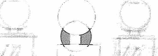
Torque and moment arc vector quantities. The magnitude of the tonlue Of rnoment of a force about a point is equal to the mannitude of the force times the length of the shortc:t distance between the point and the line of action of the force which is known as the lever or moment arm.
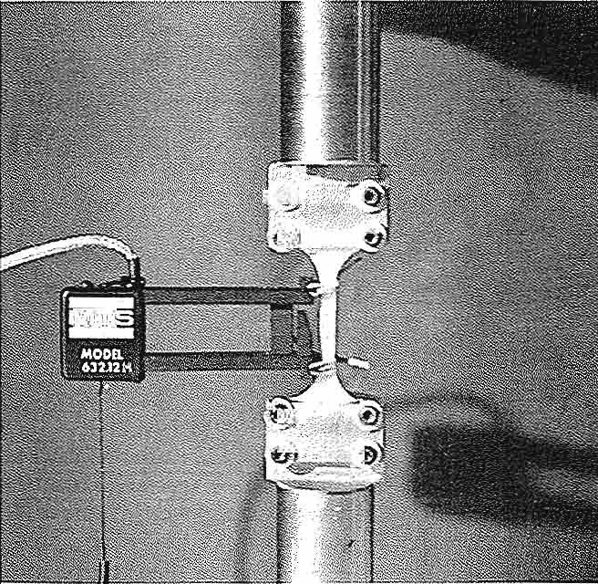
Definition of torque. Reprinred with permission from DZkaya, N. (998). Biomechanics. In w.N. Rom, Environmental and Occupationa( Medicine (3rd ed., pp, New York: Lippincott·Raven,
sider a person on an exercise apparatLls who is holding a handle that is attached to a cable (Fig. I-I), The cable is wrapped around a pulley and attached to a weight pan. The weight in the \veight pan stretches the cable such that the magnitude F of the tensile force in the cable is equal 10 thc weight of the weight pan. This force is transmitted to the person's hand through the handle, At this instant, if the cable allached to the handle makes an angle 0 with the horizontal. then the force E exerted by the cable on the person's hand also makes an angle 0 with the horizontal. Let 0 be a point on the axis of rolation of the elbow joint. To dctermine the magnitude of the moment due to force f about 0, extend the line of action of force f and drop a line from 0 that cuts the line of action of F at right angles. If the point of intersection or the twO lines is Q, then the dbtance d between 0 and Q is the lever arm, and thc magnitude of the ment M of force E about the clbow joint is M = dE The direction of the moment ,·cctor is perpendicular to thc plane defined by the line of action of E and line 00, or for thb two-dimensional case, it is counterclockwise.
NEWTON'S LAWS
Relatively few basic laws govern the relationship betwcen applied forces and corresponding motions, Among these, the laws of mechanics introduced by Sir Isaac Newton (1642-1727) are the most important. NeWLOn's first law states that an object at rest will remain at rest 01' an object in motion will move in a straight line with constant velocity if the net force acting on the object is zero. Newton's second law states that an object with a nonzero net force acting on it will accelerate in the direction of the net force and that the magnitude of the acceleration will be proportional to the magnitude of the net force. Newton's sccond law can be formulated as E = m ;), Here, E is the applied force. m is the mass of the object, and i! is the linear (translational) accelcration of the object on which the force is applied. If more than one force is acting on the object. then E represcnts the net or the resultant force (the vector sum of all forces), Another way of stating Newton's second law of motion is M = I Q., where M is the net or resultant moment of all forces acting on the objcct, I is thc mass moment of inertia of the object, and is the angular (rota- , tional) acceleration of the object. The mass m and mass moment of incrtia I in these equations of motion arc measures of resistance to changes in 1110-
lion. larger the inertia of an object, the more difficult it is to sel if it is rend)' in motion.
Newlon's third law states that to every action there is a reaction and that the forces of action and reaction between interacting objects are equal magnitude, oppositc in direction, and have same line of action. This law has important applications in constructing free· body diagrams.
FREE· BODY DIAGRAMS
Free-body diagrams are constructed to help identify the forces and moments acting on individual parts of a system and to ensure the correct use of equations of mechanics La analyze the system. this purpose. the parts constituting a system are lated from their surroundings and the effects of surroundings arc replaced by proper forces and moments.
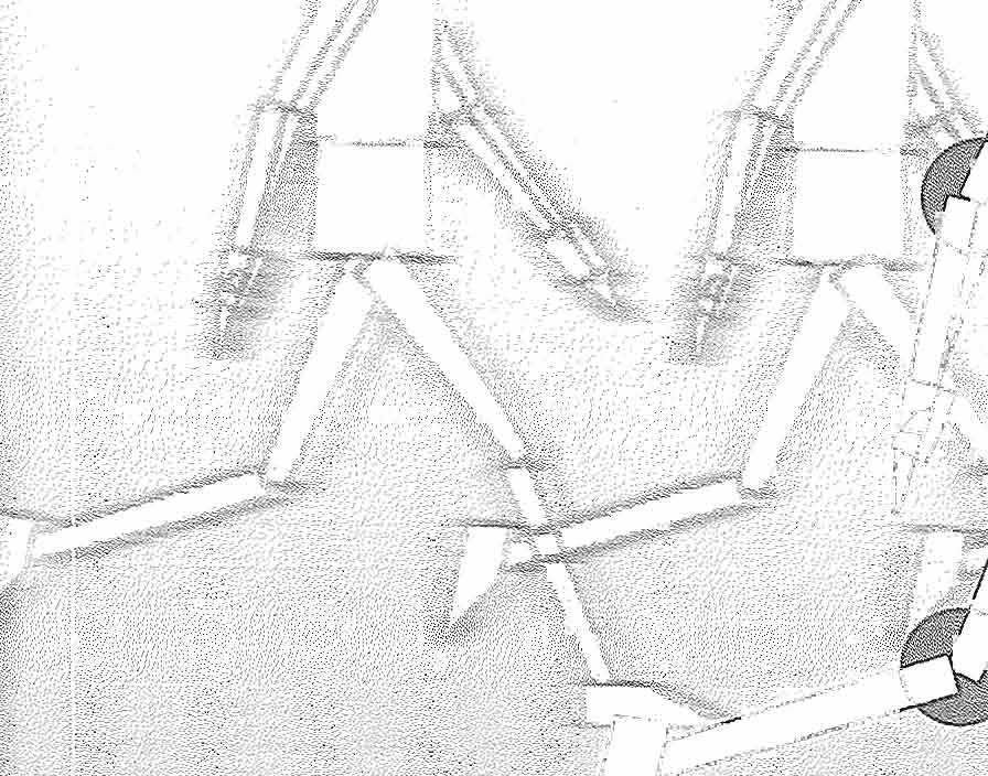
The human musculoskeletal system consists many parts that are connected to one another through a cornplcx tendon. Iigamcnt, muscle, and joint SU·uctUfC. In somc analyses, the objective may be to investigate the forces involved at and around val'ious joints of the human body for different postural and load conditions. Such analyses can be carried out by separating the body into two parts althe joint of interest and drawing the free-body diagram of one of the parts. For example, consider the arn1 illustrated ill Figure I Assume thal the forces volved at the elbow joint arc to be analyzed. As lustrated in Figure 1-2, lhe entire body is separated into two at the elbow joint and the free-body diagram of the forearm is drawn (Fig. 1-2B). Here,
E is the force applied to the hand by the handle the cable attached to the weight in the weight pan, \V is the total wcight of thc lower arm acting the center of gravity of the lower arm,
£,\\1 is the force excrted by' the biceps on the dius,
£.,,; is the force exerted bv the brachioradialis muscles on the radius.
is the force exerted by the brachialis musclcs on the ulna, and
f1 is the resultarll reaction force at the humeroulnar and humeroradial joints of the elbow. Note that the muscle and joint reaction forces represent the mechanical effects of the upper ann on lower arm. Also note that as illustrated in Figure 1-2;\ (which is not a complete free-body diagram). equal magnitudc but opposite muscle and joint action forces act on the upper arm as wcll.
Forces involved at and around the elbow joint and the free-body diagram of the lower arm. Reprinted with permission from dzkaya. N. (7998). Biomechanics. In W.N. Rom, Environmental and Occupational Medicine (31d ed., pp. 1437-1454). New York: Lippincott-Raven.
CONDITIONS FOR EQUILIBRIUM
Statics is an area within applied mechanics that is concerned with the of forces on rigid bodies in equilibrium. A rigid body is one that is assumed to undergo no deformations. [n reality, evcr)' object or matcrial may undergo deformat ion to an extent when acted on by forces. (n some cases, the amount of deformation may be so smalllhal il may not affect the desired analysis and the object is assumed to be rigid. In mechanics, the term cquilib-
dum implies that the body of concern is either at rest or moving with constant velocity. For a body to be in a slate of equilibrium, it has to be both in translational and rotational cquilibl-iul11. A body is in translational cquilibriun1 if the net force (vector sum of all forces) acting on it is zero. If the Ilt:t force is zero, then the linear acceleration (time rate of change of linear velocity) of the body is zero, or the linear velocity of the bod,Y is either constant or zero. A body is in rotational equilibrium if the net moment (vector sum of the moments of all forces) act· ing on it is zero. If the net moment is zero, then the angular acceleration (time rate of change of angular velocity) of the body is zero, or the angulal· yelocily of the body is either constant or zero. Therefore, for a body in a state of equilibrium, the equations of motion (Newton's second law) take the following special forms:
= 0 and = 0
rt is important to remember that force and moment arc vector quantities. For example, with respect to a rectangular (Cartesian) coordinate system, force and moment vectors may have components in the .'\. y, and z directions. Therefore, if the net force acting on an object is zero, then the sum of forces acting in each direction must be equal lo zero (IF, = 0, IF, = 0, IF, = 0). Similarly, if the net moment on an object is zero. then the sum of moments in each direction must also be equal to zero (lM, = 0, lM,. = 0, lM, = 0). Thel'efore, for three-dimension force systems there arc six cOl1ciilions of equilibrium. For two-dimensional force sys[ems in lhe xy-plane, three of these conditions (IF, = 0, = 0, and = 0) need to be checked.
STATICS
The principles of slatics (equations of equilibrium) can be applied to investigate the muscle and joint forces involved at and around the joints for various postural positions of the human body and its segments. The immediate purpose of static analysis is to provide answers to questions such as: What tension must the neck extensor muscles exert on the head to support the head in a specined position? \OVhen a person bends, what would be the force ertcd by the erector spinae on the fifth lumbar vertebra? Ho\\'" does the con1pression at the elbow, knee, and ankle joints vmy with externally applied forces and with different segmental arrangements? How docs the force on the femoral head vary with loads carried in the hand? \,Vhat arc the forces
volved in various muscle groups and joints during different exercise conditions?
In general. the unknowns in static problems involving the musculoskeletal s:'stcm arc thc magnitudes of joint reaction forces and muscle tensions. The mechanical analysis of a skelclal joint requires that we know the vector characteristics of tensions in the muscles, the proper locations of muscle attachments, the weights of body segmcnts, and the locations of the centers of gravity of the body segmems. Mechanical models are obviously simple representations of c0l11plex systems. Many models are limited by the assumptions that must be made to reduce the system under considcration to a st.atically determinate one. Anv model can be improved by the comril)utions of other muscles, but(hat will increase the number of unknowns and make the model a statically indeterminate one. To analyze the improved model. the researcher would need additional information related to the muscle forces. This inforrrlalion can be gathered through electromyography measurements of muscle signals or by applying certain optirnization techniques. A similar analysis can be made to investigate forces involved at and around other major joints of the musculoskeletal system.
MODES OF DEFORMATION
When acted on by externally applied forces. objects may translate in the direction of the net force and rotate in the direction of the net torque acting on them. If an object is subjected to externally applied forces but is in stalic equilibrium. then it is most likely that there is some local shape change within the objec!. Local shape change under the effect of applied forces is known as deformation. The extent of deformation an object may undergo depends on many' factors, including the material properties. size, and shape of the object; environmental factors such as heat and humidity; and the nlagnitudc, direction, and duration of applied forces.
One way of distinguishing forces is by observing their tendencv to deform the object they are applied upon. For example. the object is said to be in tension if the body tends to elongate and in compression if it tends to shrink in the direction of the applied forces. Shear loading differs from tension and compression in that it is caused b:! forces acting in directions tangent to the area resisting the forces causing shear, whereas both tension and compression are caused by collinear forces applied perpendicular to the areas on which they act. It is common
to call tensile and compressive forces normal or ial forces: shearing forces. jects also deform when they are subjecled to forces that cause bending and torsion, which are related the moment and torque actions of applied forces.
A matel"ial nwv respond differently to different loading configurations. For a given material. may be different physical properties that must considered while analyzing the response of that terial to tensile loading as compared with compressive or sheai' loading, The mechanical properties mnterials are established through stress analysis subjecting them to various experiments such as axial tension and compression, torsion, and ing tests.
NORMAL AND SHEAR STRESSES
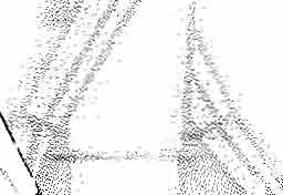
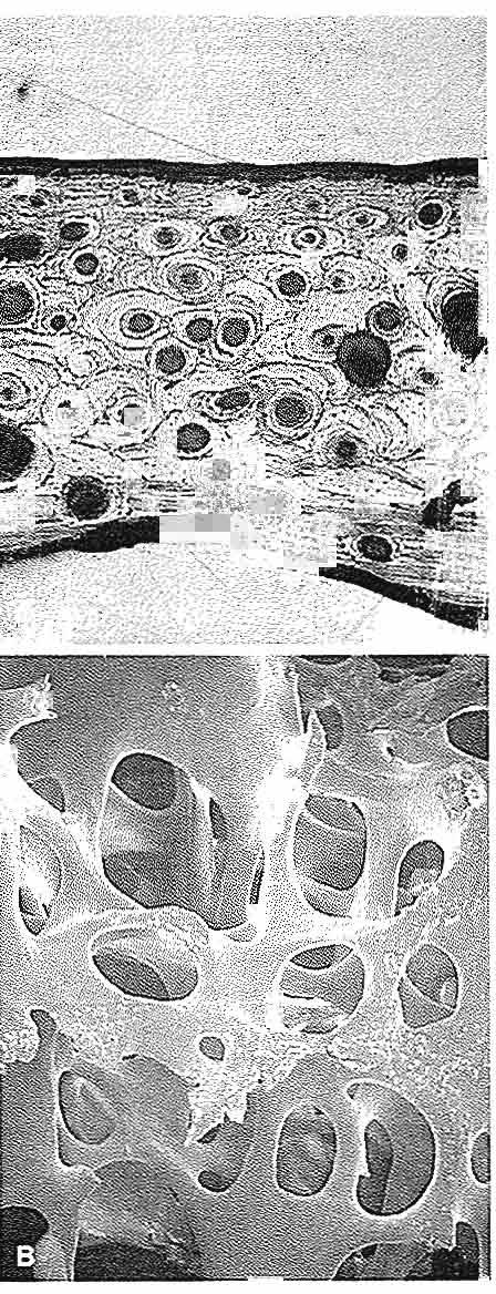
Consider the whole bone in Figure \-3;,\ that is jected to a pair of tensile forces of magnitude F. bone is in static equilibriulll. To analyze the forces induced within the bone, the method of sections be applied by hypothetically cutting the bone two pieces through a plane perpendicular to the axis or the bone. Because the bone as a whole equilibrium, the two pieces must individually equilibrium as well. This requires that at the cut tion of each piece there is an internal force that equal in magnitude but opposite in direction externally applied force (Fig. 1-38). The internal force is distributed over the entire cross-sectional area of the cut section. and E represents the resultant of the distributed force (Fig. 1-3C). The intensity this distributed force (force per unit area) is known as stress. For the case shown in Figure 1-3. because the force resultant at the cut section is perpendicular to the plane of the cut. the cOITesponciing stress called a normal or axial stress. It is customar:y the symbol (T (sigma) to refer to normal stresses. suming that the intensity of the distributed force the Cllt section is uniform over the cross-sectional area A of the bone, then u::::: FlA. Normal stresses are caused by forces that tend to stretch (elongate) matcl"ials aJ"C marc specincally known as tensile stresses; those that tend to shrink them are known compressive stresses. According to the Standard ternational (SO unit system (see Appendix), stresses are measured in newton per square meter which is also known as pascal (Pa). There is another form of stress, shear stress, which is a measure of the intensity of internal forces acting tangent (parallel) to a plane of cut.
d; !:
Definition of normal stress. Reprinted wirh permission from OZkaya. N. (1998j. Biomechanics. In W.N. Rom, Environmental and Occupatiol1<11 r..,ledicine (3rd ed., pp. i437-145r+). New York: Lippincorr·RiNen.
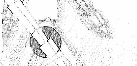
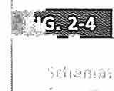
example. consider the whole bone in Figure 1-4A. The bone is subject to a number of parallel forces that act in planes perpendicular to t he long a,is of the bone. Assume that the bone is cut into two parts through a plane perpendicular to the long axis of the bone (Fig. 1-48). If the bone as a whole is in equilibrium, its individual parts must be in equilibrillm as well. This requires that there must be an internal force at the cut section that ,lets in a direction tangent to the cut surFace. If the magnitudes of the external forces arc known, then the magnitude F of the internal force can be calculated by considering the translational and rotational equilibrium of onc of the parts constituting the bone. The intensity of the internal force tangent to the Clit section is known as the shear stress. It is customary to usc the symbol T (tau) to refer to shear stresses (Fig. 1-4C).
Assuming that the intensity of the force tangent to the cut section is uniform over the cross-sectional area A of the bone, then T = FlA.
NORMAL AND SHEAR STRAINS
Strain is a measure of the degree of deformation. As in the case of stress, two types of strains can be distinguished. A strain is deflnecl as the ratio of the change (increase or decrease) in length to the original (undeformed) length, and is commonly denoted with the symbol € (epsilon). Consider the whole bone in Figure \-5. The total length of the bone is I. If the bone is subjected to a pair of tensile forces. the length of the -bone may increase to I' or by an amount .1i\ = I' -I. The normal strain is the ratio of the amount of elongation to the original
Definition of shear stress. Reprintecl with permission {rom Ozkaya, N, (I 99B). Biomechanics. /11 W.N. Rom, Environmenlal and Occupational Medicine (3rd ed" pp. 1437-/454). New York: LippincorrRaven.
Ilength, or E = c,11 1. If the length of the bone increases in the direction in which the strain is calculated. then the strain is tensile and positive. If the length of the bone decreases in the direction in which the strain is calculated, then the strain is compressive and negative.
Shear strains are related to distortions caused shear stresses and arc denoted with the symbol y (gamma). Consider the rectangle (ABCD) shown in Figure 1-6 thm is acted on by a pair of tangential forces that deform the rectangle into a parallelogram (AB'C '0). 'If the relative horizontal displacement of the top and the bOllom of the rectangle is d and the height of the rectangle is then the average shear strain is the ratio of d and which is equal to the tangent of angle y. The angle is vcry small. For small angles. the tangent of the angle is approximately equal to the angle self measured in radians. Therefore, the average shear strain is "y = cllh.
Strains arc calculated by dividing two quantities measured in units of length. For most applications, the deformations and consequently the strains volved may be very small (c,g" 0,001), Strains can also be gi\'en in percemages (e.g O.l%).
STRESS-STRAIN DIAGRAMS
Different I11mcrials may demonstrate different stress-strain relationships. the stressstrain diagrarn shown in Figure 1-7. There arc distinct points on the curve, which arc labeled as P, E, Y, U, and R. Point 0 is the origin of the Sli'essstrain diagram, which corresponds to the initial (no load, no deformation) state. Point P represents proportionality limit. Between 0 and P. stress and strain are linearly proportional and the stressstrain diagram is a straight line. Point E represents the clastic limit. Point Y is the .\"ield point, and stress (T corresponding to the yield point is called the yield slrength of the material. At this Slress level, considerable elongation (yielding) can occur without a corresponding increase of load. U is highest stress point on the stress-strain diagram. The stress (rll is the ultimate strength of the material. The last point on the stress-strain diagram is \vhich represents the nq)ture or failure poinl. The stress at which lhe failure occurs is called the rupture strength of the material. For some materials, may not be easy to distinguish the elastic limit and the yield point. The yield strength of sLieh materials is determined by the offset method, which is applied b.y drawing a line parallel to the linear section of the stress-strain diagram that passes through strain level or approximately 0.2 % The intersection of this line with the stress-strain ClWVC is taken be the vielel point, and the stress corresponding this po-int is called the yield strength the material.
Definition of normal strain. Reprinted with permission from 6zkaya. N. (/998). Biomechanics. In W.N. Rom, Environmental (1nd Occupational !v1edione (lrd ed., pp. /437-1454). New York:
Note that a given material may behave ently under different load and environmental ditions. If the curve shown in F'igurc represents the stress"strain relationship for a material under tensile loading, there ma).o' be a similar but different curve representing the stress-strain relationship for the same material under compressive or shear loading. Also. temperature is known 10411leI' the relationship between stress and strain. For some materials, the stress-strain relationship may also depend on the rate at which the load is applied on the material.
Definition of shear strain. Reprinted wirh permission from OZkaya, N. (1998). Biomechanics. In W.N. Rom, Environmental and Occupational Medicine (3rd ed pp. /437-1454). New York: Lippincou-Raven.
ELASTIC AND PLASTIC DEFORMATIONS
Elasticit:-.· is defined as lhe ability or a material to resume its original (stress-free) size and shape on removal of applied loads. 1n other words, if a load
Stress-strain diagrams. Reprinted with permission from Ozkaya, N. (1998). Biomechanics. In W.N. Rom, Environmental and Occupational Medicine (3rd ed pp. 1437-1454)., New York: LippincouRaven
; is applied on a material such that the Stress generated in the material is equal to or less than elastic limit, the deformations that took place in the material will be cOlllpletcl.v recovered once the applied lands arc removed. An elastic material \vhose stress·strain diagram is a straight line is called a linearly clastic material. For such a matcthe stress is linearly proportional to strain. slope of the stress-strain diagram in the e1asregion is called the elastic or Young's rnodulus of the material. which is commonly denoted by E. ,Therefore, the relationship between stress and strain for linearly elastic materials is a := E€. This equation that relates normal stress and strain is called a material function. For a given material. different material functions may exist for different modes or derormation. For example, SOme materials may exhibit linearly elastic belHwior under shear loading. For such materials, the shear stress T is linearly proportional to the shear strain y, and the constant of proportionality is called the shear modulus, or the modulus of rigidity. If G represents the modulus of rigidity, then ,. = Gy. Combinations of all possible material functions for a given material form the constitutive equations for that material.
Plnsticity implies permanent deformations. Materials may undergo plastic deformations follo\ving elastic deformations when they are loaded beyond their elastic limits. Consider the stress-strain diagram of a material under tensile loading (Fig.I-7). Assume that the stresses in the specimen arc brought to a level greater than the yield strength of the material. On removal of lhe applied load. lhe material will recover the elastic deformation that had taken place by following an unloading path parallel to the initial linearly elastic region. The point where this path cuts the strain axis is called the plastic strain. which signifies the extent of nent (unrecoverable) shape change that has taken place in the material.
Viscoelasticity is the characteristic of a material that has both fluid and solid properties. Most materials arc classified as eilher fluid or solid. A solid material will deform to a ccrLain extent when an exlernal force is applied. A continuously applied force on a Ouid body will cause a continuous deformation (also known as flow). Viscosity is n fluid property thut is a quantitative measure of rcsis· tance to flow. Viscoelasticity is an example of how areas in applied mechanics can overlap, because it ulilizes the principles of both fluid and solid mechanics.
linearly elastic material behavior. Reprinted wirh permission from OZkclycl, N. (1998)_ Biomecll<lflics. In W.N. Rom. Environmental and Occupattonal MecHcme (3rd cd., pp J437-1Li54.J. Ne ,; York: LippincottRaven
VISCOELASTICITY
\·Vhcn they are subjected to relatively low stress els, many materials such as metals exhibit elastic material behavior. They undergo plastic deformations at high stress levels. Elastic materials deform instantaneously when they are subjected to externally applied loads and resume their original shapes almost instantly when the applied loads are mo\·cd. For an elastic material, stress is a function strain only, and the strcss-strain relationship unique (Fig. 1-8). Elastic materials clo not exhibit time-dependent behavior. A different gl'OUp of materials, such as polymer plastics, metals at high temperatures, and almost all biological materials, hibits gradual deformation and recovery when subjected to loading: and unloading. Such materials are called viscoelastic. The response of viscoelastic materials is dependent on how quickly (he load applied or removed. The extent of deformation viscoelastic materials undergo is dependent all rate at which the deformation-causing loads are plied. The stress-strain relationship for a viscoelastic material is not unique but is a f1.lI1ction of time or rate at which the stresse.s and strains are developed in the material (Fig. 1·9). The word "viscoelastic" made of two words, Viscosity is a fluid property
rIncreasing suain rale Ii)
Strain viscoelastic material behavior. Reprinted with permission /rom 6zkaya. N. (1998). Biomedlc1llic5. In WN. Rom, Environmental and Occupational Medicine (3rd ed., P.o. 1.137-/454). New York: Lippincorr·Raven.
is a measure of resistance to now. Elasticity is" solid material property. Therefore, viscoelastic materials possess both nuid- and solid-like properties.
For an elastic material, the energy supplied to deform the material (strain energy) is stored in the material as potential energy. This energy is available to return the material to its original (unstressed) size and shape once the applied load is removed. The loading and unloading paths for an elastic material coincide. indicating no loss of energy. Most elastic materials exhibit plastic behavior at high stress levels. For e1asto-plastic materials, some of the strain energy is dissipated as heat during plastic defat-mat ions. For viscoelastic materials, some or the strain energy is stored in the material as potential energy and some of it is dissipated as heat regardless of whether the stress levels are small or large. Because viscoelastic materials exhibit lime-dependent material behavior. the differences between elastic and viscoelastic material responses are most evident under time-dependent loading conditions.
Several experimental techniques have been designed to analyze the time-dependent aspects of material behaviOl: As illustrated in Figure 1-1004, a creep and recovery test is conducted by applying a load on the matcl¥ial, maintaining the loael at a constant level for a while, suddenly removing the load, and obsen;jng the material response. Under a creep and recovery test. an elastic material will respond
with an instantaneous strain that would remain at a constant level until the load is removed (Fig. I-lOB). At the instant when the load is removecl, the deformation will instantl)' and completely recover. To the same constant loading condition, a viscoelastic material will respond with a strain increasing and ciCCI-casing graduall)r. If the material is viscoelastic solid, the recovery will eventually be complete (Fig. 1-.1 DC). If the material is viscoelastic fluid, complete recovery will never be achicved and there will be a residuc of defOl'mation lerr in the material (Fig. 1-IOD). As illustrated in Figure l-11A, a stress·relaxation experiment is conducted
Creep and recovery test. Reprinred wirh permission from Ozkay,l, N. (1998). Biomechanics. In W.N. Rom, Environmental and Occupational Medicine (3rd ed., pp. 1437-745/1). New York: LippincorrRaven.
'by straining the Olalcriallo a level and maintaining the constant strain while observing the stress response of the material. Under a stress-relaxation lcst, an elastic mater-ial will respond with a stress developed insw.ndy and maintained at a consWnl level (Fig. I-II B). That is, an elastic malcrial will not exhibit a stress-relaxation behavior. t\ viscoelaslie material. conversely', will respond with an initial high stress level that will decrease over time. If the m;terial is a viscoelastic solid, the stress level will nevcr rcduce to zcro (Fig, I-lie), As illuSlrated in Fiourc I-II D, the stress will evct11uallv reduce to o zero for a viscoelastic nuid.
MATERIAL PROPERTIES BASED ON STRESS-STRAIN DIAGRAMS
The stress-strain diagrams of two or Il"wrc materials can be compared to determine \vhich m<:ucrial atively stiffer, tougher, more ductile, or more brittle. For example, the slope of the stress-strain agram in the clastic region represents the clastic modulus that is a measure of the relative stiffness of materials. The higher the elastic modulus, the stiffer the material and the higher its resistance to deformation. A ductile material is one that exhibits a large plastic deformation prior to failure. A britlie material, such as glass, shows a sudden failure (rupture) without undergoing a considerable plastic deformation. Toughness is a measure of the capacity of a material to sustain permanent defonllation. The toughness of a matedal is measured considering the total area under its stress-strain diagram. The larger this area, the tougher the malerial. The ability of a material to store or absorb energy without permanent deformation is called lhe resilience of the material. The resilience of a material is measured by its modulus of resilience, which. is equal to the area under the stress-strain curve in the elastic region. Although thcy arc not directl\' rclated to the stress-strain diagrams, other important concepls are used to describe material properties. For pie, a material is called homogeneous if its properties do not vary from location to location within the material. A material is called isotropic if its properlies are independent of direction. A material is called incompressible if it has a constant denSity.
PRINCIPAL STRESSES
There are infinitely many possibilities of constructing elements around a given point wilhin a structure. Among these possibilities, there may be
Stress-relaxation experiment. Reprinted with permission from Ozkaya, N. (1998). Biomechanics. In WN. Rom. Environmental and Occupational Medicine (Jrd ed.• P.o. 1437-1454). York: Lippincott-Raven.
one: element for which the normal stresses maximum and minimum. These maxin1lrm minimum normal stresses arc called the principal stresses, and the planes whose normals are in directions of the maximum and minimum stJ"esses are called the principal plancs, On a principal plane, (he normal stress is either maximum minimum. and the sheal" stress is zero. It is known that fracture or material failure occurs along planes of maximum stresses, and structures must be designed by taking into consideration the max/ imulll stresses involved. Failure by yielding cessive deformation) n.lay occur whenever largest principal stress is equal to the yield strength of the material or failure by rupture may
occur whenever the largest principal stress ,is ultimate strength of the material. For a given structure and loading condition. the principal stresses be within the limits of operational safely. However, the structure must also be checked for critical shearing stress. called the maximum shear stress. The maximum shear SlI-es$ occurs on a material element for which the normal stresses are equal.
Principal and maximum shear stresses are useful in predicting the response of materials (0 static loading configurations. Loads that Illay not cause the failure of a structure in a single application may cause fracture when applied repeatedly. Failure may occur aher a few or many cycles of loading and unloading, depending on factors such as the amplitude of the applied load, mechanical properties of the material, sIze of the structlire, and operational conditions. Fracture resulting from repeated loading is called fatigue.
Several experimental techniques have been developed to understand the fatIgue behavior of materials. Consider the bar shown in Figure 1-12;:1. Assume that the bar is made of a material whose ultimate strength is U'w This bar is first stressed to a mean stress level (1m and then subjected to a stress fluctuating over time, sometimes tensile and other times compressive (Fig. 1-128). The amplitude (T:, of the stress is such that the bar is subjected to a maxImum tensile stress less than the ultimate strength of the material. This reo versible and periodic stress is applied until the bar fractures and the number of cycles N to fracture is recorded. This experiment is repeated all specimens having the same material properties by applying stresses or varying amplitude. A typical result of a fatigue test is plotted in Figure 1-12C on a diagram showing stress amplitude versus numbct· of cycles to failure. For a given N. the corresponding stress value is called the fatigue strength of the material at that nun1ber of cycles. For a given stress level, N represents the fatigue life of the material. For some matel"ials, the stress amplitude versus number or cycles curve levels off. The stress CT, at which the fatigue curve levels off is called the endurance limit of the material. Below the endurance limit, the material has a high probability of not failing in fatigue, regardless of how many cycles of stress are imposed on the material.
Fatigue and endurance. Reprinred with permission from Olkaya, N. (1998). Biomechanics. In W.N. Rom, Environmeniat and Occupational Medicine (3rd ed., pp. 1437-1454). New York: Lippincou-Raven.
The fatiguc behavior or a material depends on several factors. The higher the temperature in which the material is used, thc lower the fatigue strength. The fatigue behavior is sensitive to surface imperfections nnd the presence of discontinuities within the material that can cause stress concentrations. The fatigue failure starts \vith the creation of a small crack on the surface of the material. which can propagate under the effect of repeated loads, resulting in [he rupture of [he material.
Orlhopaedic devices lII)dergo repeated loading and unloading as a result of the activities of the patients and the actions of their 111uscles. Over a pe-
riod of vears. a weight-bearing prosthetic dc\·icc or a' device can be subjected to a consiclerabk number of cycles of stress reversals as a result or noHnal daily activity. This cyclic loading and un.• l;"N can cause faLigue failure of the device.
Biomechanics the Musculoskeletal System
even a simple task c.'\ecuted b.v the musculoskeletal svstcm requires a broad. in-depth knowledge of various fields that include 1110tor control, neurophysiology, physiology. physics. and biomechanics. For example, based on the purpose ancl intention or a task and the information gathered from the cndronmcnl and orielllatioll of tilL' body and joints, the central nervous system plans a strategy for a task execu:;.: lion. According to the strategy adoptc:d. Illuscles / .. ' .,' will be recruited lO provide Lh<..' forces and 1110mcnts required for the movement and I.Jalance of the s.)'slem. Consequently, the internal forces will be changed and soft tissues will experience different load conditions.
The purpose or this book is to present a balanced synthesis of information gatllCred frorn various disciplines. pro\'iding a basic understanding of biomechanics of the musculoskeletal system. The material presented here is organized (0 cover three areas of musculoskeletal biomechanics.
PART I: BIOMECHANICS OF TISSUES AND STRUCTURES
The material presented throughout this textbook provides an introduction to basic biolllechanics of the musculoskeletal system. Part I includes chapters on the biomechanics of bone. articular cartilage, tendons and ligaments, periphcral nerves, and skeletal muscle. These are augmcnted wilh case studies to illustrate the imponarll concepts for understanding the biomechanics of biological tissues.
PART II: BIOMECHANICS OF JOINTS
Part II of this textbook covers the major joiots of the human body, from the spine to the ankle. Each chapter contains information about the structure and functioning of the joint. along with case studies illuminating the clinical and management of joint injlll)' and illness. The chnpters are written
clinicians (Q provide an
knowh:dge about
PART III: APPLIED BIOMECHANICS
A new section in the third edition of this book troduces important issues in applied biomechanics. These include the biomechanics of fracture fixation; arlhroplasty; sitting, standing. and lying; and gait. is important for the beginning studenl to understand the application or biomechanical principles clirfcrcnt clinical areas.
Summarv
1 Biomechanics is a young and dynamic fidd study based on the recognition thaI conventional cllginccl'ing thcorks and methods can be useful understanding and solving problems in physiology and medicine. Biomcclwnics considers the applications of classical rncchanics to biological problems. The flcld of biomechanil:s flourishes from the cooperation among life scientists, physicians, engineers. and basic scientists. Such cooperation requires certain amount of common vocabulary: an engineer must learn some and ph)'siology, nnclmedical personnel need to understand some basic concepts of physics and mathematics.
2 The information presented throughout this textbook is drawn from a large scholarship. The thors aim to introduce some of the basic concepts biolllechanics related to biological tissues and joints. The book does nOl intend to provide a comprehensive review of the literature, and readers encouraged to consult the list of suggcsted reading below to supplcmcnt theil' knowledge. Some basic textbooks arc listed here, and studcnts should consult peer-revicwed journals for in-depth presentaLions of the latest research in specialty arcas,
SUGGESTED READING
Black. J. (19SS). Onhop'lcdic Bionmleriuls in R,'sl,.'ardl and Practil:c. New York: Churchill Li\·in!!stonc. Brollzino. J.D. (Ed.) (1995). The -Biom(.'dic<ll Engincl.'ring H.lIld* book. 80(:01 R:llOn. rL: CRC Press. B(lrst('in, A.H., & \Vright. 1993). Fundamellt;lls of Or1hop<ll'dic Biolllc:dmnics. Ballirnorl': Williams & Wilkins. Chaffin. 0.8 .. & All{krsson. G.B.J. (1991). O<::cupational Bioll1c(2nd l'<'I.). Nl'\\' York: John Wiley & Sons. Fung. Y.c. (1981). Biolllec!wnics: Mechanical Properties of Living Tissul.·s. New York: Springl.'r·\\:rJag. FUll!!. yc. (1990). ;\·Iotioll, Flo\\" Slrcss, :llld Growth. New York: Springl'r,Vl'rlOIg.
NahulIl. A.M &. Md\'in. J. (Etls.). (19S5). The BiOlllcch:lI1il:s of TI'UUll'l. Norwalk. CT:
Nordin, M Andersson. G.B.J., & Po\X", M.H. (Eds.). (1997). 1()sk :k'IJI Disonk'J1; in the \VorkpbcL'. Philadclphin: :\'1osby,Ycilr Book.
Nordin. & Franb,:1. \l.H. (Eds.l. (1989). Basit- OiolUl.'chanics of lhe :\hlst.:uloskdctal S,\':o;'lClll (2nd t:d,), Philaddphi:l: 1...:<.\ & F.:bi"'.:r
OzkaYil,eN.·( 1998). III W.N. Rom, EnvirorH1H:nlal and OCCllp<:lliollal Ord cd., pp. 1437-1454). New York: Li ppi m:olt -RaVCll.
OZk:IY;\. N & Nordin. M. (1999). Fundamelltals of
Equilihrium, :\lotioll. <lnd Dcfonlwtioll (2nd I..'d,). Nt:\\" York
Schmid.Schonbl'i;l, G.\\'., \\'00. 5.1...·) & Z\\"eifach. B.\V. (Eds.). (1985). Frontiers in Biomechanics. York: Springer.Verlag:, Skal<:lk, R" & Chkn, S. (Eds.). (!98i). Hllndbonk or BiOi..'ngincering. New York: McGraw·Hill. Thompsoll. C. W. (1989). :\·tanu'll of Stlllt'lur<ll (11th cd,). 51. Louis. MO: ·fill1l..'s Mirror/:\·Iosbv. Williams. M., & lissner, H.R. (1992). Bion;l.'chanics of !·luman ;\'tolion (3r<l cd.). Phibddphin: Sallll(k:rs, Wintcl'. D.!\. (1990). Biol1lcchnnics :Illd Control or Hum"n Behavior (2nd I..'d.). New York: John Wiky &: Sons. Willlel'S. J,!lil.. &. Woo. S.L-Y. (Eds.), (1990). Multiple Muscle SysIl'IHS. New York: Springcr.verktg.
The System International d'Unites (51)
The 51 Metric System
Base Units
Supplementary Units Derived UnitS
Specially Named Units
Standard Units Named for Scientists
Converting to 51 From Other Units of Measurement
Dennis R. Carter
The''S! Metric System
,,;The System Intemational d'Unites (SI), the metric system, has evolved into the most exacting system of 'measures devised. In this section. the 51 units of lllcasurcmcnl used in the science of mechanics arc described. SI units used in electrical and light sciences have been omitted for the sake or simplicity.
BASE UNITS
The 51 units can be considered in three groups: I, tbe base units; 2. the supplementary unils; and 3. the derived units (Fig. App-I). The base units are a small group or standard measurements lhal have been arbitrarilv defined. The base unit for length is '-'rhe meler (Ill), "and the base Llnit for Illass is the kilogram (kg). The base units for time and temperature are the second (s) and the kelvin (Kl. respectively. Definitions 01" the base units have become.:: increas· .ingly sophisticated in response to the expanding needs Hnd capabilities of the scientific community (Table App-I). For example, the meter is now de-
QUANTITIES EXPRESSED IN TERMS OF UNITS FROM WHICH THEY WERE DERIVED
fined in terms of the of radiation emitted from the krvpton-S6 atom.
SUPPLEMENTARY UNITS
The radian (rad) is a supplemental)' unit (() measure plane angles. This unit, like the base units, is arbitrarily defined (Table App-I). Although the radian is the 51 unit for plane angle. the unit of the degree has been retained for general use because il is firmly established and is widely Ltscd "round the world. A degree is equinllcnl to rrll80 rad.
DERIVED UNITS
ivlostunits of the 51 system are derived unils, meaning lhat they- are established from the base units in accordance with fundamcntnl physical principles. Some of these units are in terms of the base units from which they are derived. Examples aloe area, speed, and acceleration. which arc expressed in the Sf units or square meters meters per second (m/s), and meters pCI' second squared (In/s 2), respectively.
DERIVED UNITS WITH SPECIAL NAMES
& STRESS pascal N/m 2 MOMENT OF FOACE FORCE new Ion kg m/s 2
ACCELERATION qp ,----....
The International System of Units.
& WORK joule Nm
Specially Nanzeel Units
Other dedved units are similarl.v established from the base units but have been given special names (Fig App-I and Table App-I). These units are defined through the lise of fundarnental equations or physical laws in conjunction with the arbitrarily defined Sf base units. For example, Newton's second law of motion states that when a body that is free to Il10vC is subjected to a force. it will experience alion proportional to thai force and inversely proportional to its own mass. i\Jlathcmatically, this principle can be expressed as:
force = Illass X acceleration
The Sf unit of force, the newton (Nl, is lherefore defined in terms of the base SI units as:
1N = 1 kg XI I11/S:!
The Sf unit or pressure and stress is the pascal (Pa). Pressure is defined in hydroslaties as the force divided by the area of force application. Mathem4llthis can be expressed as:
pressure = force/area
I ; Definitions of Sl Units
The 51 unit of pressure, the pascal, is therefore defined in terms of the base 51 units as:
I Pa = IN I I 111"
Allhough the S[ base llnil of temperature is the kc.:lvin, the derived unit of degree Celsius (OC 01' c) is much marc commonly used. The degree Celsius is equivalent to the kelvin in magnitude. but the solute value of the Celsius scale differs frol11 that of the Kelvin scale such that °C = K- 273.15. ,",Vhen the 51 is used in a wide variely of measurements, the quantities expressed in terms of the base. supplemental. or derived units be either very large or very small. For example, the arca on the head of a pin is an extremely small number when expressed in terms of square meters. Conversely, the weight of a whale is an extremely large number when expressed in terms of newtons. To accomrnodate the convenient representation of small or large quantities, a system of prefixes has been incorporated into the SI system (Table App-2), Each prefix has a fixed meaning and can be used with all 5Iunils. \!\Then used with the name or the unit, the prefb: indicates that the quanti!}! described is being expressed in some multiple or
Base 51 Units kilogram (kg)
second (s)
kelvin (k)
Supplementary SI Unit
radian (rad)
Derived SI Units With Special Names
newton (N)
pascal (Pa)
joule (J)
wall (W)
degree Celsius (C)
The meIer is the length eqllal to 1,650,763.73 wavelengths in vacuum of the radiation corresponding to the transition belween the levels 2PHi and Sd" of the krypton-86 atom.
The kilogram is Ihe unit of mass and is equallO the mass of the international proto· type of the kilogram.
The second is the duration of 9.192,631,770 periods of Ihe radiation corresponding to the transition between the two hyperfine levels of the ground state of the cesium-133 atom.
The kelvin. a unit of thermodynamic temperature, is the fraction 1/273.16 of the thermodynamic temperature of the triple point of water.
The radian is the plane angle between two radii of a circle that sub tend on the ference of an arc equal in length to the radills.
The newton is that force \tvhich, when applied to a rpass of 1 kilogram, gives it an aCceleration of 1 meter per second squared. 1 N= 1 kg rn/s /
The pascal is the pressure produced by a force of 1 newton applied. with uniform distribution, over an area of 1 square meter. 1 Pa = 1
The joule is the work done when the point of application of a force of 1 newton is displaced through a of 1 meter in the direction of the force. 1J = 1 Nm.
The watt is the power that in 1 second gives rise to the energy of 1 joule. 1W ::: 1 J/s.
The degree Celsius is a unit of thermodynamic temperature and is equivalent to K273.15.
Factors and Prefixes
SI Prefix SI Symbol
giga G
mega Iv1
kilo k
hecla h
deka da
deci d
centi c
rniJli rn
micro I'
nana n
pica p
Reprinred wirh permission from Ozkaya. N & Nord,-n. M. (1999). Fundamentals oi Blomechani(!>: Equilibrium. Mo· tion. and Deiormatlon (2nd ed.) New York: Springer·lJer/ag. p, iO.
ten times the unit used. For example. the millime· 'tel' (mm) is used to represent one thousandth (10"·1) of a meter and a gigapascal (Gpa) is uscd to denotc one billion (10') pascals.
---_._--------
, SI Units Named After Scientists Symbol Unit
ampere
( coulomb
O( degree celsius
F farad
H henry
Hz hertz
J joule
K kelvin
N newton
fl ohm
Pa pascal
5 siemens
T testa
V volt
W walt
Wb weber
Quantity
electric current
electric charge
temperature
electric capacity
inductive resistance
frequency
energy
temperature force
eleclrlc resistance
pressure/stress
electric conductance
magnetic flux density
electrical potential
power
magnetic flux
Standard Units Nmned for Scientists
One of the more interesting aspects of the SI is its lise of the names of famous scientists as dard units. In each case, the lInit was named scientist in recognition of his contribution Geld in which that unit plays a major role. App-3 lists a number of Slullits and the scientist which each was named.
For example. the unit of force. the neWlon, named in honor of the English scientist Sir Ncwlon (1624-1717). Hc wa' cducalcd 'II College at Cambridge and later rclurned to College as a professor or mathematics. Early career, Newton made fundamental contributions malhcmalics Ihat formcd Ihc basis of diffcrcntial and integral calculus. His other major discoveries were in the fields of optics. astronomy. gravitation. and mechanics. His work in gravitation was portedly spurred by being hit on the head by ple falling from a tree. It is perhaps poetic that the SI unit of one newton is approximately equivalent to the weight of a medium-sized Newton knighted in t 705 by Qucen i\ltary his monumental contributions to science.
Scientist
Country of Birth Oates
Amphere, Andre·tvtarie France 1775-1836
Coulomb, Charles Augustin de France 1736-1806
(elsius. Anders Sweden 1701-1744
Faraday, Michael England 1791-1867
Henry, Joseph United States 1797-1867
Hertz, Heinrich Rudolph Germany 1857-1894
Joule. James Prescott England 1818-1889
Thomson, William (lord Kelvin) England 1824-1907
Newton, Sir Isaac England 1642-1727
Ohm. Georg Simon Germany 1787-1854
Pascal, Blaise France 1623-1662
Siemens, Karl Wilhelm (Sir William) Germany (England) 1823-1883
Testa. Nikola (roatia (US) 1856-1943
Volta, (ount Alessandro Italy 1745-1827
Watt, James Scotland 1736-1819,
Weber, Wilhelm Eduard Germany 1804-189}.;;};'
centimeter (em) = 0.01 meter (01)
1 inch (in) = 0.0254 rn
1 foot (ft) = 0.3048 rn
1 yard (ydl = 0.9144 rn
1 mile = 1609 m
1 angstrom (A) = 10" rn
Time
I minute (min) :::; 60 second (s)
1 hour (h) = 3600 s
1 day (dl = 86400 s
Mass
1 pound mass (1 brn) = 0.4536 (kg)
1 slug ::: 14.59 kg
Force
1 kilogram force (kgf) = 9.807 Nevvton (f\J)
1 pound iorce IIbO = 4448 N
I dyne (elyn) "I0
Pressure and Stress
1 kgl rn·s:' = 1 N/m" = 1 Pascal (Pal
I Ibi / in' (psi) = 6896 Pa
I Ibl / ft' (psO = 92966 Pa
I dyn / em' = O. I Pa
Moment (Torque)
1 dyn-cm = i 0. 7 N-rn
i Ibf-ft = 1.356 N-m
Work and Energy
1 kg-m' / s' = 1 N-m = 1 Joule IJ)
1 dyn-cm = 1 erg = lO-} J
1 Ibi-It = 1.356 J
Power
I kg· rn' / s' = 1 J/s = 1 Watt (1"1)
I horsepower (hpl = 550 Ibl·IVs = 7461"1
Plane Angle
J degree ("') .::;: 1</180 radian (fad)
1 revolution (rev) :=: 360"
1 rev;::: 211: raci -."-' 5.283 rad
Temperature <>( '" 273.2
Reprinted with pefFnisslon from OZkaya. 1'1., & l'1i. (1999). Fundamentals oi Biomechanics: EqUllib· rium. Motion. and DeformatIon (2nd ed.) New York: Spnnger-verlag. p. 11.
The unit of pressure and stress. the pascal. was named after the French physicist, mathematician, and philosopher Blaise Pascal (1623-1662). Pascal conducted important investigations on the <.:harncteristics of vacuums and barometers and also invented a machine that would make mathematical calculations. His work in the area of hydrostatics helped lay the foundation for the later developmenl of these scientific ficlds_ In addition to his scicntific pursuits, Pascal was passionalely interested in religion and philosophy and tllllS wrote extensively on a wide range of subjects.
The base unit of temperature, the kelvin. was named in honor of Lord Vv'illiam Thomson Kelvin (1824-1907). Named William Thomson, he was cd·
ucated at the Universit.\· of Glasgo\\" and at Cambridge University. Early in his career, Thol11son vcstigated the thermal propcnies of steam at a entific laboratory in Paris. At thc age of 32, returned to Glasgo\\" 10 accept the chair of Nalural Philosophy. His meeting with James JOllie in 1847 stimulated interesting discussions on the nature heat, which eventually lecl to the establishment Thomson's absolute scale of temperature, the Kelvin scale. In recognition of Thomson's contributions the field of thermodynamics, King Edward VIl confen-cd on him the title of Lord Kelvin.
The commonly llsed unit of temperature, the gree Celsius, \\ as named aftcr the Swedish lronomcl and lmenlO! Anders CelsiLl' (1701-1744).
Celsius was appointed professor or astronomy at the Inii"p-",i,\' of Uppsala at the age of 29 and remained the university until his death 14 years latec [n 1742, he described the centigrade thermometcl- in a paper prepared for the Swedish Academ!' of SciThe name of the centigrade temperature waS officially changed to Celsius in 1948.
to Sf From Other of'Measurement
Box App·t contains the formulae for the conversion measurements expressed in English and non-Sl units into Sf units. One fundamental source of connJSlon in converting from one system to another is that (wo basic of Illeasun:menl systems exist. In the "ph\'sical" system (such as SI). the units of length. time, and nUlSS arc arbitrarily defined, and other units (including force) are derived fron1 these ,. base units. In "technical" or "gravitational" systems
(slich as the English system). the units of length, time, and force arc and other units (including mass) are derived from these units. Because lhe units of force in gravitational tems are in fact the It'eights of masses. version to 51 is dependent on the acceleration mass due to the Earth's gravity, By' international agreement. the acceleration due to gravity 9.806650 m/s'. This \'aille has been lIseel in establishing some of the conversion factors in Box App-I.
Pennychuick, C.J. {1974l. lIulldy .\!tllrif:l's oj" VI/il Crntl't'n;UIl Pi/oon (or Riolof!..\' amI .\lcclulJI;cs. New York: John Wiley &: \Vorld Health (19i7). The SI /01' t!le fha/til jt's$iol1s. Gl.'llt'\"C WHO.
Biomechanics of Tissue and of the Musculoskeletal System
Biomechanics of Bone
Victor H. Frankel, Margareta Nordin
Introduction
Bone Composition and Structure
Biomechanical Properties of Bone
Biomechanical Behavior of Bone
Bone Behavior Under Various loading Modes
Tension
Compression
Shear
Bending Torsion
Combined l.oading
Influence of Muscle Activity on Stress Distribution in Bone
Strain Rate Dependency in Bone
Fatigue of Bone Under RepetitivE: Loading
!nfluence of Bone Geometry on Biomechanical Behavior
Bone Remodeling
Degenerative Changes in Bone Associated With Aging
Summary
References
Flow Charts
or the skeletal system is to protect inprovide rigid kinematic links and sites, and facilitate Illuscle ac· movement Bone has unique stl·UC· mechanical properties that allow it to these roles. Bone is among the body's onl)' dentin and enamel in the :,:;:::';:,:::':i:, It is one of the most dynamic and ?9Pp'.cally active tissues in the body and re· throughollt life. A vascular tishas an excellent capacity for self-repair and tan its properties and configuration in rc. to changes in mechanical demand. For example, changes in bone arc commonly after pL:riods of disuse and of greatly increased use; changes in bone shapL' are noted dur· iog fracture healing and after certain operations. .;: Thus, bone adapts Lo the mechanical demands placed on i l.
This chapter (iL'scribcs the composition and structure of bone tissue, the mechanical properties of bone, and the behavior or bone under different loading conditions. Various factors that affect the mechanical behavior of bone in vitro and in vivo also are disclissed.
Bone Composition and Structure
Bone tissue is a specialized connective tissue whose solid composition suits it for its supportive and proteclive roles. Like other connective tissues, it con· sisrs of cells and an organic extraccllular matrix of fibers and ground substance produced by the cells. The distinguishing reature of bone is its high con· tent of inorganic materials, ill the form of mineral salts, that combine intimately with the organic matrix (Buckwalter et al., 1995). The inorganic compo· nent of bone makes the tissue hard and rigid, while the organic component bone its flexil)ility and resilience. The composition of bone dirrers depending on site, animal age. dietar:.y histol)', and the pres· ence or disease (Kaplan et aI., 1993).
In normal human bone, the mineral or inorganic portion of bone consists primarily of calcium and phosphate, mainly in the form of small crystals rc· sembling synthetic hydroxyapatite crystals \vith the composition Ca",(PO,)o(OI-l),. These minerals, which for 60 to 70% of ilS dry weight, give bone its solid consistency. "Vatcr nccounts for 5 to SOk and the organic matrix makes tip the J'cmainder
of the tissue. Bone scn·cs <.lS a rcsen/Oir for essential minerals in the particularly calcium. Bone minend is embedded in oriented fibers of the protein collagen, the fibrous ponion of the extracellular matrix-the inorganic matrix. Collagen ribers (type l) are tough and pliable, they resist strelching have lillie L'xtensibility.
CollagL'1l composes 9(YYo of the tracellular matrix and accounts for approximately 25 lO 3W>'r' of the wl'ight of bone. A universal building block of the body, collagen also is chie!" fibrous component of other skddal structures. (A detailed descriplion 01" the microstnlcturc and mechanical behavior of collagen is provided Chapters 3 and 4.)
The gelatinous ground substance slIlTounding thc mineralized collagcn fibers consists mainly protein polysaccharides, or (GAGs), primarily in the form of cOlllplt:x macro· molecules called protcoglycans (PGs). The GAGs as a cementing substance between layers mineralized collagen fibers. GAGs, along wit.h various noncollagcI1ous glycoprotcins, constitute approximately 5% of the extracellular rnatrix.
(The structure or PG:-:, whi,:h arc vital components of artie, i:il' is described in delail in Chap· kr .) 1
\Vater is abundant in live bone. accounting for up to 25% of its total weight. Approximately 85°10 of the walt.'r is found in the organic matrix, around the collagen fibers and ground sllbstance, and in the h.vdl·ation shells surrounding the The other 15% is localed in the canals cavities that house bone cells and carry nutrienls t bone t issuc.
At the microscopic level, the fllndamcmal StI11Clllralunit of bone is the osteon, or haversian system (Fig. 2·1). At the center of each osteon is a small channel, called a haversian canal, lIlat conlains blood vessels and nerVe fibers. The osteon itself sists of a concentric series of layers (lamellae) mineralized rnatrLx surrounding the central canal, configuration similar to growth in a trunk.
Along the bOllndflries of each layel: or lamella, small cavities known as lacunae, each cOl1laining 011(.' bone cell. or ostcocyte (Fig. 2-1 C). Numerous small channels, called canaliculi, radiate from lacuna, connecling the lacunae or adjacent lamellae and ultimately reaching the haversian canal. processes extend from the osteocytes into the canaliculi, allowing nutrients '[Tom the blood vessels in haversian canal to reach the osteocyles.
A. The fine structure of bone is illustrated schematically in a section of the shaft of a long bone depicted without inner marrow. The osteom. or haversian systems. are apparent as the structural units of bone. The haversian canals are in the center of the osteons, which form the main branches of the circulatory network in bone. Each osteon is bounded by a cement line. One osteon is shown extending from the bone (20x). Adapted from Basset!, CAL. (1965). £/ecrrical effects in bone. SCI Am, 213.18. B, Each osteon consists of lamellae. concentric rings composed of a mineral matrix surrounding the •
haversian canal. Adapled irom Torrora G.J.. & Anagnostakas. N.P. (198:1). Principles of Anatomy and Physiology edJ. York: Harper gRow. C, Along the boundaries the lamellae are small cavities known as lacunae, each of which contains a single bone cell, or osteocyte. ating from the lacunae are tiny canals, or canaliculi, into which the cytoplasmic processes of the osteocytes extend. Adapted from Torrora G.; & AOclgflosrak05. N.P. (1984). Principles of AnalOmy and Physiology (4th edJ. York: Harper &
At the pcriphcl)! of each osteon is a cement line, a nrtrrow area of cement-like ground SubSlrtllCe composed primarily of GAGs. The canaliculi of Ihc osteon do not pass this cement line. Like the canaliculi, the collagen fibers in the bOl1e matrix interconnect from one larndla to another within an osteon but do not cross the cement line. This intertwining of collagen fibers within the osteon undoubtedly in-, creases the bone's resistance to mechanical stress and probably explains the cement line is the weakest portion of the bonc's microstructure.
A typical osteon is approximately 200 micronletcrs (J..l) in (lin·rnctcr. Hence, evclY point in the teon is no more than 100 J..llll from the centrally catcd blood supply. In Ihe long bones, the osteons usually run longitudinally. but they branch quelltly and anaslOmose extensively with othcl:
Jnterstitial lamellac span the regions between complete O!"h:ons (Fig: 2-1..1). They arc continuous with the ostcons and consist of the same material a difTerent geol11ctric configuralion. As in the
Frontal longitudinal head. neck, greater trochanter, and proximal shaft of an adult femur. Cancellous bone, with its trabeculae oriented in a lattice, lies within the shell of cortical bone.
Reprinted with permission from Gray, H. (T 985). Anatomy of the Human Body. (73(h American ed.J. Philadelphia: Lea & Febiger.
teons, no point in the interstitiallamellae is farther than 100 JLm from its blood supply. The interfaces between these lamellae contain an alTa)' of lacunae in which oSleocytes lie and from which canaliculi cXlcnd.
!\l the macroscopic level, all ..,!re.. c.Qrnposed of twotvpes, cortical. or compact, bone
COl'tiC,,1 hoi1"Tili'ms the Otlt",:,11-"II:or' cortex: of the has a stt'llct,llre of ivory. bo;;e within is composed or-thin plates. o'j"lrabeclllae, in a loose lhf([rlier'si-i·ccs--bctwe.en the lrabct:ulat:: are filled red ;;all'O\';" (Fig. isaiTangeCi in concentric lacunae-cQn'i"ainTilgJii!l)ellae--ouiclocsn-ot haversian canals. The osteoc:\;tes re'ceive nUlricn-islhrough canaliculi from blood vessels passing through the red marrow. lieal bone always G!.pccl!.ous lJ.one. bUl· thi-rdative quantily of each lype varies' among bones and wilhin individual bones according to funclional requirements.
photomicrograph of cortical from a human tibia (40;<). B, Scanning electron photomicrograph of cancellous bone from a human tibia (30)-:). Reprinted wirh permission from Carrer. D.R., & Nayes, We. (1977). Compact bone fatigue damage. A microscopic aminalion. Clin Onhop, 127, 265.
On a rnicroscopic level, bone consists of .woven and lamellar-bone (Fig. 2-4). Woven bOlle is-con-si(lerecl"immatllre bone. This type or bone is rOll t1 d enlbryo.-in the newborn, in the- fracturc'callus, lhe riietaphysial region of growing bone as well tUIl-lOrS, ostcogcl]csis lmperfecla, and pagctic Lal-nellar bone begins to form 1 month arter birth
activelv replaces woven Lamellar bone is therC'bOlle.---
All bones are §urrounded by a dC.llse membrane called the periosteulll (Fig. 2-1.-\). Its ouler vessels (Fig. 2-5) and nerve fibers that pass into the cortex via Volk,llunn's cH"nalS: eLl m\ls ,I)one .. f\ n i n Ils '" spo"nsible '(or nc\v Gc;'n-c'''du'i-ing ", ,5:_".". .",.. "" •. """ and ,'cRail'. (ostcoblasls). The periosteum covers -b0I1::' except for the - joint-'Slld"a-ces, which m":Cco\;'cr'ccT'witTl arlicufm- cartilage. InThe long borles, 'a- thin'llcr line";; t heee n 1 ral (;;;";;clujIaty j v:,\' Ii fall'; The' endostcum giant l.ioli"-e"lisctlTfec! osteoela-sfs: both of which i m g I'P of bone .
Schematic drawing and photomicrographs of lamellar and woven bone, Adapted from Kaplan, F.5., Hayes, We., Keaveny. T.M., er a/. (1994). Form and funcrion of bone. In S.R. Simon (Ed.). Orthopaedic Basic Science (pp. 129, 130). Rosemonr, fL: AAOS.
Woven
Orthopaedic
Biomechanical Properties of Bone
Biomechanically, bone tissue may be a (biphasic) I1),aterial;" with the mineral as onCjJhase and the collagen and ground substance as_.the In such matcl"'ials (n logic-al exal,'lple is fiberglass) in which a strong. brittle material is embedded in a more Oexible one, the combined substances ;:tre stronger for their weight than is either substance alone (Bassett, 1965),
Functionally, the most important mechanical properties of bone are its strength and stiffness. These and other characteristics can best be understood for bone, or any other structure, by e:'\amining its behavior under .loading, that is, under the innuence of externally applied forces. Loading causes a deformation, or a change in the dimensions, of \·Vhen a load in a known direction is imposed on a structure, the deformation 01" that structure can be rncasurcd and ploued 011 a loaddeformation curve. I\lluch information about the
strength, stiflness, and other mechanical properties of the structure can be gained examining curve.
A hypothetical load-deformation curve for somewhat pliable fibrous structure, such as a long bone, is shown in Figure 2·6, The (straight line) portion of the curve, the c1asticJ'cgion. reveals the elasticity bf the structure, th:u is, its capacity returning io its original shape after the load is moved, As· the load is applied, deformati911 occurs btll is not permanent; th-e structure recovers its original sllape \\'hen unloaded. As loading c·ontinues. outcrni"ost fibers of the struCture begin to yield some point. This yidd poinl signals the elastic limit of the structure, As, the load exceeds this limit, structure exhibits plastic behavior, in second (curved) portion of the eurvc, the p!as,tic gion. The structure no longer return to its origi11al dimensions when the load has been released; some residual deformation will be permanent. loading-is progressively increased, the structure fail at'somc point (bonc' will fracturc), This point by the ultimate failure point on the CUI've,
Adap,ed from FS Nayes, w,e .. rA1 .. et M (1994). Form and function of bone. In 5.R, Simon (Ed.).
Basic Science (p. /3i}. Rosemon£, It: AAOS
Load-deformation curve for a structure composed of a somewhat pliable material. If a load is applied within the elastic range of the structure (A to B on the curve) and is then released, no permanent deformation occurs. If loading is continued past the yield point (B) and into the structure's plastic range (B to C on the curve) and the load is then released, permanent deformation results. The amount of permanent deformation that occurs if the structure is loaded to point 0 in the plastic region and then unloaded is represented by the distance between A and D. If loading continues within the plastic range, an ultimate failure point (C) is reached.
acterizing a bone or other structure in terms of material of \vhich it is composed, independent of geometry, requires standardization of the testing conditions and the size and shape of the test specimens. Such standardized testing is useful for comparing the 111echanical properties of two or more materials, such as the relative strength of bone tendon tissue or the relative stiffness of various terials used in prosthetic implants. More precise units of measurement can be used when standardized samples are tested-that is, the load per unit area of the sample (stress) and the amount of deformation in terms of the percentage of change in sample's dimensions (strain). The curve generated a stress-strain curve.
Stress)s:the load, or force, per unit area that velops on a plane surface within a struc:lll['e.)11 applied loads. The three most commonly used for measuring stress in standardized samples of bone are ne\vtons per centimeter squared (N/cm:;); newtons per meter squared, pascals (N/m 2 ,Pa); and megancwtons per meter sqmii;cd; or mega pascals (MN/m 2 , MPa).
Three parameters for determining the strength of a structure are reflected on the load-deformation Clll-ve: 1, the load that the structure can sustain before failing; 2, the deformation ihat it cansustain before failing; and 3, the erler¥.Y that it CaIlstore fore failing. The strel1gth in terms of loaclancLdefm:"mation, or ultimate strength, is in,clicatedOllJhe curve by the ultimate failure point. The streI,lgtl1 in terms of energy storage is indicated by the size of lhe area under the entire cun'e. The larger the area, the greater the energy that in tfle structure as the load is applied. The stiffness of the structure is indicated by theslope of tl).<::.curve in the elastic region. Thesteepei::::the slope, the stifrer the material.
the load-deformation curve is useful for deterInining the mechanical properties of whole turessuch as a whole bone, an entire ligament or tendqn, or a metai implant. This knowledge is helpful in the study of fracture behavior and the response of a struetlJre to physical stress, or the fect of various treatment programs. However,
Strain is the clef()l'mation (change in dimension) that irl"I:t::sponse to ternallyapplied loads. The two basic types of strain are ii'near strain, which causes "a- ill lengtl;"'6f'dlcspecimen, and shear strain, which causes i'·clationships \vithin the structure. Linea-I'· strain is measured as amoliiltofflIlear de[ormati()n (lengthening or shortening}"6fthesiilnple di\'ided by the sample's original length. It is a nondim<;nsj()llal paramel<;r expressed as a percentage (e.g:, centimeter per centimeter). measured as the angular ,,,(Y)_i,l'-adglif )'i l1gi"I"i.t}l<; pl.nne.o terest in the sample. It is expressedil"il'actians 57 .3°) (International, Society of Biomechanics, 1987).
Stress and strain values can be obtained for bone by placing a standardized specimen of bone tissue in a testing jig and loading it to failure (Fig. These values can then be plotted on a stress-strain curve (Fig. 2-8). The regions of this curve are similar to those of the load-deformation cUll/e. Loads the elastic region do not cause lion, buC6ncc:the yield point is excee.deeJ,s()ll1c
Formation L5 permanent. The inl in terms of energy' storage is area curve. The stifFness is represented h.ytheslope of th<? curve in
A value for stiffness is obtained by dividing
stress at point clastic (straight line) porti()11 of trlC"cllI"\'e by that point. This value -is o!:-elastfcity (Young's modulus).
Young'S modulus (E) is from Ihe relalionship betw';-en str"ss ('T)
E=<r/E
The elasticity 01" a material or the Young's modulus E is equal to the slope of the stress (<r) and strain (E) diagram in the clastic linear region. E represents the stiffness of Ih" material, such Ihat Ihe higher the elastic modulus or Young's modulus, the stiffer the material (Ozkaya & Nordin, 1999).
Mechanical propcrties differ in the two bone types. Cortical_bq ,!_c canccllQus_ bone, withstanding greater stress but less strain before falllll·c. lip to
50% of strains before yielding. \vhile cortical viclds and fractures when the strain exccec!s 1.5 10 2.00/0.
The strain in the segment of bone between the two gauge arms is measured with a strain gauge. The stress is calculated from the total load measured. Courtesy of Dennis R. Carter. Ph.D.
(Ke"""ny & Hayes, 1993). The physical difference betwecn the quantified in terms of the apparent density of bone, which is ddined_as the in a unit of \'01(gram per cubic ccn-titnctci:Tglcc]):-Frg"Llre depicts typical stress-strain qualities of cortical and trabecular bone with different bone densities tested under similar general, it is enough lo describe bone strength with a single number. A bctter way is to examine the stress-strain curve for the bone tissue under the circumstances tested.
To better understand th" relationship of bone other materials, schematic stress-strain curves bone, metal, and glass illustrate the differences mechanical behavior among these matcrials (Fig.
The variations in stiffness are rcOecled in different slopes of the cun'cs in the clastic region. Metal has the steepest slope and is thLis the stiffest material.
PlastiC region
Stress-strain curve for a cortical bone sample tested in tension (pulled). Yield point (B): point past which some permanent deformation of the bone sample curred. Yield stress (8'): load per unit area sustained by the bone sample before plastic deformation took place. Yield strain (8"): amount of deformation stood by the sample before plastic deformation occurred. The strain at any point in the elastic region of the curve is proportional to the stress at that point. Ultimate failure point (C): the point past which failure of the sample occurred. Ultimate stress (C'): load per unit area sustained by the sample fore failure. Ultimate strain (C"): amount of deformation sustained by the sample before failure.