While the FSA makes every reasonable attempt to ensure that the information contained in this document is accurate and current, the FSA, its officers, directors, volunteers, and authorized agents are not responsible for any errors or omissions contained therein nor are they responsible for any results obtained from the use of or reliance upon its content. All information is provided “AS IS,” with no guarantee of completeness, accuracy, timeliness or of the results obtained, and without warranty of any kind, express or implied. In no event shall FSA or its officers, directors, volunteers, or authorized agents be liable to you or anyone else for any decision made or action taken in reliance on the information con tained herein or for any for any consequential, indirect, special, or similar damages, even if advised of the possibility of such damages. The informa tion contained in this document is for informational purposes only and does not constitute professional advice. It also includes references to certa in standards that may change over time and should be interpreted only in light of particular circumstances. It is your sole responsibility to confi rm the current state of any referred to standards. FSA reserves the right to modify or update the document content and to modify this Disclaimer at any t ime, effective upon posting of an updated version of this Disclaimer.
This Fluid Sealing Association Knowledge Series training presentation introduces secondary sealing elements. Secondary sealing elements or secondary seals are the elements that provide sealing between the primary and mating rings to the drive/shaft and gland/housing components. A description is provided on:
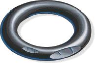
▪ Elastomeric O-ring secondary seal design parameters
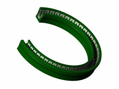
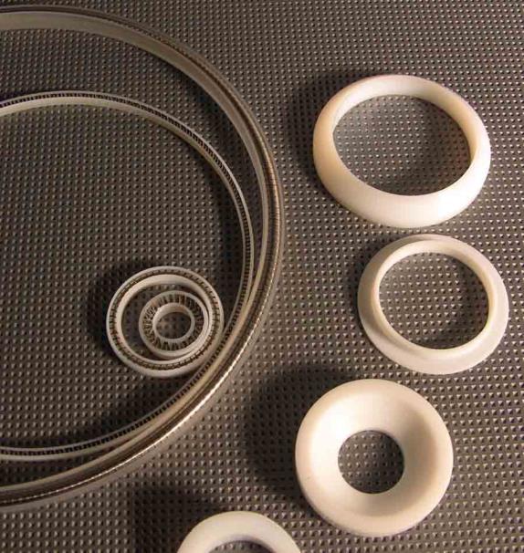
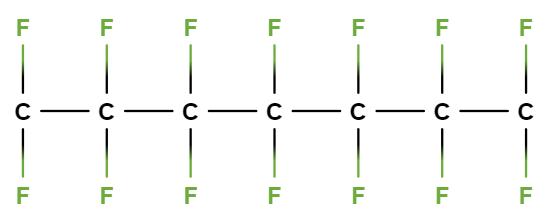
▪ Elastomeric/PTFE material and configuration options (including back-up rings)
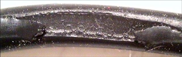
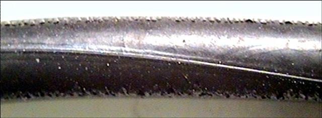
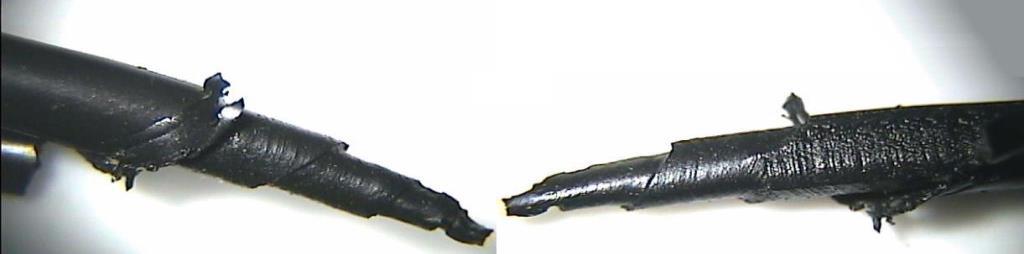
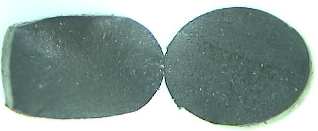
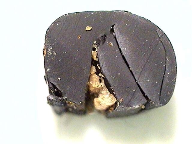
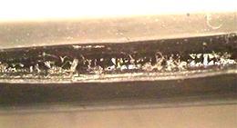
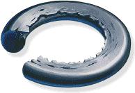
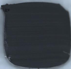
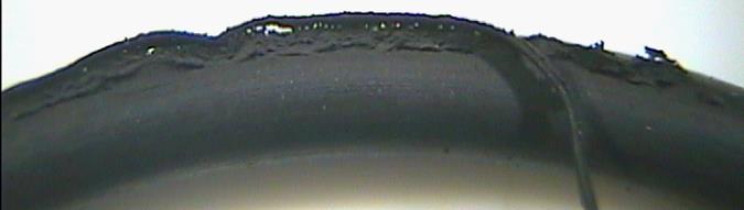
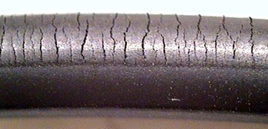
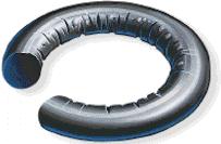
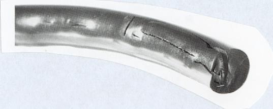
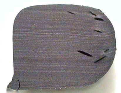
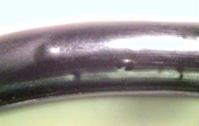
▪ Common secondary seal failure modes
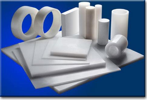
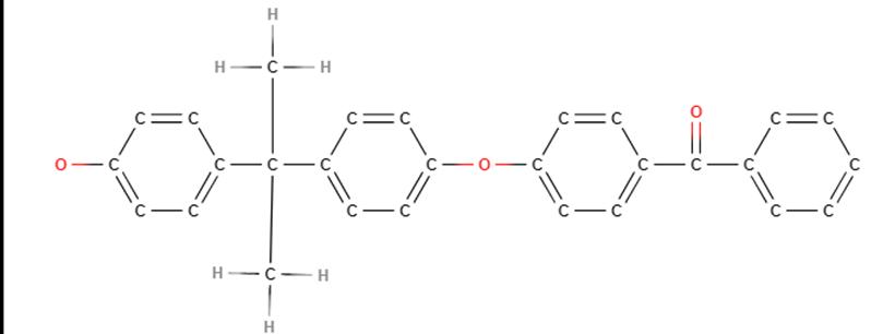
▪ Thermoplastic and other material options
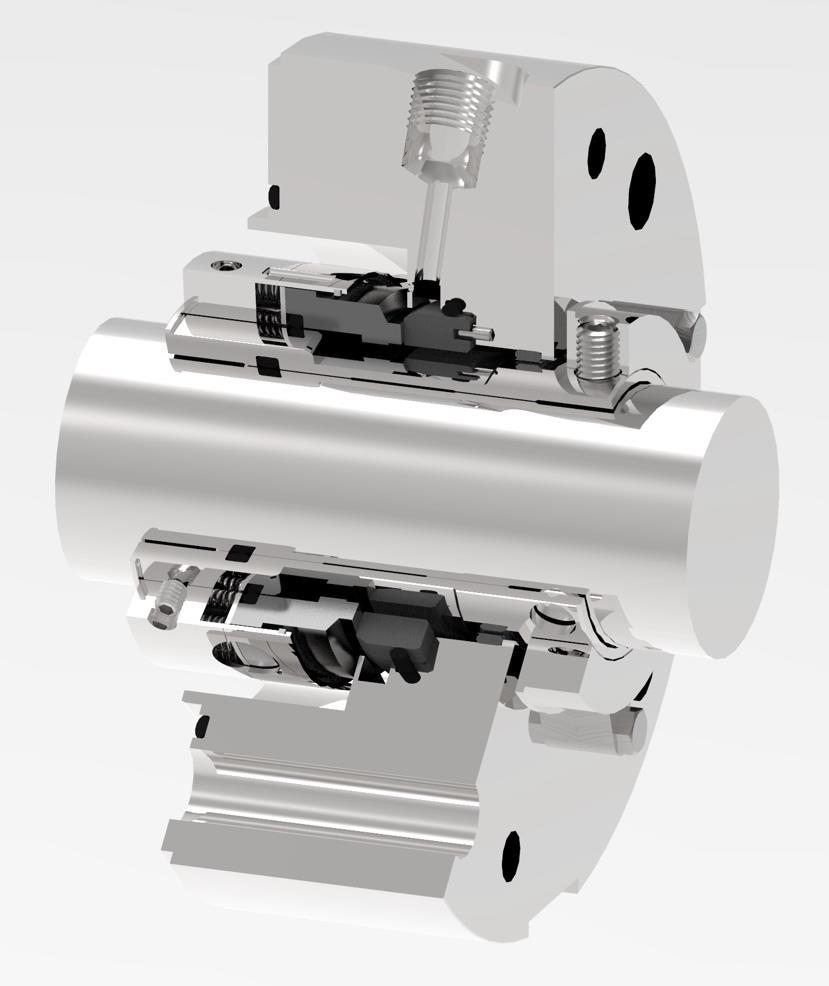
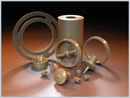
Mechanical Seal Basic Components
Rotating Assembly
Sleeve
Rotating Primary Ring
Stationary Mating Ring
Secondary Sealing Elements
Stationary Gland Plate
Locking Collar
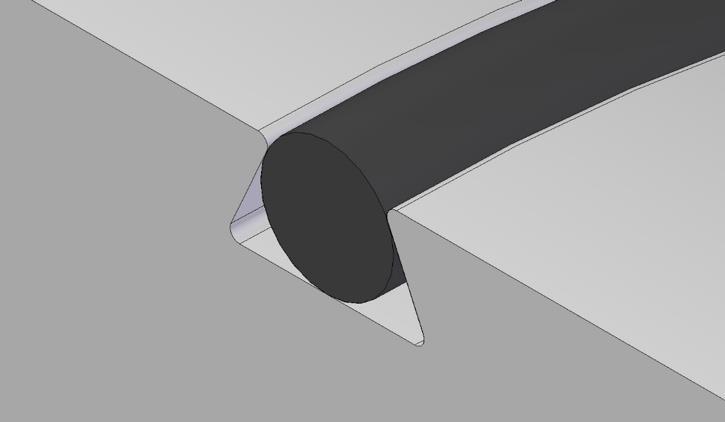
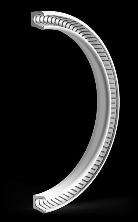
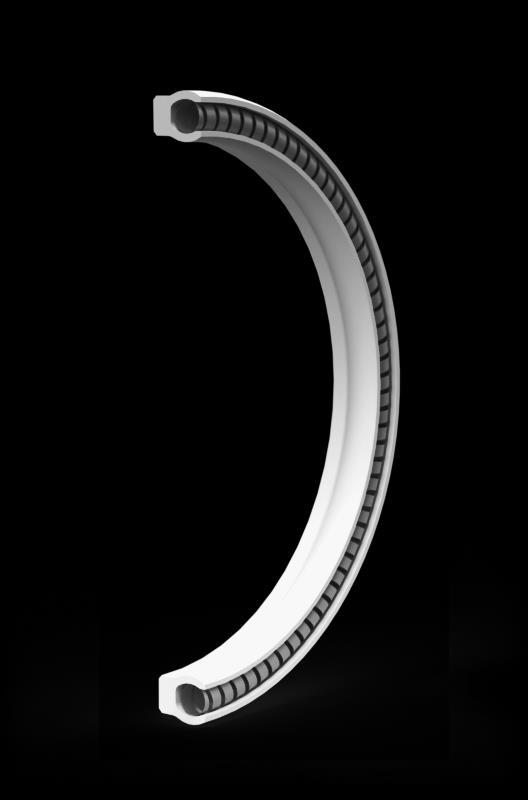
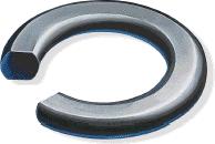
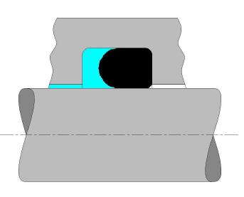
O-Ring in Groove
High Pressure Side Low Pressure Side
Groove OD
Groove ID
Groove Width
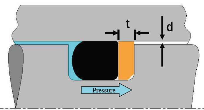
Extrusion Gap
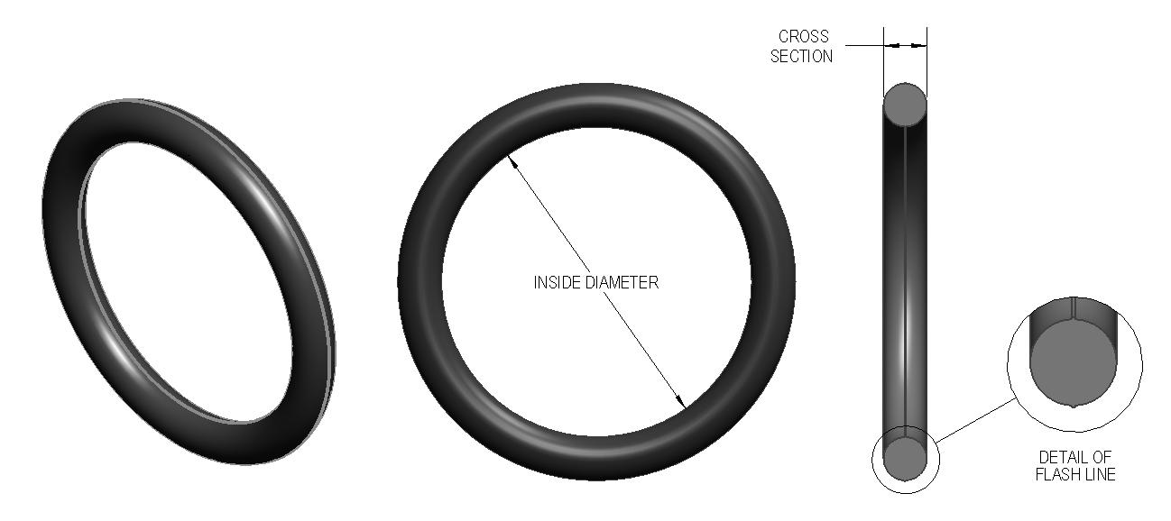
Elastomeric O-ring Design Parameters
Groove / O-ring Geometry
▪ Installed Stretch
▪ Installed Compression / Squeeze
▪ Cavity Fill
▪ Extrusion Gap
Physical Properties
▪ O-ring Hardness (Durometer)
▪ Coefficient of Thermal Expansion (CTE)
▪ Chemical Swell
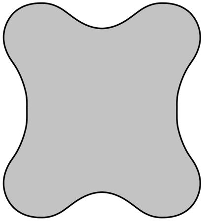
▪ Compression Set
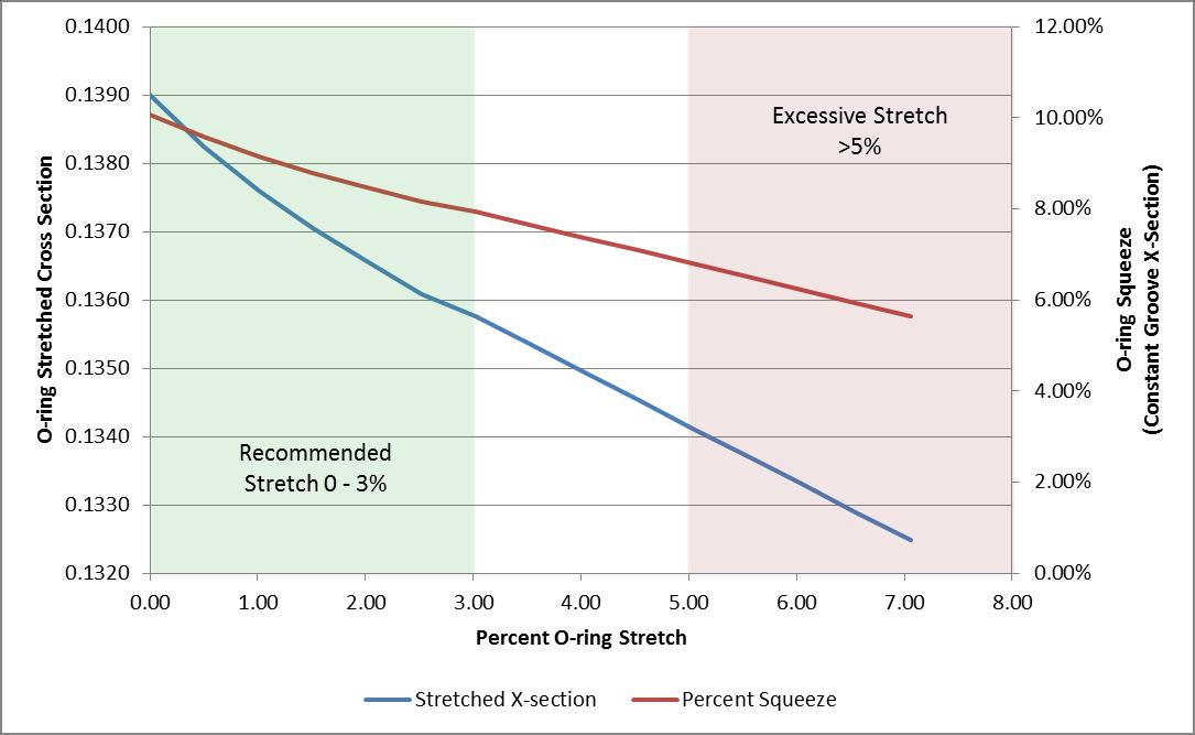
O-Ring Stretch
▪ Example case: AS-568 size 226 (2.000” Nominal ID O-ring)
▪ O-ring Cross section changes in non-linear relationship with stretch
▪ Excessive stretch may cause O-ring breakage or failure due to high internal stresses (Gow-Joule Effect)
Installed Compression / Squeeze
▪ Squeeze is required for the O-ring to effectively seal
▪ Pre-loads the O-ring against the sealing surfaces
▪ Typical squeeze:
▪ 10% – 15% for static O-rings
▪ 5% – 10% for dynamic O-rings
▪ Depends on O-ring cross section, use, tolerances of O-ring and Groove
▪ Specialty designs may deviate from these typical numbers
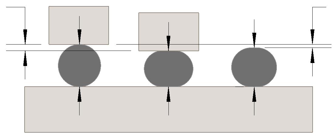
Cavity Fill
▪ The percentage of free volume or cavity fill of an Oring is affected by thermal growth and chemical swell in operation
▪ Normal fill range is highly design dependent
▪ High fill conditions can limit ability of O-ring to flex or move as required
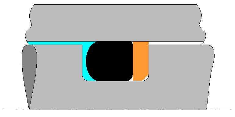
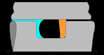
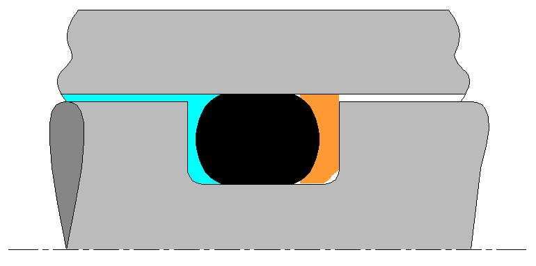
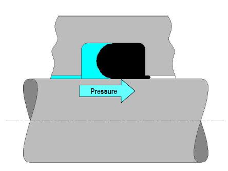
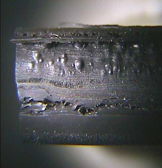
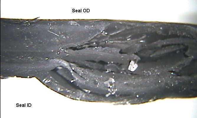
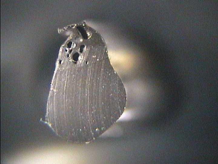
▪ Overfill can cause seal failure through:
▪ Extrusion of O-ring
▪ Component failure due to high stresses
Linear Coefficient of Thermal Expansion (CTE)
▪ Elastomers grow at a substantially higher rate than steels or ceramics, resulting in an effective increase in squeeze and a reduction in free volume
▪ Perfluoroelastomer (FFKM) ~ 170 x 10-6 in/in/°F (300 x 10-6 m/m/°C)
▪ Fluorocarbon (FKM) ~ 95 x 10-6 in/in/°F (170 x 10-6 m/m/°C)
▪ Ethylene Propylene (EPDM) ~ 89 x 10-6 in/in/°F (160 x 10-6 m/m/°C)
▪ Nitrile (NBR) ~ 62 x 10-6 in/in/°F (110 x 10-6 m/m/°C)
▪ Stainless Steel ~ 9 x 10⁻⁶ in/in/°F (16 x 10-6 m/m/°C)
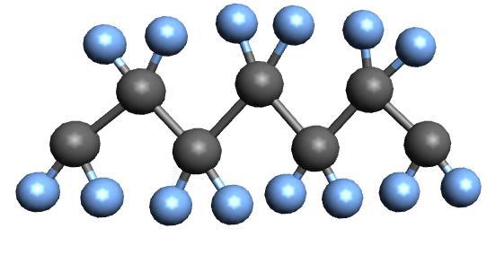
Excellent compression set and resistance, limited temperature range.
Use in Avoid in Water/steam, acetone, diluted acids and caustics, ketones
Mineral oil, solvents, aromatic HC
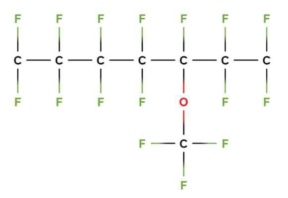
Elastomer Materials – FKM (Fluorocarbon)
Excellent high temperature resistance with good chemical resistance and compression set properties. Use in Avoid in Mineral oils, some acids and bases, HC, low concentration H2S
Amines, ketones, steam, and selected acids
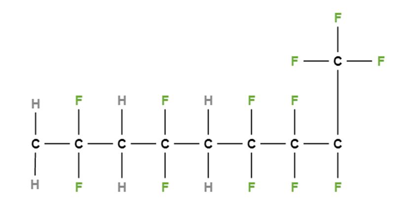
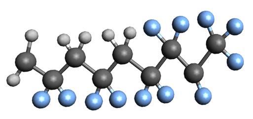
Hexafluoropropylene
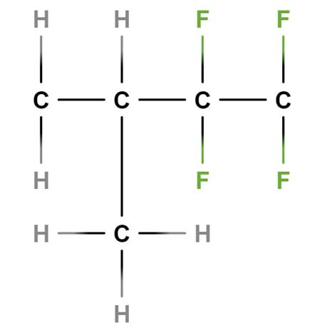
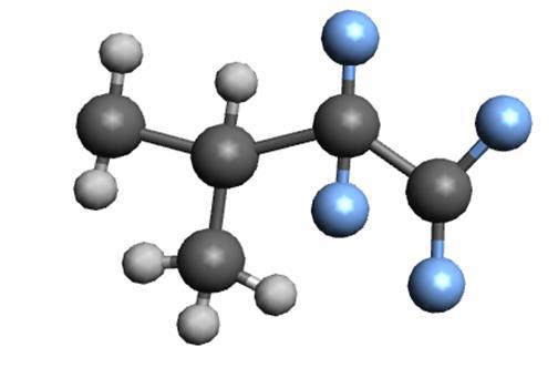
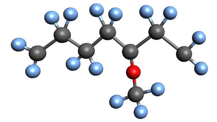
Elastomer Materials – FEPM
Excellent heat and chemical resistance.
Use in
Water/steam, mineral oils, thermal oils, hydraulic fluids, H2S up to 35%, amines, radiation