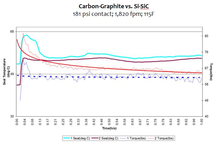
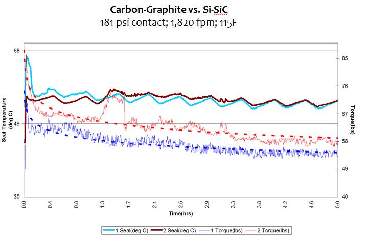
Mechanical Seal Face Materials DISCLAIMER While the FSA makes every reasonable attempt to ensure that the information contained in this document is accurate and current, the FSA, its officers, directors, volunteers, and authorized agents are not responsible for any errors or omissions contained therein nor are they responsible for any results obtained from the use of or reliance upon its content. All information is provided “AS IS,” with no guarantee of completeness, accuracy, timeliness or of the results obtained, and without warranty of any kind, express or implied. In no event shall FSA or its officers, directors, volunteers, or authorized agents be liable to you or anyone else for any decision made or action taken in reliance on the information con tained herein or for any for any consequential, indirect, special, or similar damages, even if advised of the possibility of such damages. The informa tion contained in this document is for informational purposes only and does not constitute professional advice. It also includes references to certa in standards that may change over time and should be interpreted only in light of particular circumstances. It is your sole responsibility to confi rm the current state of any referred to standards. FSA reserves the right to modify or update the document content and to modify this Disclaimer at any t ime, effective upon posting of an updated version of this Disclaimer.
© (April, 2023), Fluid Sealing Association. All Rights Reserved.
Abstract This Fluid Sealing Association Knowledge Series training presentation provides an overview of materials use for primary and mating rings in mechanical seals. This overview includes:
▪ Most common materials available
▪ Distinguishing characteristics and properties
▪ Application-specific considerations
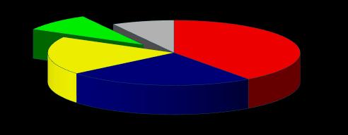
Causes of Mechanical Seal Failure ▪ Seal Face materials are estimated to contribute to less than 9% of all mechanical seal failures.
▪ A significant portion of those failures are associated with improper material selection for the application, not the materials themselves.
Based on “third party” published data.
Materials Overview Face Materials ▪ Mechanical Carbon
Alumina
Tungsten carbide
Silicon carbide
Other
Mechanical Carbon: Raw Materials Raw Materials Filler (20-80%) – Natural Graphite, Synthetic Graphite, Petroleum Coke, Lampblack
Binder (15-50%) – Synthetic Resins, Coal Tar Pitch, Petroleum Pitch, Metals, Carbohydrates
Additives (0-10%) – Film Formers, Abrasives, Antioxidants, Graphitizing Aids
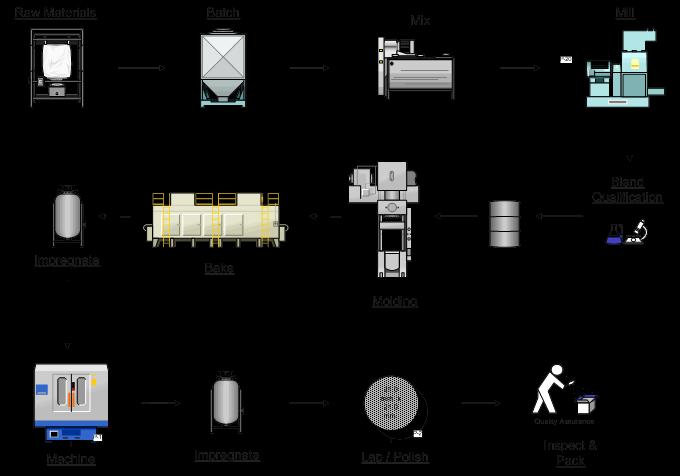
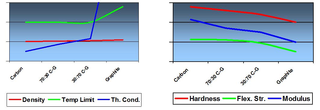
Mechanical Carbon: Process Overview Effects of Composition on Physical Characteristics Improved Chemical Resistance Carbon CarbonGraphite Graphite
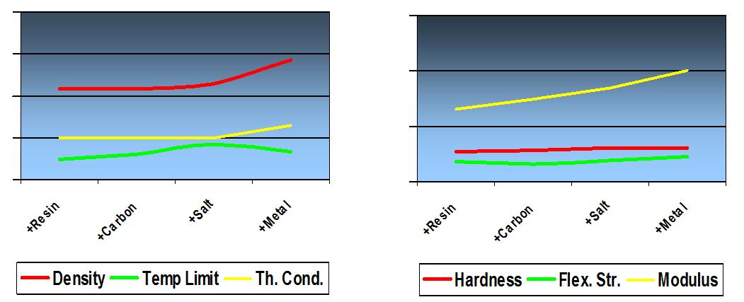
Effects of Impregnations on Physical Characteristics Mechanical Carbon: Effects of Impregnation on Tribology Carbon-Graphite (70:30)
375 psi contact, 75 fpm, Air Block on SAE 4620 Ring
Mechanical Carbon: Run-In effects ▪ Break-in period is associated with all contacting face seals after which a steady state condition can be expected.
▪ This break-in is affected by:
▪ Flatness of both faces
▪ Surface finish of both faces
▪ Contact Pressure
▪ Temperature
▪ Medium
▪ More graphitic materials will inherently transfer material to harder mating material.
▪ Lack of lubrication during break-in (i.e. dry run) will tend to exaggerate the severity of the break-in.
Mechanical Carbon: Materials Selection Impregnation Service Thermoset Resin
General duty to 260°C / 500°F in Water, Coolants, Fuels, Oils, Light Chemical solutions, Food and Drug
Carbon
Antimony
Film Formers (Fluorides etc.)
Highly corrosive environments
Oxidation Inhibitors (Phosphates etc.)
Steam, Light Hydro-carbons, Higher duty
Dry running, Cryogenics, Vacuum
Higher temperature and speed, Turbine engine applications to 245 m/s / 800 ft/sec. and 540°C / 1000°F
Mechanical Carbon: Materials Selection Fundamental Conditions for Satisfactory Carbon Operation
▪ Presence of Absorbable Gas
▪ Proper Carbon Material Selection
▪ Proper Running Surface Preparation
▪ Proper Mating Material Selection
Conditions When Carbon Materials Should Not Be Used
▪ Certain Oxidizing Chemicals
▪ Temperatures Higher than 650°C / 1200°F with Oxygen Present
▪ Abrasives in the interface
▪ Dry Running (No Absorbable Gas) in the Absence of Film Formers
Mechanical Carbon: Net Face Contact Pressure Limits Face Materials: Grade Application Grade Recommendation Information
▪ Application conditions
▪ Think “Mating Pairs”
▪ Consider materials presently used in application
▪ Do the present materials work?
▪ Issues with the present application?
▪ Economics of present materials
▪ Purchase quantities of present materials
▪ Evaluation requirements for new material
▪ Additional information on application
Face Materials: Typical Mating Pairs Light & Heavy Duty Hydro-Carbon Applications
▪ Antimony Impregnated Carbon vs. Reaction Bonded SiC
Highly Corrosive Applications
▪ Impregnated Graphite vs. Self Sintered SiC
Steam Application
▪ Impregnated Carbon vs. Reaction Bonded SiC
▪ Antimony Impregnated Carbon vs. Reaction Bonded SiC
Hot Water Applications
▪ Impregnated Carbon vs. Reaction Bonded SiC
Dry Gas Applications
▪ Antimony Impregnated Carbon vs. Reaction Bonded SiC
Face Materials: Application Carbon Graphite
Silicon Carbide
Tungsten Carbide
Alumina
Metal
Coatings
• Lubricity
• Corrosion Resistance
• Abrasion Resistance
• Stiffness
• Corrosion Resistance
• High Performance (P-V)
• Toughness
• Abrasion Resistance
• Stiffness
• Abrasion Resistance
• Stiffness
• Ease of Fabrication
• Applicable to Various Material
• Abrasion
• Brittleness
• Corrosion
• Thermal Shock
• Lower Performance
• Delamination
• Wear-through Not Self Lubricating
Alumina: Material Processing Raw Materials
Powder Preparation
Alumina, Ceramic oxides, binders
Wet Ball Mill, Spray Dry
Forming a Compact
Dry Pressing, Iso-pressing, Extrusion, CIM
Making it a Solid
High Fire Sinter, 1440 -1650°C
Diamond Grinding OD, bore, face grinding, lapping & polishing
View /Packing Inspection & Packing
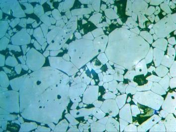
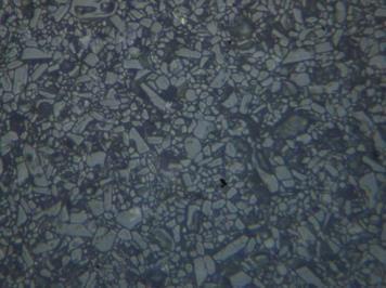
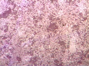
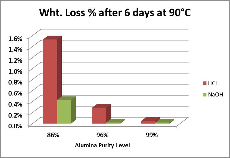
Alumina: Materials Options Enhanced chemical resistance General duty Pump shafts, bearings, and seal faces Medical Applications
Alumina: Characteristics Prime Features
▪ Exceptionally hard-wearing
▪ Excellent abrasion resistance
▪ High compressive and flexural strengths
▪ Dense, non-porous and vacuum tight
▪ Excellent dimensional stability across very wide temperature range
▪ Resists chemical attack at higher purity levels
Tungsten Carbide: Processing Raw Materials Tungsten Carbide, Metal binders
Forming a Compact Dry Pressing, Iso-pressing
Making it a Solid High Fire Sinter, >2,000°C
Diamond Grinding
OD, bore, face grinding, lapping & polishing
View /Packing Inspection & Packing
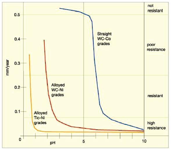
Tungsten Carbide: Material Types Considered a Cemented Carbide Binder determines corrosion resistance:
▪ Cobalt Bound – Least corrosion resistant
▪ Nickel Bound – Preferred for most sealing applications (~6% binder)
▪ TiC-Ni Bound – Highest corrosion resistance.
Tungsten Carbide: Characteristics Prime Features
▪ Tough (non-brittle)
▪ Exceptionally hard-wearing
▪ Excellent abrasion resistance
▪ High compressive and flexural strengths
▪ Dense, non-porous and vacuum tight
Silicon Carbide: Processing Raw Materials
Powder Preparation
Silicon Carbide, Carbon, binders
Spray Dry
Forming a Compact Dry Pressing, Iso-pressing
Making it a Solid
High Fire Sinter, >2,000°C
Diamond Grinding
OD, bore, face grinding, lapping & polishing
View /Packing Inspection & Packing
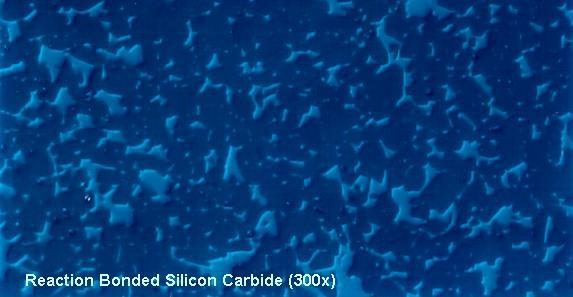
Silicon Carbide: Reaction Bonded Reaction Bonded SiC (SiSiC) • SiC + C + Si SiC + SiC
Silicon Carbide Silicon
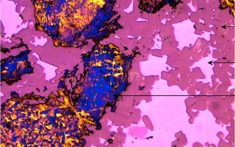
Silicon Carbide: Reaction Bonded + Graphite Reaction Bonded SiC with Graphite (SiSiC-G)
• SiC + C + Si SiC
Silicon Carbide
Silicon
Graphite
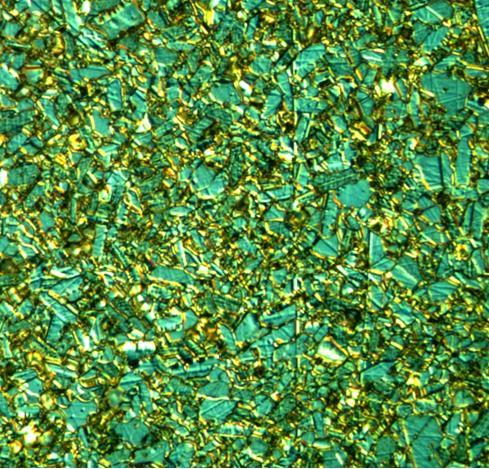
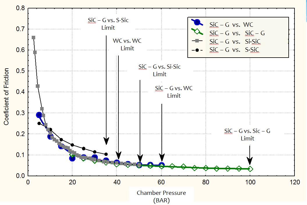
Silicon Carbide: Self Sintered Self Sintered SiC (SiC) Face Materials: Increasing capability ▪ Improved Performance in Marginally Lubricated Conditions
▪ Capability for Dry-Run Survivability
▪ Enhanced Pressure-Velocity (P·V) Capability in Hardface combinations
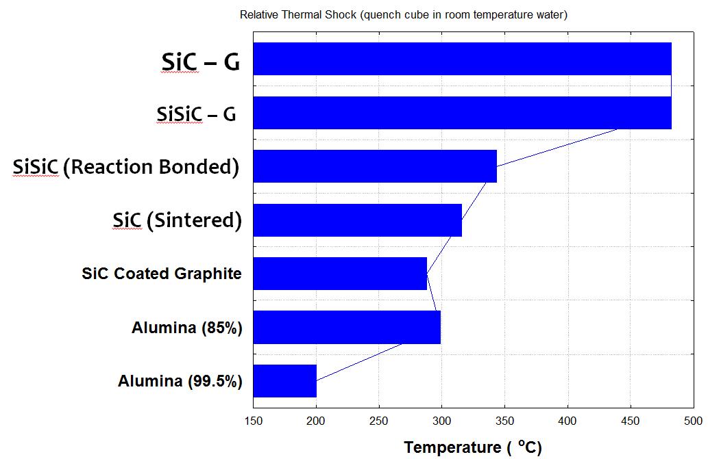
▪ Thermal Shock Resistance
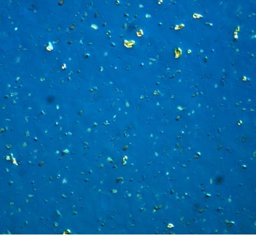
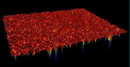
Face Materials: Superior Tribology ▪ Surface Roughness is required for contacting hardface materials.
▪ External Operation
▪ Matte Lapping (0.18-0.33 μm / 7 - 13 μin Ra) improves surface capabilities temporarily by ‘roughing up’ the surface
▪ Inherently rougher surface finish with a composite
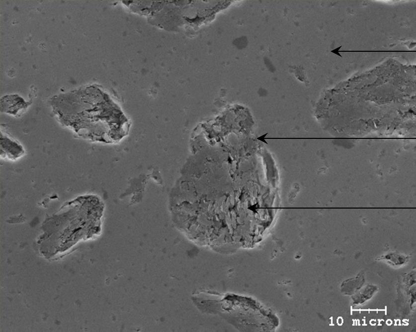
Silicon Carbide: Sintered SiC + Graphite Uniform Matrix
Well Bound Interface
Dense Graphite Agglomerate
Thermal Shock Resistance Enhanced Pressure-Velocity (P·V) Capability Controlled face topography, coupled with increased thermal conductivity, improve contacting hardface combinations’ capability


