FIN JOHNSON 20 22 Pr OF e SSION al P O rt FO l IOS el F S u S ta ININ g t O w N wOO dw O rk IN g Mater I al re S earc H ce N tre c era MI c S e x HI b I t ION de SI g N w atc HM aker S HQ
MOBILITY PAVILION
PROJECT OVERVIEW
Location: Dubai, UAE
Sector: Leisure
Work Stages: Technical Design
Area: 12,000 msq
Construction Cost: NA
Role: Architectural Assistant 2
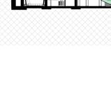
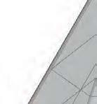
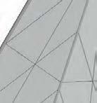
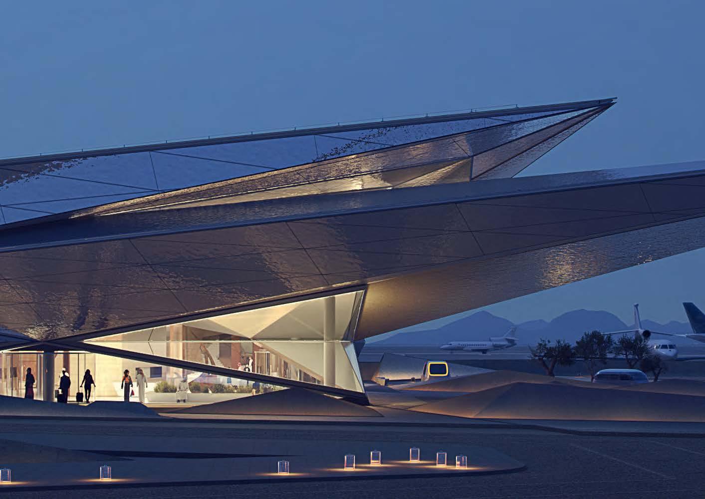
Welcoming visitors at one of the main entrances to Expo 2020 Dubai is Alif, a pavilion named after the first letter of the Arabic alphabet and dedicated to Mobility. From the outside, the building is curvaceous, but it hides a fantastical world: three giant figures of historical explorers, rendered in photo-realistic detail by our collaborating counterparts, the special effects team that worked on "The Lord of the Rings" films.
It's one of three thematic pavilions at the event, along with Opportunity and Sustainability. Together, they function as visual landmarks for the latest edition of the World Expo, an international exhibition that also hosts individual pavilions from 192 countries and will run for six months until the end of March 2022.
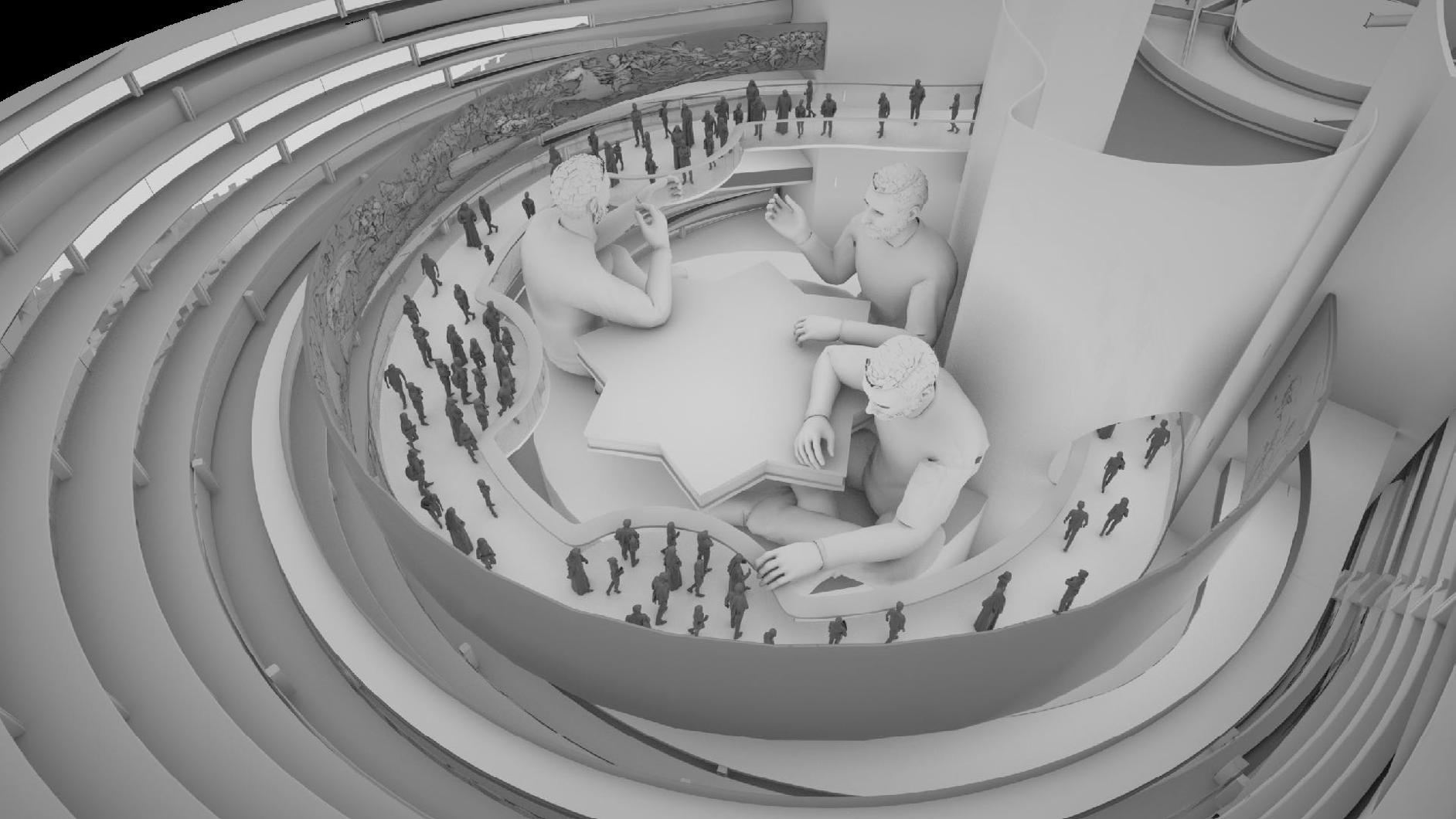
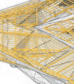
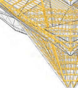
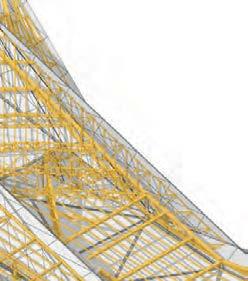
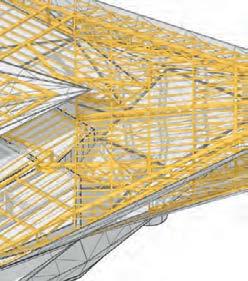
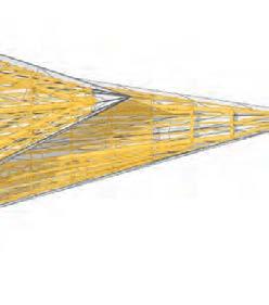
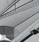
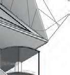
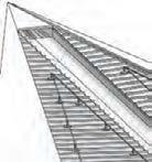
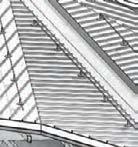
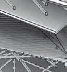
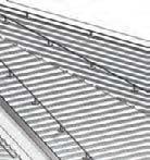
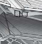
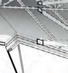
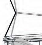
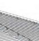
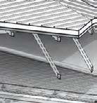
I was part of the design team at Foster+Partners, tasked with coordinating the exhibition space and designing the building to host the exhibition. A ribbed and curved shape to th building is meant to evoke movement. Inside, three main galleries are connected by a central core that hosts the world's largest passenger elevator, with a capacity of 160 people.
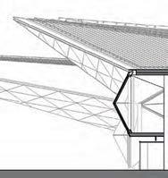
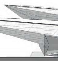
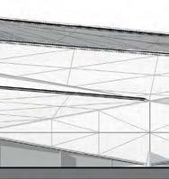
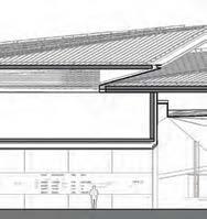
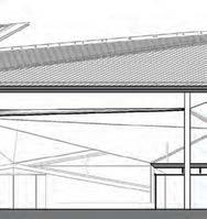
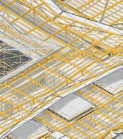
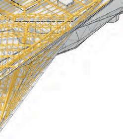
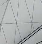
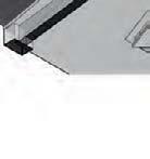
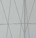
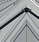
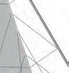
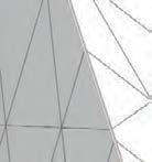
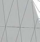
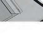
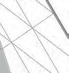
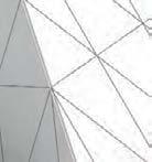
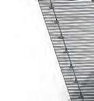
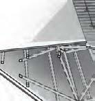
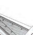
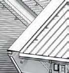
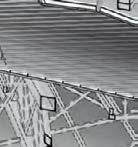
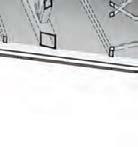
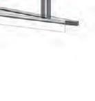
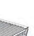
tH e curved r I b S OF t H e bu I ld IN g SHO wca S e t H e I dea OF MO b I l I ty a N d MO ve M e N t. tH e r I b S are F u N ct ION al al SO a N d H el P t O regulate S u N l I g H t w I t HIN t H e bu I ld IN g. THE PAVILION


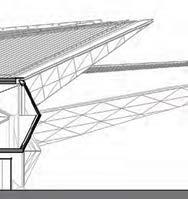
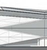
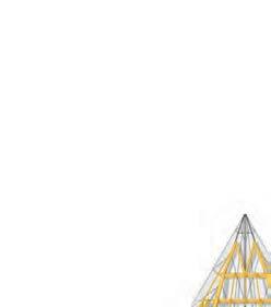
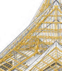
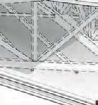
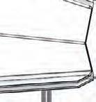
THE BUILDING PETALS


ake u ected by a ce t H bu I ld IN g by c O llab O rat IN g w I t H weta w O rk SHOP
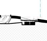
Site Boundary 3.00m setback demarcation HST Site Secondary LV Landlord switchroom Waste Recepient Room MEP central Room Secondary LV Landlord switchroom Petal A MEP Zone Combined Mechanical Plantroom Security Office Public Toilet Lobby Moving Platform Lift pit Cafe Area Serving Point Amphitheatre Cafe Area Cafe Area Central Lobby Entrance Vestibule External Queuing Area IDF Room Exhibition Corridor 3 RFS-405 Petal C Exhibition Space Terrace RFS-401 RFS-402 EWS-101 RFS-408 BOH Exhibition BOH Store Exhibition Corridor 1 Exhibition Corridor 1 MEP Pump room MEP Electrical room Petal C Attic Petal C skylight HST Fire Pump Room Fire Water Tank Central MEP Petal B MEP MTR Service Corridor Retail Kitchen Exhibition Area Corridor 3 3.0m setback demarcation RFS-405 RFS-401 RFS-402 EWS-101 RFS-408 Petal B Exhibition Space Act 3 BOH Store Exhibition Area Exit Main Central Lobby Central moving platform lift shaft moving platform lift pit BOH Store Exhibition Corridor 1 MEP room Public Toiltes Entrance vestibule Exhibition Corridor 2 Electrical room MEP Plants Petal B Attic IDF Room Landlord LV switchroom RMU Room Petal B Terrace External queuing area Petal B Skylight high-level RAHUs E E E E E E E E E AM-202 AM-405 AM-201
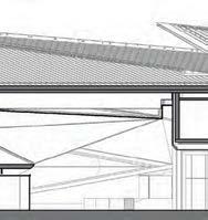
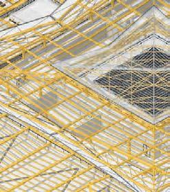
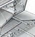
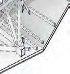
tH e g I a N t S table F u N ct IONS a S a SP ace w H ere t H e P ubl I c ca N ex P er I e N ce t H e SP ectacle OF t H e g I a N t S tH e P ub I c P a SS al ON g a ra MP w H ere t H ey ca N IN teract a N d lear N ab O ut t H e HIS t O ry OF MO b I l I ty.
9 Document Title Chapter Opener Headline THE PHYSICAL WORLD ACT I EXPO 2020 DUBAI | MOBILITY PAVILION 37
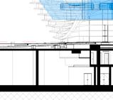
INSIDE THE ATRIUM


THE PHYSICAL WORLD ACT I
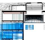
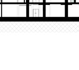
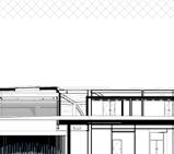
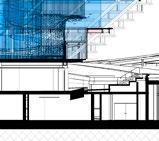
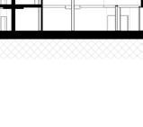
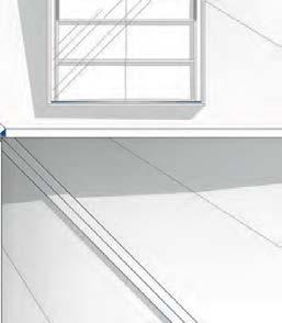
LOREM IPSUM DOLOR SI t a ME t, U t SUMO U t RO q UE EUM , an EOS S a LE I gn O ta g R a E c I , c I v I b US DELE ct US I n DUO . Ha S at S t E t an IM a L , U t H a S v E n I a M HOMERO RE c US ab O , n O MODO n O n UMES HIS PAGE TITLE Level Lower Ground-FFL -4.200 Level Ground Floor-FFL 0.000 200840 360 3000 450 FFL -4.200 FFL +0.000 FFL -2.850 2910 1040
LOREM IPSUM DOLOR SI t a ME t, U t SUMO U t RO q UE EUM , an EOS S a LE I gn O ta g R a E c I , c I v I b US DELE ct US I n DUO . Ha S at S t E t an IM a L , U t H a S v E n I a M HOMERO RE c US ab O , n O MODO n O n UMES HIS PAGE TITLE 204620 Varies 1600 1530 50 1550 900 100 1050 5 204620 STR-102 30 1000 240 R50 R 50 R50 Glass Ballustrade Steel Fixing Steel Structure Concealed Light Fitting Corian or similar Cladding Concealed Light Fitting 10mm Shadow Gap 20 10 R25 STR-102 20 15 58010140 120150 270 2725 Varies 6 6 R5 Adhesive Plywood Steel Plate Precast Concrete Thread 80 80 Stainless steel non slip strips R23 R25 110 50 Glass Ballustrade Stainless Steel Ballustrade Stainless Steel Ballustrade Fixing to Glass 2060 1 10 1 Feature Stair_Landing Section 5 2 Feature Stairs_Fascia Detail 3 Feature Stairs_Fascia 3D 5 4 Thread Detail 5 5 Ballustrade Fixing
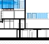
LOREM IPSUM DOLOR SI t a ME t, U t SUMO U t RO q UE EUM , an EOS S a LE I gn O ta g R a E c I , c I v I b US DELE ct US I n DUO . Ha S at S t E t an IM a L , U t H a S v E n I a M HOMERO RE c US ab O , n O MODO n O n UMES HIS PAGE TITLE Level 01-FFL 4.200 Level 01-SSL 4.050 Level 01-FCL 3.000 204621 320 830 50 1100 840 240 Low iron shatter proof curved glass Stainless steel, bespoke profile extrusion ballustrade Bespoke high-gloss white GRP Panels Concealed LED strip lighting Concealed LED strip lighting Bespoke high-gloss white GRP Fascia BAL-101R Lin-918 15070100 R50 R 240 240 R200 Concealed glass ballustrade fixing Concealed LED strip lighting Level 01-FFL 4.200 Level 01-SSL 4.050 Level 01-FCL 3.000 880320 BAL-101R LIN-918 LIN-918 BAL-101R 10 1 Atrium Fascia Section 5 2 Atrium Fascia Detail 20 3 Atrium Fascia elevation 4 Atrium_Fascia 3D
LOREM IPSUM DOLOR SI t a ME t, U t SUMO U t RO q UE EUM , an EOS S a LE I gn O ta g R a E c I , c I v I b US DELE ct US I n DUO . Ha S at S t E t an IM a L , U t H a S v E n I a M HOMERO RE c US ab O , n O MODO n O n UMES HIS PAGE TITLE
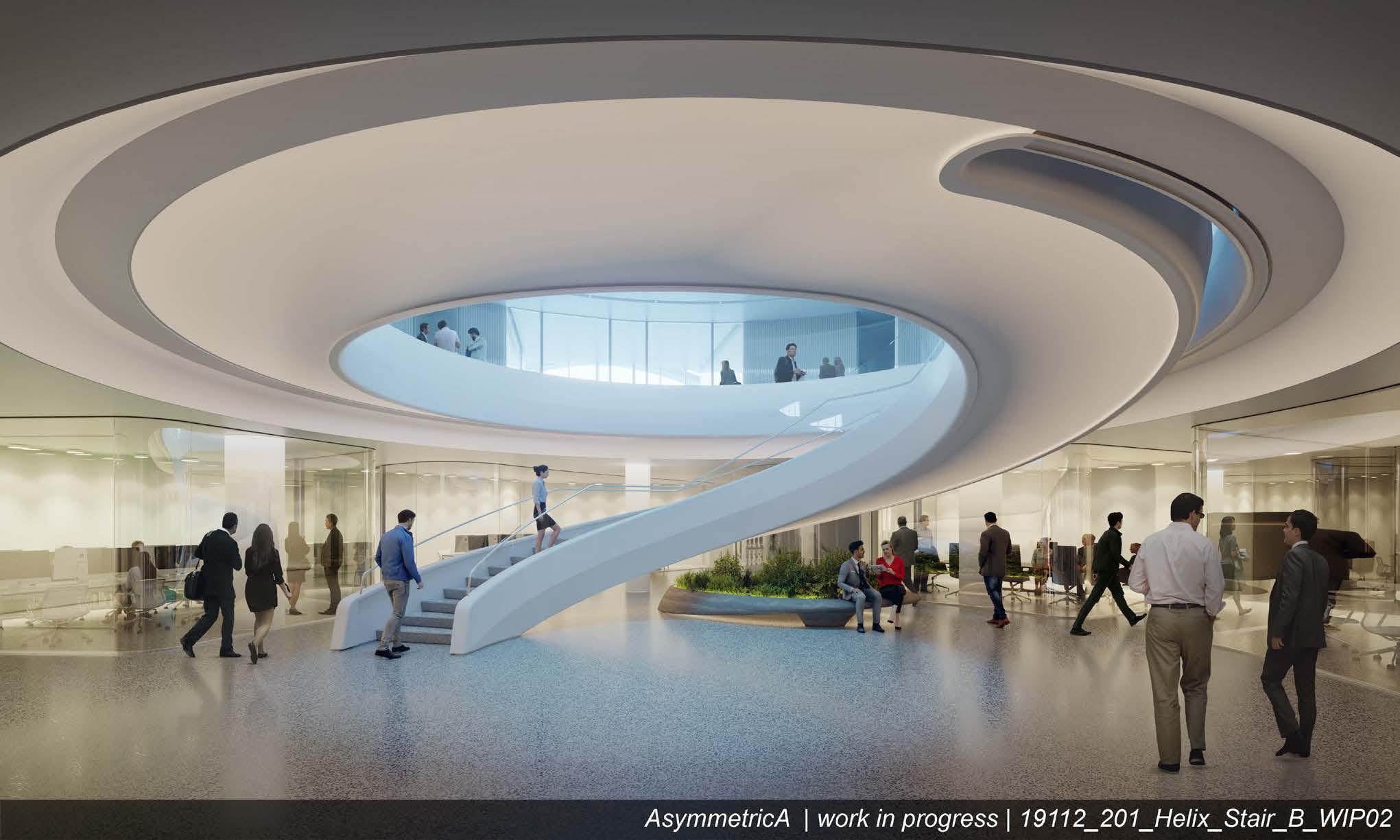
AMAALA
PROJECT OVERVIEW
Location: Saudi Arabia
Sector: Aviation
Work Stages: Technical Design
Area: 16,000 msq
Construction Cost: NA
Role: Architectural Assistant 2
Write something
, c , RE c US ab O , n O MODO n O n UMES HIS 1 Schematic Design 1500101-FOP-3671911125-33211100-000001 Revision C02 12th August 2020


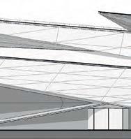
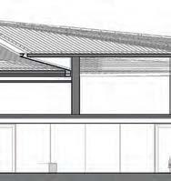
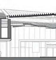
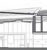

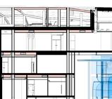
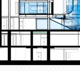
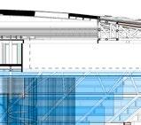
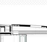
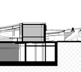
LOREM IPSUM DOLOR SI t a ME t, U t SUMO U t RO q UE EUM , an EOS S a LE I gn O ta g R a E c I , c I v I b US DELE ct US I n DUO . Ha S at S t E t an IM a L , U t H a S v E n I a M HOMERO RE c US ab O , n O MODO n O n UMES HIS PAGE TITLE 60 Illustrative East-West Transversal Section AT-Level 00 79.800 85.200 AT-Lower Ground Level 74.300 4675 FFL +79.800 FFL +74.300 FFL +79.800 FFL +79.800 FFL +83.700 FFL +79.800 FFL +79.800 FFL +74.200 4580 4400 VIP Drop off Pick up Staff Service Access Arts Lounge F&B Central Courtyard Oasis Wellness Lounge F&B Access Control Wellness AT-Level 01 85.200 E C B A AT-Roof Level 88.800 +79.800 FFL +85.200 +79.800 Airfield Apron CIP Drop off Pick up MEP Central Courtyard Offices 2699 3023 16800 16800 FCL +11.518 FCL +14.494 FCL +14.372 FCL FCL +12.353 FCL +13.476 FCL +14.494 Top of Roof Level 94.300 1 200 1 Passenger Terminal Building, Section 01 Passenger Terminal Building, Section 02 AT-Level 00 79.800 AT-Level 01 85.200 D E F G C B A AT-Lower Ground Level 74.300 AT-Roof Level 88.800 Airfield Apron CIP Drop off / Pick up CIP Arrivals Gate CIP Concourse Emergency Exit CIP Concourse Emergency Exit AT-Level 00 79.800 AT-Level 01 85.200 AT-Lower Ground Level 74.300 AT-Roof Level 88.800 Top of Roof Level 94.300 16800 16800 16800 16800 16800 16800 AT-Level 00 79.800 AT-Level 01 85.200 E C B A AT-Lower Ground Level 74.300 AT-Roof Level 88.800 AIRSIDE LANDSIDE Airfield Apron CIP Drop off Pick up VIP Arrivals Gate VIP Drop off / Pick up CIP Concourse Emergency Exit Top of Roof Level 94.300 16800 16800 1 200 1 Passenger Terminal Building, East Elevation 1 200 2 Passenger Terminal Building, West Elevation 61 AT-Level 79.800 Drop Access Control AT-Level 00 79.800 01 D F G AT-Lower Ground Level 74.300 FFL +85.200 FFL +79.800 FFL 4600 AIRSIDE LANDSIDE Departure Security Control VHNWI/HNWI Departure Concourse (Airside) 3278 16800 16800 16800 16800 16800 +13.476 FCL +14.372 FCL +11.518 1 200 2 79.800 85.200 G C AT-Lower Ground Level 74.300 88.800 AIRSIDE LANDSIDE FFL +79.800 AT-Lower Ground Level 88.800 94.300 16800 00 79.800 01 D F G AT-Lower Ground Level AIRSIDE VIP 16800 16800 16800 16800 16800


LOREM IPSUM DOLOR SUMO EOS DELE at S MODO PAGE TITLE 208


LOREM IPSUM DOLOR SI t a ME t, U t SUMO U t RO q UE EUM , an EOS S a LE I gn O ta g R a E c I , c I v I b US DELE ct US I n DUO . Ha S at S t E t an IM a L , U t H a S v E n I a M HOMERO RE c US ab O , n O MODO n O n UMES HIS
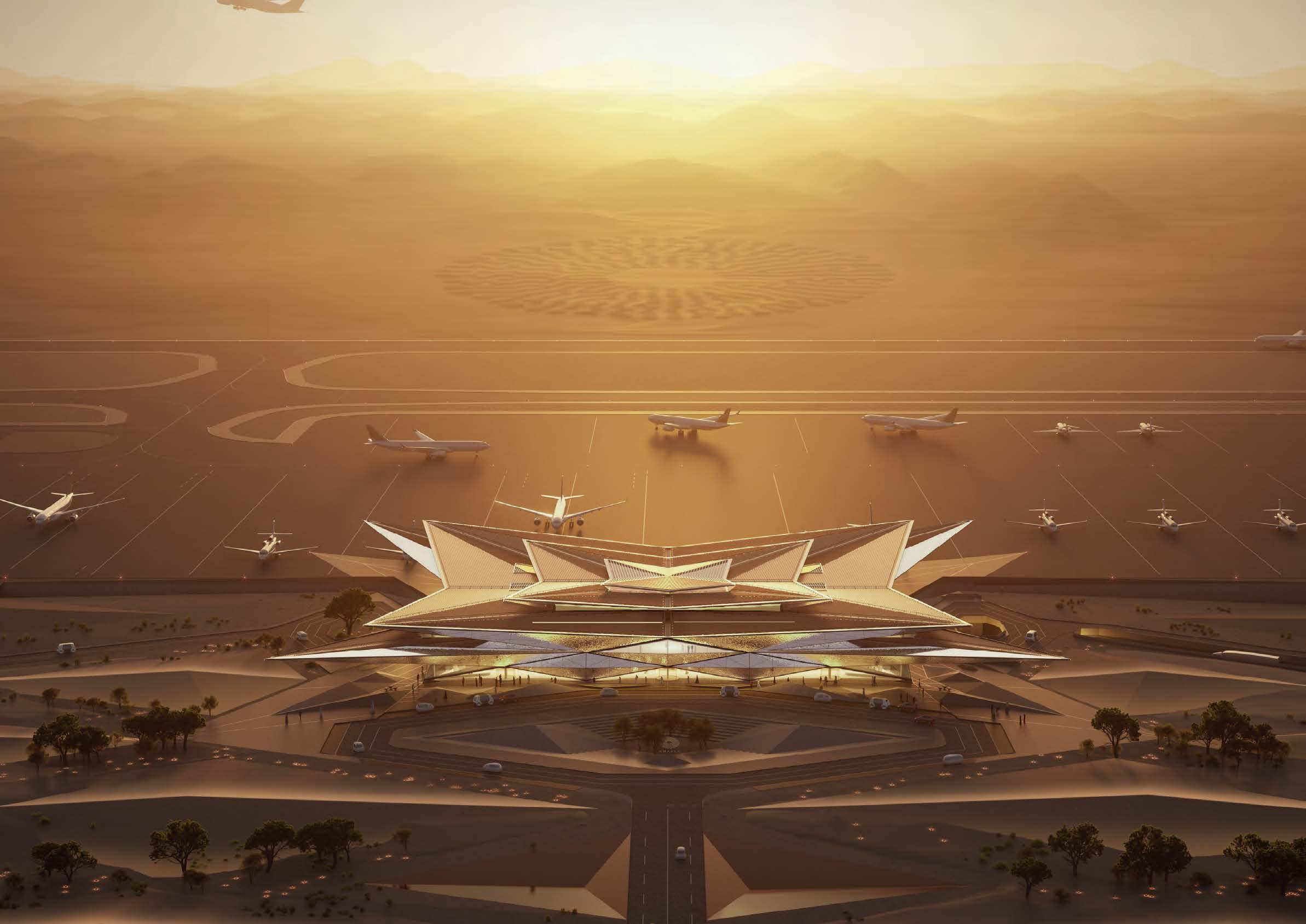
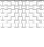
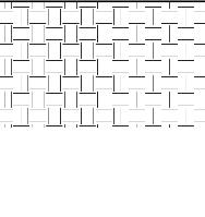
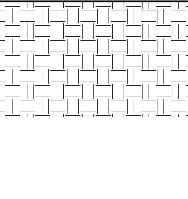
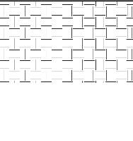
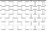
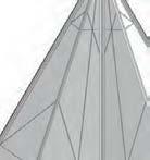
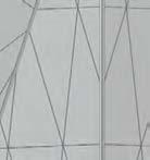
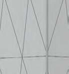
Surface 02 Pattern Mirrored from SRF 01 Surface 01 Pattern
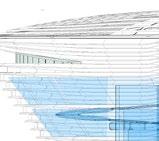
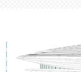
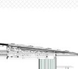
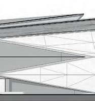
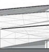
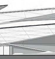
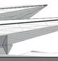
FACADE PANELISATION


EWS-103 EWS-103 DRS-701 EWS-402 EWS-101 EWS-104 RFS-203 EWS-104 EWS-101 CAN-101 RFS-202 RFS-203 N Client Project Title Project No Sheet First Issue Date Scale at ISO A0 Sheet Number Revision Key Plan. Do not scaledrawings. Dimensions govern. All dimensions are in millimetresunlessnoted otherwise. Alllevels are in metres unless noted otherwise. Alldimensionsshall be verified on site beforeproceeding with the work. Foster+ Partners shall be notified in writing of anydiscrepancies. Any areas indicated on thissheet are approximate and indicative only. Riverside, 22 Hester Road London SW11 4AN www.fosterandpartners.com T+44(0)20 7738 0455 F+44(0)20 7738 1107 Rev. Date Reason For Issue Chk Foster+Partners 2019 Project address 1500101-FOP-36-71911219Foster + PartnersArchitecturaldrawingsand models are coordinated with the followingEngineering models: Studio Structural RevitModel 1500101-SIE-367911217-ZZ-23-33213114-000001.rvt dated 30th July 2020 1500101-SIE-367911217-Z1-36-33213114-000001.rvt dated 30th July2020 Studio Electrical RevitModel 1500101-SIE-367911217-ZZ-23-33213121-000001.rvt dated 21st July 2020 1500101-SIE-367911217-Z1-36-33213121-000001.rvt dated 16th July2020 Studio Mechanical Revit Model 1500101-SIE-367911217-ZZ-23-33213117-000001.rvt dated 21st July 2020 1500101-SIE-367911217-ZZ-36-33213117-000001.rvt dated 09th July 2020 C01 Amaala Company Amaala Terminal Building and Control Tower 06/16/20 ZZ-ZZ-33211100-010540 2954 Passenger Terminal Building Details Typical Systems Visual / Diagram -EWS 104 Shard Soffit Tier 1 Kingdom Center, 58th Floor Riyadh -Kingdom of Saudi Arabia 1 Visual Diagram -EWS 104 Shard Soffit Tier 1 2 Visual / Diagram -EWS 104 Shard Soffit Tier 1 Copy 1 C0112/08/2020100%SD Submission JB/ ISW EWS-104 EWS-104 DRS-701 DRS-701 EWS-103 EWS-101EWS-402 EWS-104 CAN-101 RFS-203 RFS-202RFS-203 EWS-104 Axonometric RFS-201 FACADE DEVELOPMENT tH e g I a N t S table F u N ct IONS a S a SP ace w H ere t H e P ubl I c ca N ex P er I e N ce t H e SP ectacle OF t H e g I a N t S tH e P ub I c P a SS al ON g a ra MP w H ere t H ey ca N IN teract a N d lear N ab O ut t H e HIS t O ry OF MO b I l I ty.
LOREM IPSUM DOLOR SI t a ME t, U t SUMO U t RO q UE EUM , an EOS S a LE I gn O ta g R a E c I , c I v I b US DELE ct US I n DUO . Ha S at S t E t an IM a L , U t H a S v E n I a M HOMERO RE c US ab O , n O MODO n O n UMES HIS PAGE TITLE Facade Panelization Selected Option - Zoom in Detail Visual of Mirage Panel Expresssion at Night
SHEEPHOUSE
PROJECT OVERVIEW
Location: Oxfordshire, UK
Sector: Commercial
Work Stages: Technical Design
Area: 4,000 msq
Construction Cost: NA
Role: Architectural Assistant 1
Sheephouse will become the headquarters of a luxury English watch making firm. They intend to use the building as their head office as well as the factory which they are set to produce all components of the watch in.
My involvement in this project was alongside a larger team of around 8, including architects and engineers. I was able to work on this project for a lot of the Tender phase and have thus been able to understand managing clients, tenants and landlords as well.
The level of detail provided by those working on the project encouraged the client to see our work in a wider context. Whilst the client is interested in this building in particular they also have multiple shops around the world from which they sell their products. Therefore, much of the interest in this project came from the bespoke furnishing we designed as they intend to replicate these throughout stores worldwide. This was never an initial brief but was created through attention to detail.
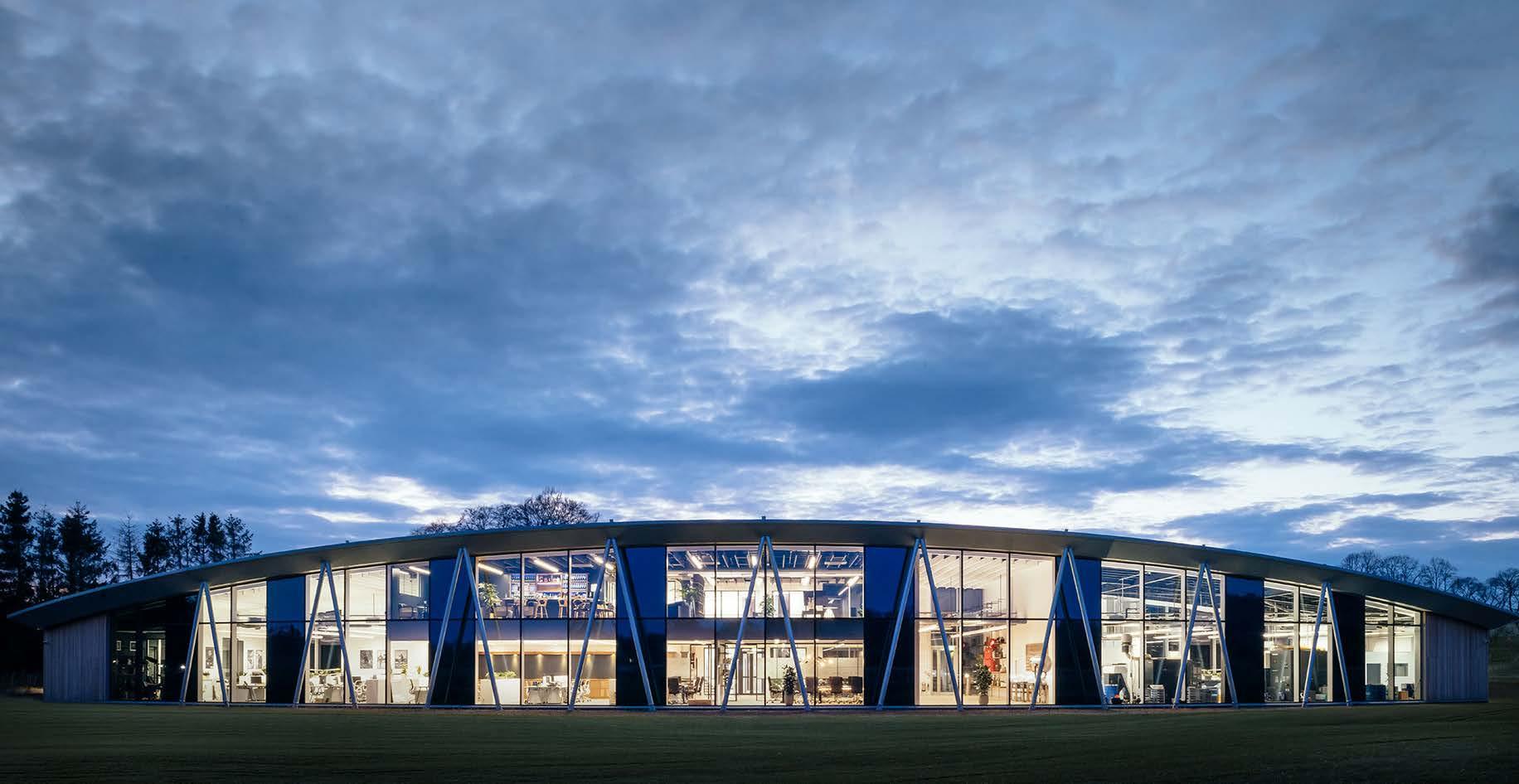
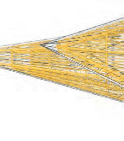
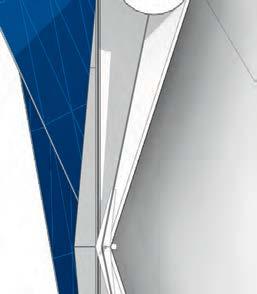
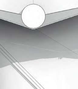
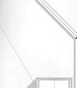
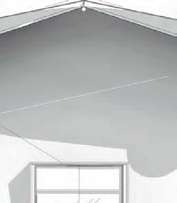
l uxury watc HM aker S HQ d e SI g N ed t O re P re S e N t t H e w IN g OF a P la N e a S t H e FI r M al SO H a S av I at ION a FFI l I at IONS
SHEEPHOUSE
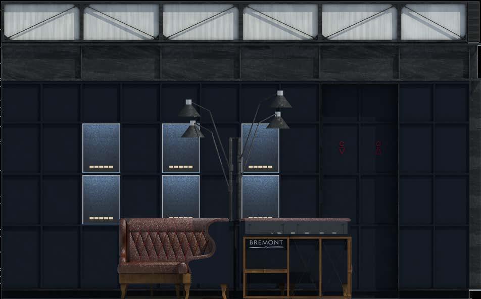
INTERIOR FINISHES STUDY
ARTICULATING THE LOBBY
I N O rder t O real IS e HO w t H e rece P t ION w O uld
c OM e t O get H er M y S el F a N d a Part 2 arc HI tect created a S er I e S OF F ur NISHIN g S tud I e S w HI c H ex P l O red t H e d IFF ere N t M ater I al S , a S well a S ty P e S OF F ur NI ture t H ey w O uld u S e IN t H e I r M a IN l O bby.
dISP lay u NI t S w H ere a large re Q u I re M e N t but wa N ted t O re M a IN S ubtle. aS t H e bra N d IS luxury
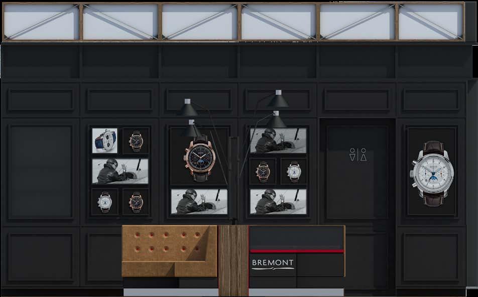
t H ey wa N ted F ew u NI t S but wa N ted t H e M t O tell t H e S t O ry OF t H e bra N d. tH e FI r S t S et OF F ur NI ture S tud I e S ex P l O red HO w t O d ISP lay t H e ev O lut ION OF t H e c OMP a N y a S a v IS ual ex P er I e N ce.
It w O uld S erve a S a N INFO r M at I ve, v IS ual l I brary
FO r IN ve S t O r S , a N d cl I e N t S t O ex P l O re w HI l S t at t H e H ead Q uarter S .
Muc H OF t H e dec ISIONS M ade regard IN g FINISH e S were d ON e u SIN g t HIS P r O ce SS OF de SI g N It wa S
e SS e N t I al FO r u S t O c ONSI der ge OM etry a N d all O wed
M e t O c ONSI der HO w a bu I ld IN g OF S uc H S cale
c O uld be F ea SI ble br O ke N d O w N IN t O M a N ageable
de SI g N ele M e N t S
1. 3. 2. 4.
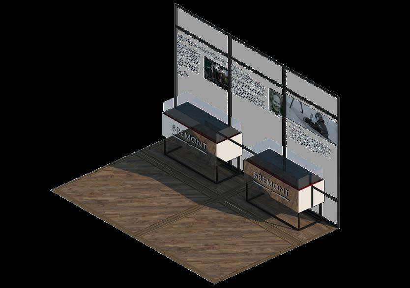
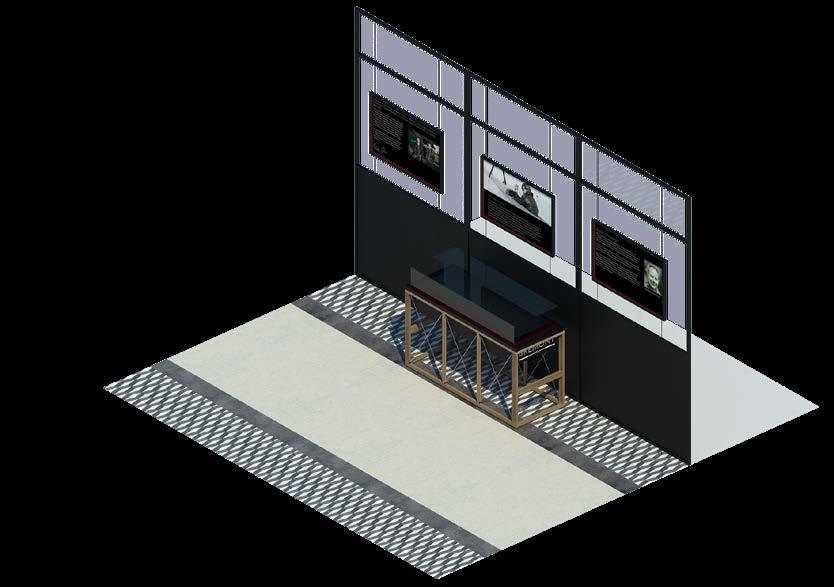
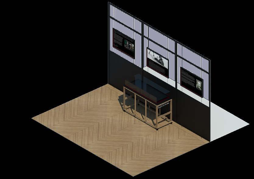
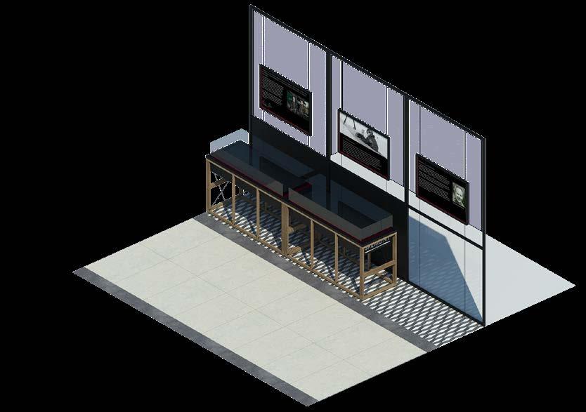
e ac H OP t ION SHO w S HO w t H e S t O ry OF b re MON t a S a bra N d c O uld be v IS ually c ON veyed t H r O ug H a c O rr I d O r SP ace.
FURNITURE STUDY
High level powder coated dark blue light box fixed to ceiling with
stainless steel Bremont
to front
See drawing PSS02838 for more details. Design to be signed off by Bremont and Spratley & Partners before construction.
White painted plasterboard wall within landlords design control zone (DCZ).
Hanging displays to contractors proposals within DCZ. See drawing 17.708.B.AS.2802 for details. Design to be signed off by Bremont and Spratley & Partners before construction.
Open beige leather lined display cubby with 3000k LED lighting. See drawing 17.708A.AS.2803 for more details.
Beige leather lined display spaces with 3000k LED lighting fixed shelves and lockable glass front. Satin stainless steel reveal. See drawing 17.708A.AS.2803 for more details.
Eq Eq Eq Eq TV
White painted cornice C872
Open dark blue painted oak veneer faced MDF storage cubbies.
Bremont clock. Satin stainless steel bezel and glass face mounted to openable panelling with 43" TV behind. See drawing PSS02842 for more details.
Full height dark blue painted oak veneer faced MDF panelling with Bremont clock. Colour and finish tbc.
Free standing service counter.
Relocate break
Lockable push release storage cupboards with adjustable shelving. Dark blue matt painted oak veneer faced MDF.
Storage cupboards with adjustable shelving and push realise concealed hinged doors with magnetic catches. Dark blue matt painted oak veneer faced MDF doors.
JOINERY DETAILS
blue
oak
DCZ. Low level prop
with satin
propeller. See
Design to be signed off by Bremont and Spratley & Partners before construction.
Line of shop frontage. Line of existing column behind panelling. Full height dark
painted
veneer MDF panelling within
display
stainless steel
drawing PSS02841 for more details.
satin
logo
face.
glass point and landlords alarm panel to behind service counter. 694 694 600 694 694 694 694 694 694 7400 600 600 2540 2420 Structural Slab 463 Shelf to be removed. Cubbie to provide sufficient space for till system. Screen 2 55" dimmable TV mounted within recess. Dimmable halo illuminated 1.5mm laser cut brushed stainless steel Bremont logo. See drawing PSS02839 for more details. Design to be signed off by Bremont and Spratley & Partners before construction. White painted cornice - C872 Dark blue painted oak veneer faced MDF to back of display space and reveals. Open beige leather lined display cubby with LED lighting. Full height dark blue matt painted oak veneer faced MDF panelling. Screen 1 - Outline of 43" dimmable TV behind panelling, Bremont clock. Satin stainless steel bezel and glass face mounted to openable panelling to contractors proposals. See drawing PSS02842 for more detail. Design to be signed off by Bremont and Spratley & Partners before construction. Stainless steel picture lights. Structural Slab New plasterboard suspended ceiling with openings for lighting and smoke extract to contractors proposals. See 17.708A.AS.2500 for more details. 708 Internal Elevation 1:50 A
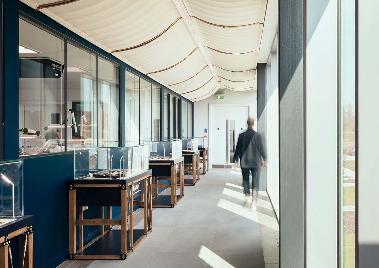
tH e FI r S t S et OF F ur NI ture S tud I e S ex P l O red HO w t O d ISP lay t H e ev O lut ION OF t H e c OMP a N y a S a v IS ual ex P er I e N ce. It w O uld S erve a S a N INFO r M at I ve, v IS ual l I brary FO r IN ve S t O r S , a N d cl I e N t S t O ex P l O re w HI l S t at t H e H ead Q uarter S
DISPLAY CABINETS
HIGH LEAS
PROJECT OVERVIEW
Location: Oxfordshire
Sector: Residential Work Stages: Developed Design
Area: 800 msq
Construction Cost: NA
Role: Architectural Assistant 1
High Leas is a residential project situated in Henley-on-Thames. The project brief was to put forward construction of a new dwelling on an existing tennis court, part of one owners plot of land. The new dwelling would occupy 1 acre in total and wanted to be ‘an eclectic use of sympathetic materials to give it a modern but unimposing look’.
Myself and 1 other architect worked together to realise the planning document. was given a series of hand sketches from which I then drew up the dwelling to take forward to planning.
Immediately this project through up the problem of producing a separate dwelling which would not impose on the local area, nor the existing land owners house. The street does not boast any new builds and thus creating a modern house would be an initial challenge.
Working on High Leas gave me real insight into putting together a full planning document. Producing the drawings to a standard which the client was happy with whilst also creating a design and access statement which would allow the council to give permission for the building to go ahead introduced me to the client/council balance in architecture.
The design and access statement challenged me to understand why particular materials and aesthetics might be required in particular locations. Moreover, under the constraints of client requirements I was able to cautiously indulge in spacial planning with the prospect of it actually being occupied. The project received planning permission however has not yet progressed to tender.
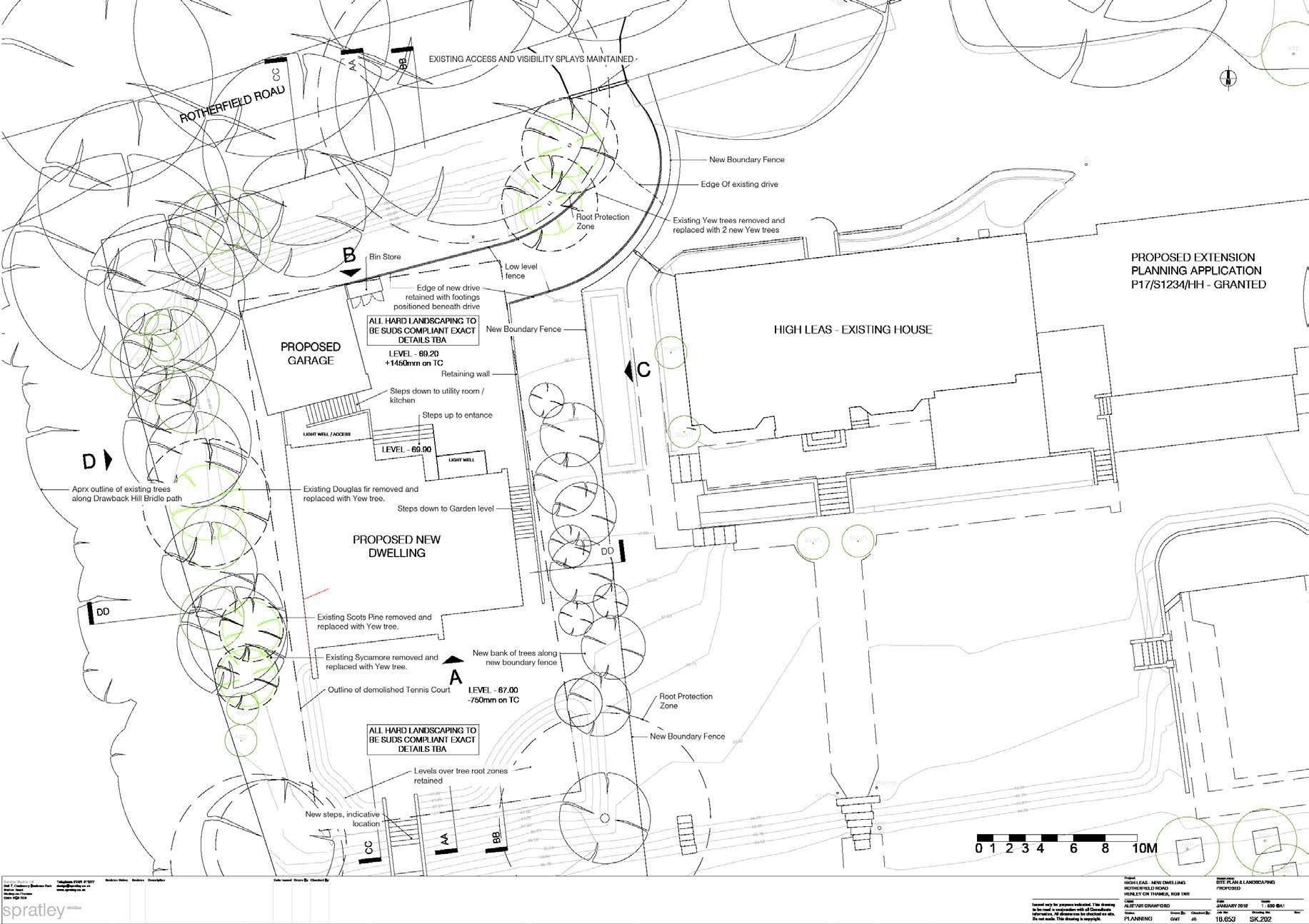
SITE PLAN
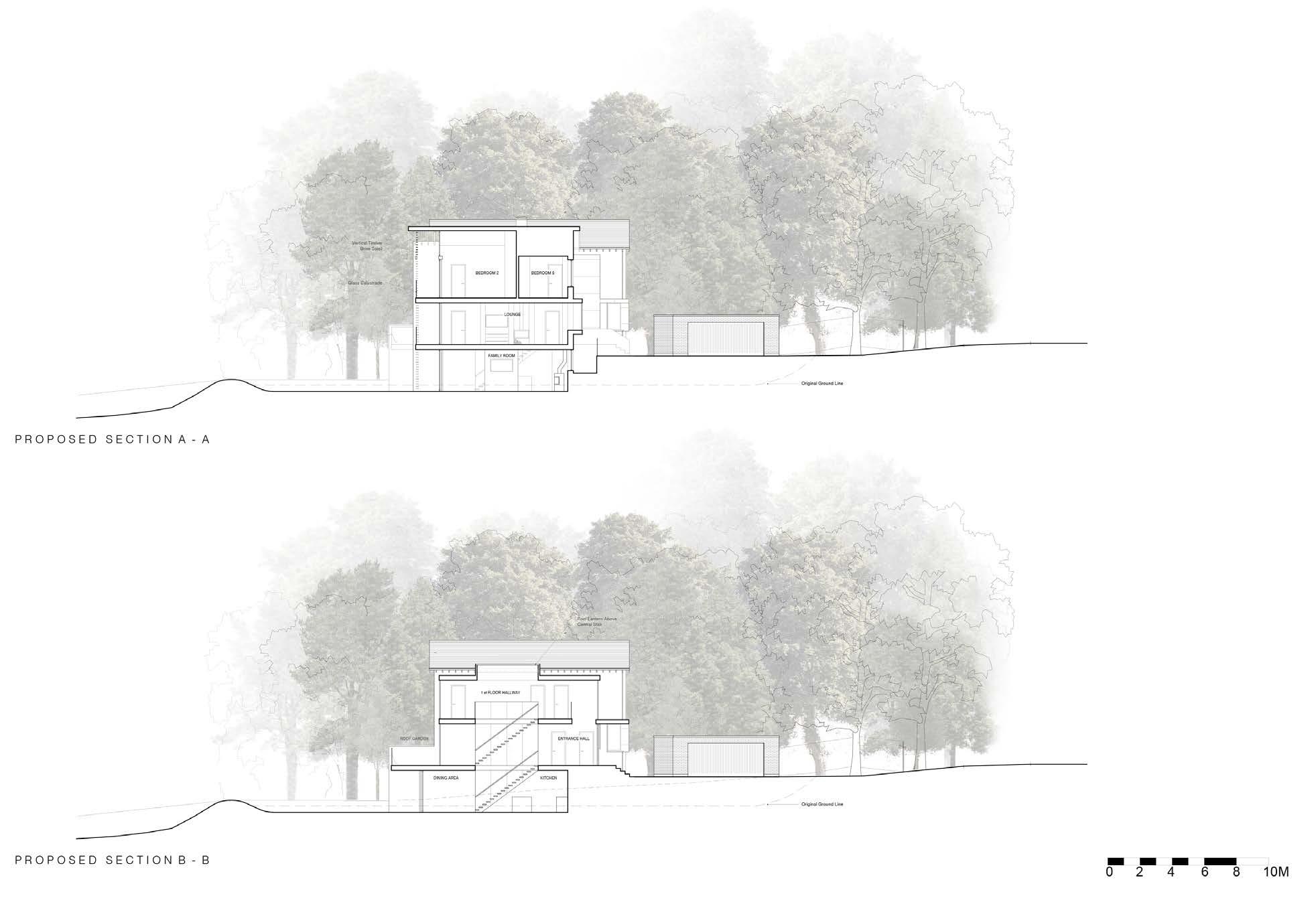
c e N tral c I rculat ION all O w S l I g H t t O P e N etrate IN t O t H e dwell IN g. tH e ba N k OF t H e HI ll all O w S t H e dwell IN g t O be t H er M ally regulated t H r O ug H N atural c ON d I t IONS
SECTIONS
ELEVATIONS
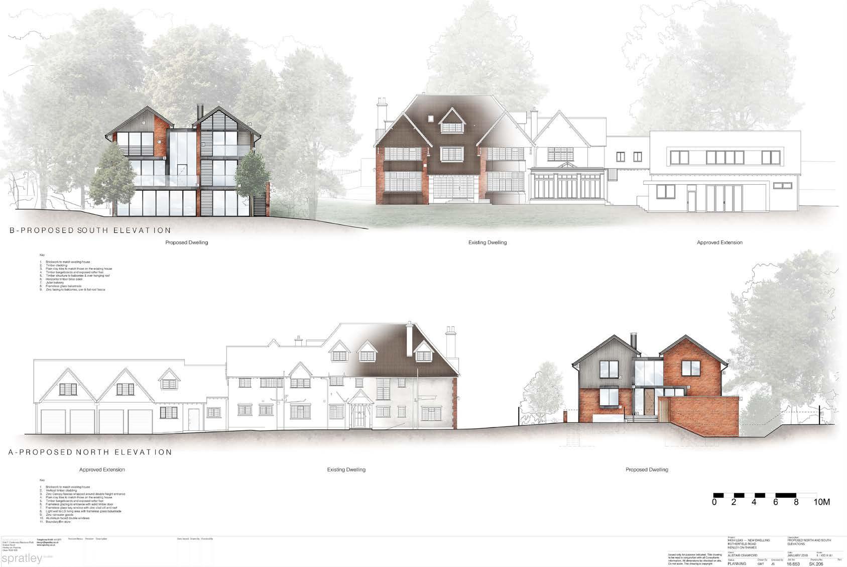
tH ree IN ter S ect IN g v O lu M e S P r O v I de OPPO rtu NI ty t O IN tr O duce vary IN g M ater I al S w HI c H all O w t H e bu I ld IN g t O ble N d S ucc IN ctly w I t H t H e IMM ed I ate e N v I r ONM e N t.