 S.S.T
S.S.T
T.O.C
BOOKLET
SITE ANALYSIS
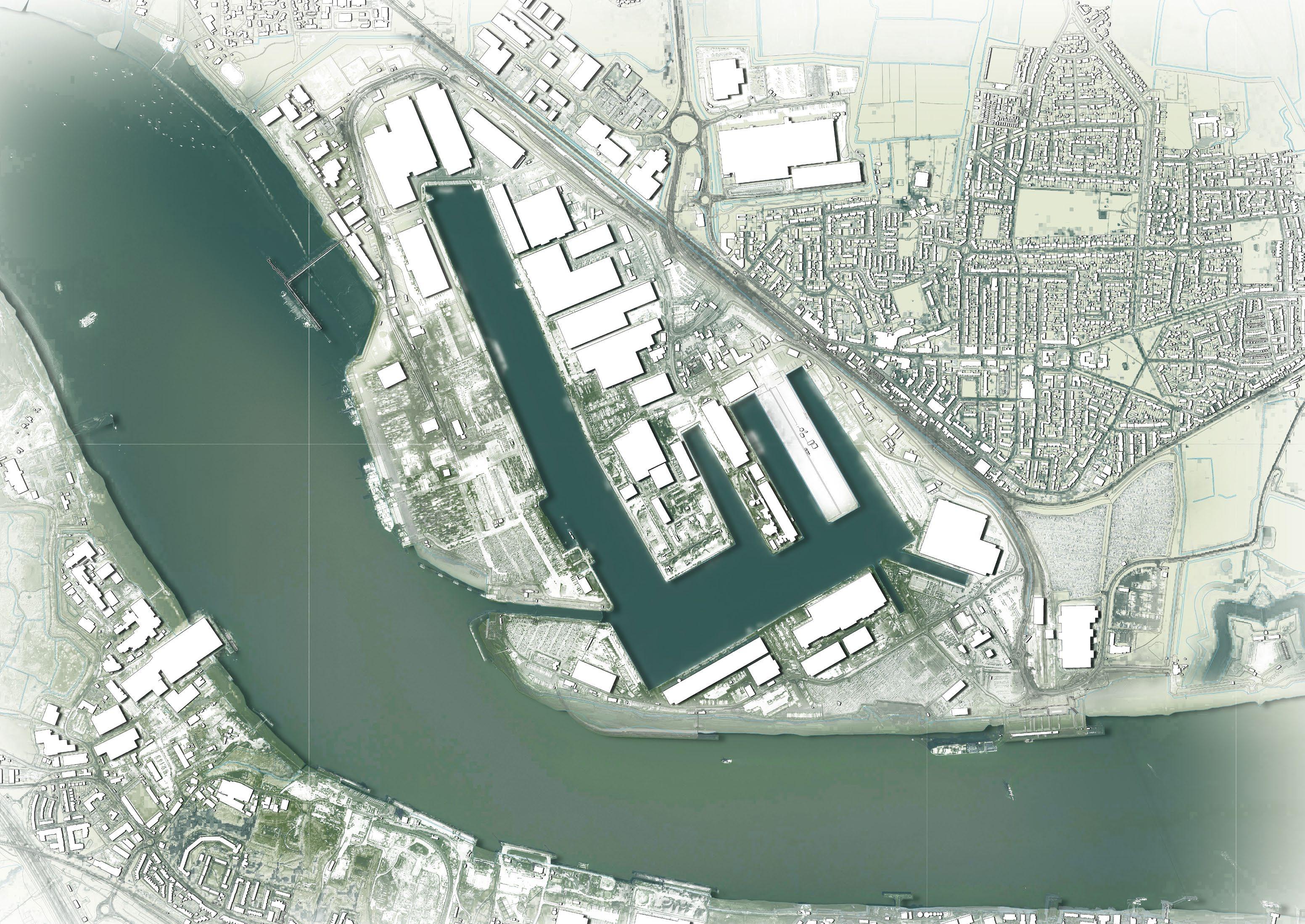
LOCATING TILBURY
Tilbury in a snapshot
SHIPPING
Tilbury & Global Trade
FLOODING
Flood risk analysis
INFRASTRUCTURE
On-site components
STRATEGY
100 PERSON Requirements
40,000 PERSON Requirements a a L.B.C
Living Building Challenge
DESIGN DEVELOPMENT
Iterative Progression
PROPOSAL
MASTERPLAN
Site Logistics
TILBURY TOWN
Connecting New & Old a a
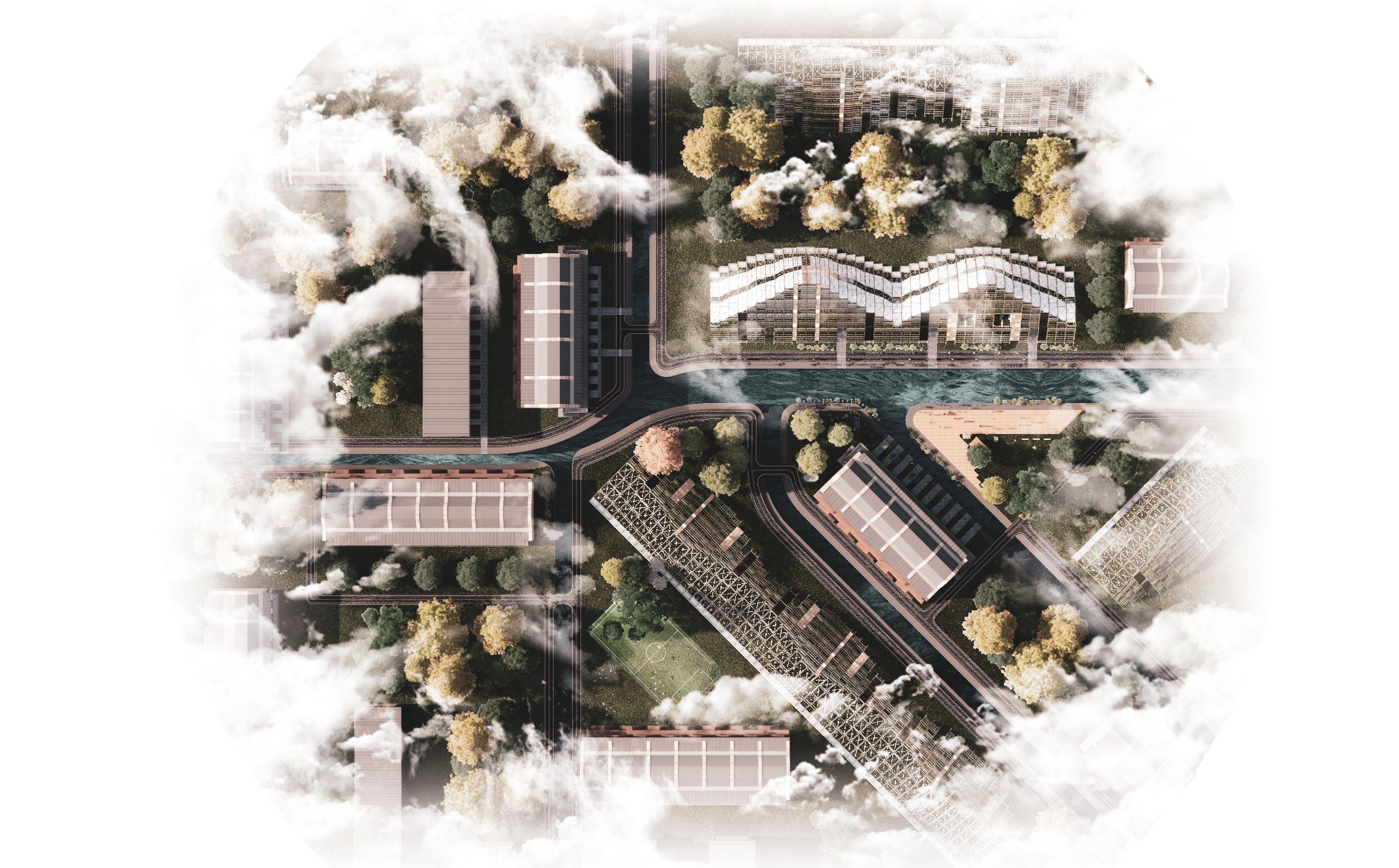
SITE PLAN
A Moment in Tilbury
AQUAPONICS
Food Growth
DWELLINGS
Cultural Transformation
T.O.C.
Table of con T en T s
T.O.C
BOOKLET
SITE ANALYSIS
LOCATING TILBURY
Pages 4 - 7
SHIPPING
Pages 8 - 10
FLOODING
Pages 11 - 15
INFRASTRUCTURE
Pages 16 - 21


STRATEGY
100 PERSON
Pages 23 - 25
40,000 PERSON
Pages 26 - 28 a a
L.B.C
Pages 29 - 31
DESIGN DEVELOPMENT
Pages 32 - 33


PROPOSAL
MASTERPLAN
Pages 35 - 39
TILBURY TOWN
Pages 40 - 41 a
Pages
AQUAPONICS
Pages
DWELLINGS
Pages 57 - 78


TILBURY PORT & FORT
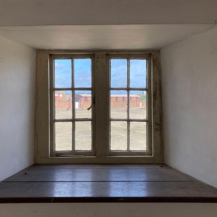
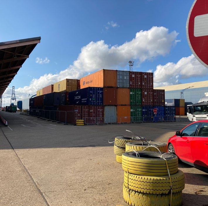


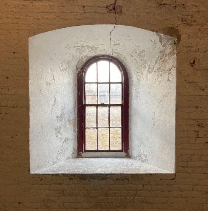


t ilbury p ort dra S tically juxtapo S e S the hi S torical fort which are S ituated 2km apart. t he port S va S t expan S e and building S engulf individual S and i S characteri S ed by the impermanence of it S S tock.


TILBURY GRAIN TERMINAL

SELF SUFFICIENCY


a family of four will require a total of 639m S q to be S elf S ufficient according to a S tudy carried out in denmark. t he average uk hou S e currently S it S on a plot of 90 S qm.
CLOSED LOOP PROGRAM


c ombining production with habitation allow S a community to become S elf S ufficient. t he c lo S ed- l oop f acility will act a S a S howca S e model which will inform the re S t of tilbury a S a way for regenerative de S ign.
40,000 PERSON COMMUNITY


c ombining production with habitation allow S a community to become S elf S ufficient. t he c lo S ed- l oop f acility will act a S a S howca S e model which will inform the re S t of tilbury a S a way for regenerative dei S gn.


REWILDING
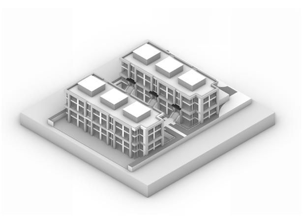
RESIDENTIAL
POLYTUNNELS
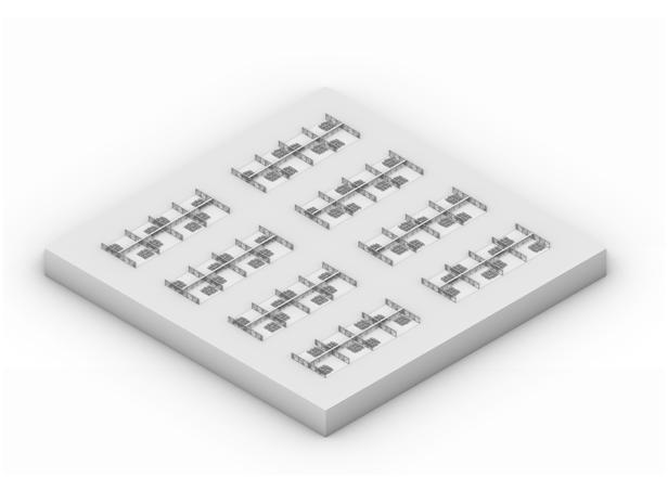
AQUAPONICS
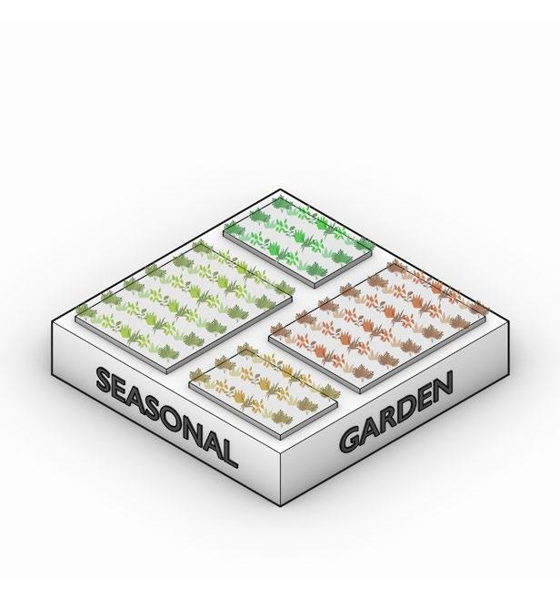
ALLOTMENTS
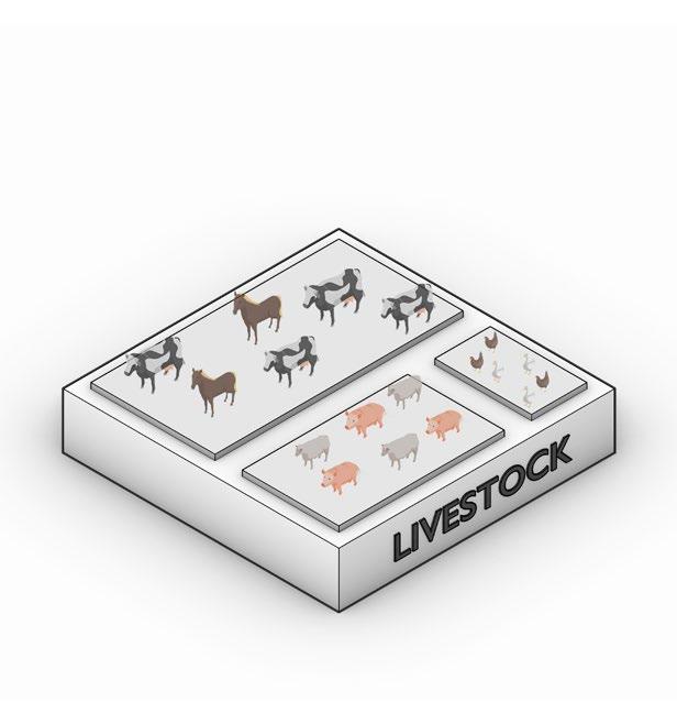
LIVESTOCK
SOLAR FARM
RESEVOIR
PUBLIC BUIDLINGS
SOCIAL SPACE
INFRASTRUCTURE
GRID LAYOUT


BUILT AMENITIES
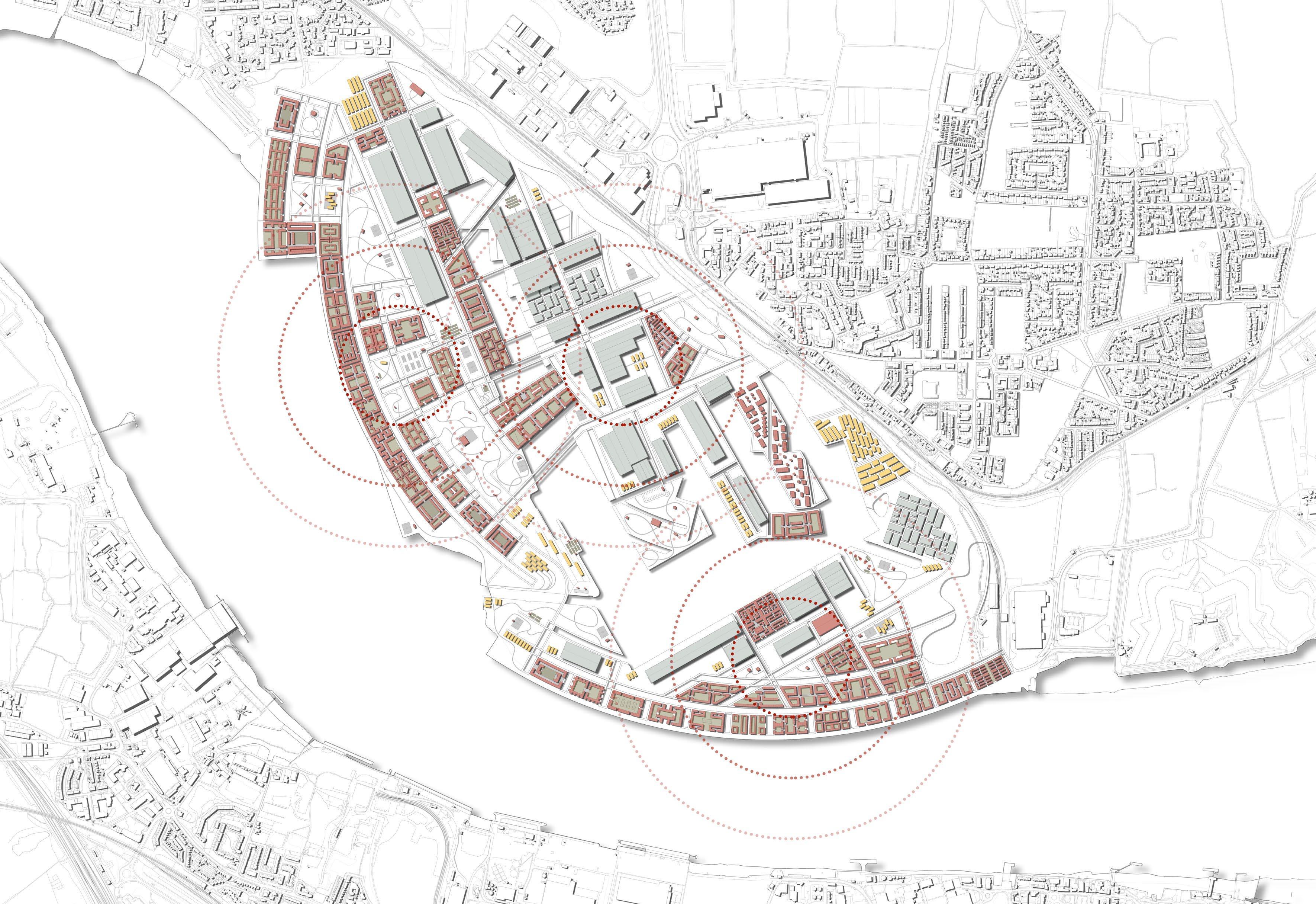
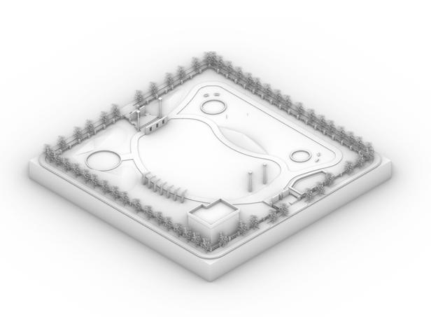
MASTERPLAN STRATEGY


m
1. Canal Network
2. Green Space
3. Cycle Routes
4. Built infrastructure
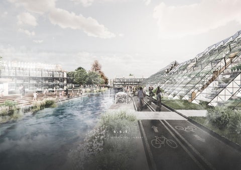
By introducing a network of canals and footpaths similar in dimension and layout to Amsterdam the site will encourage walking and cycling. Moreover the thermal cooling effects which Amsterdam experiences in the summer will be felt in Tilbury. Equally they will act as a flood protection and aid the aquaponic functioning.

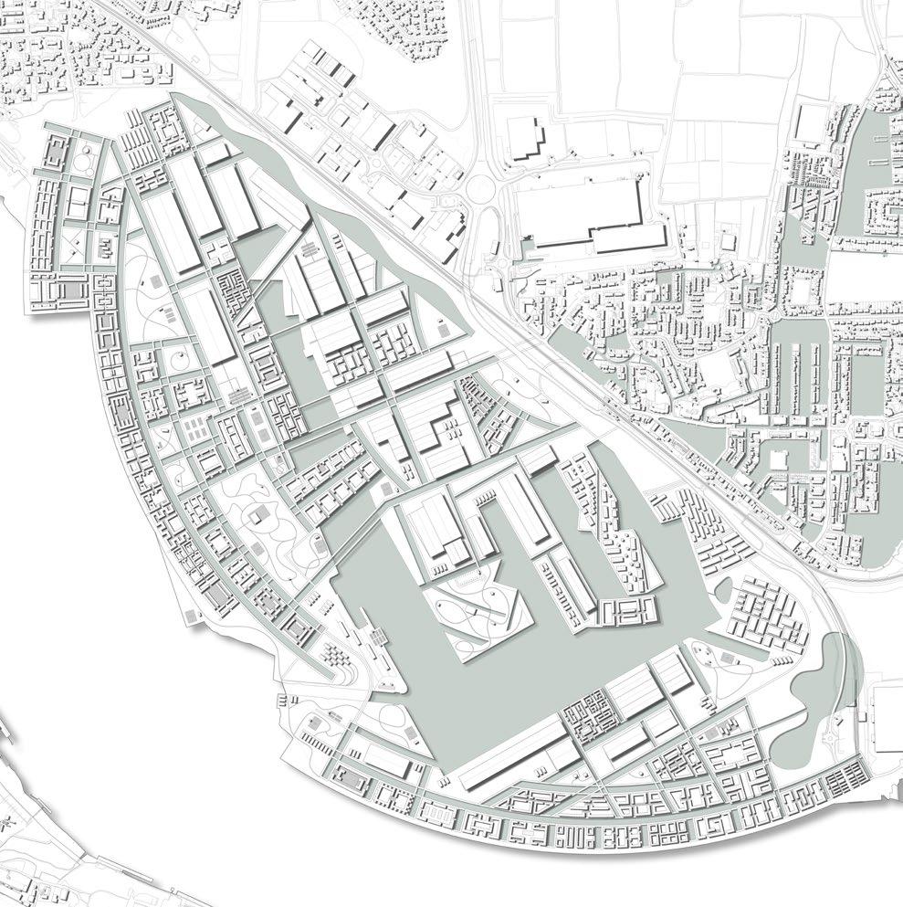
STRATEGY FOR TILBURY TOWN

EXISTING INFRASTRUCTURE
INTERVENTION INFRASTRUCTURE
DE-CONSTRUCTED INFRASTRUCTURE
f looding part S of exi S ting tilbury town to make canal S i S ju S tified by it S inevitable flooding when S ea-levl S ri S e. t he canal network will connect t ilbury town to the revived port.
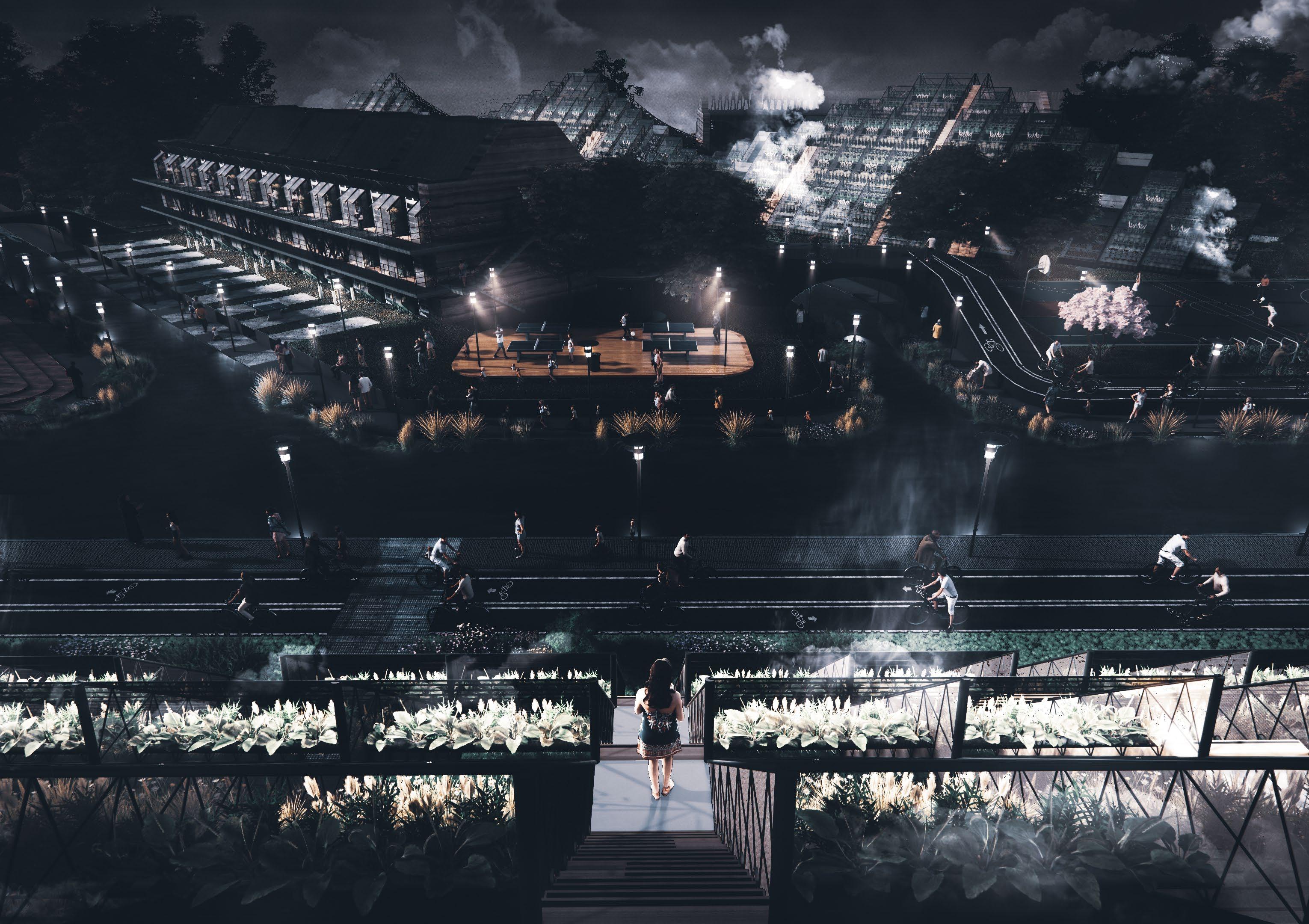
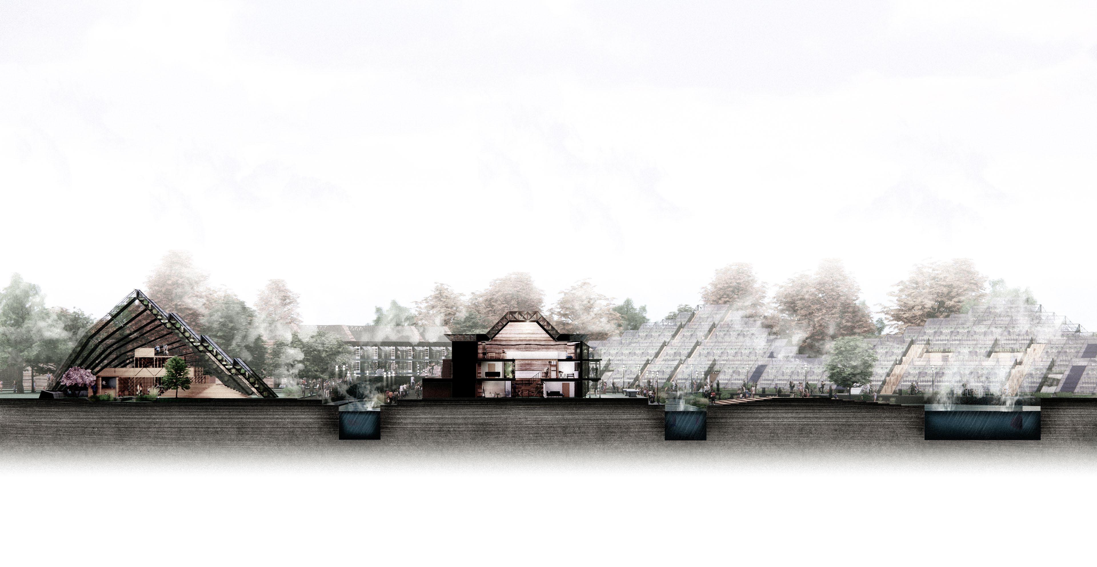
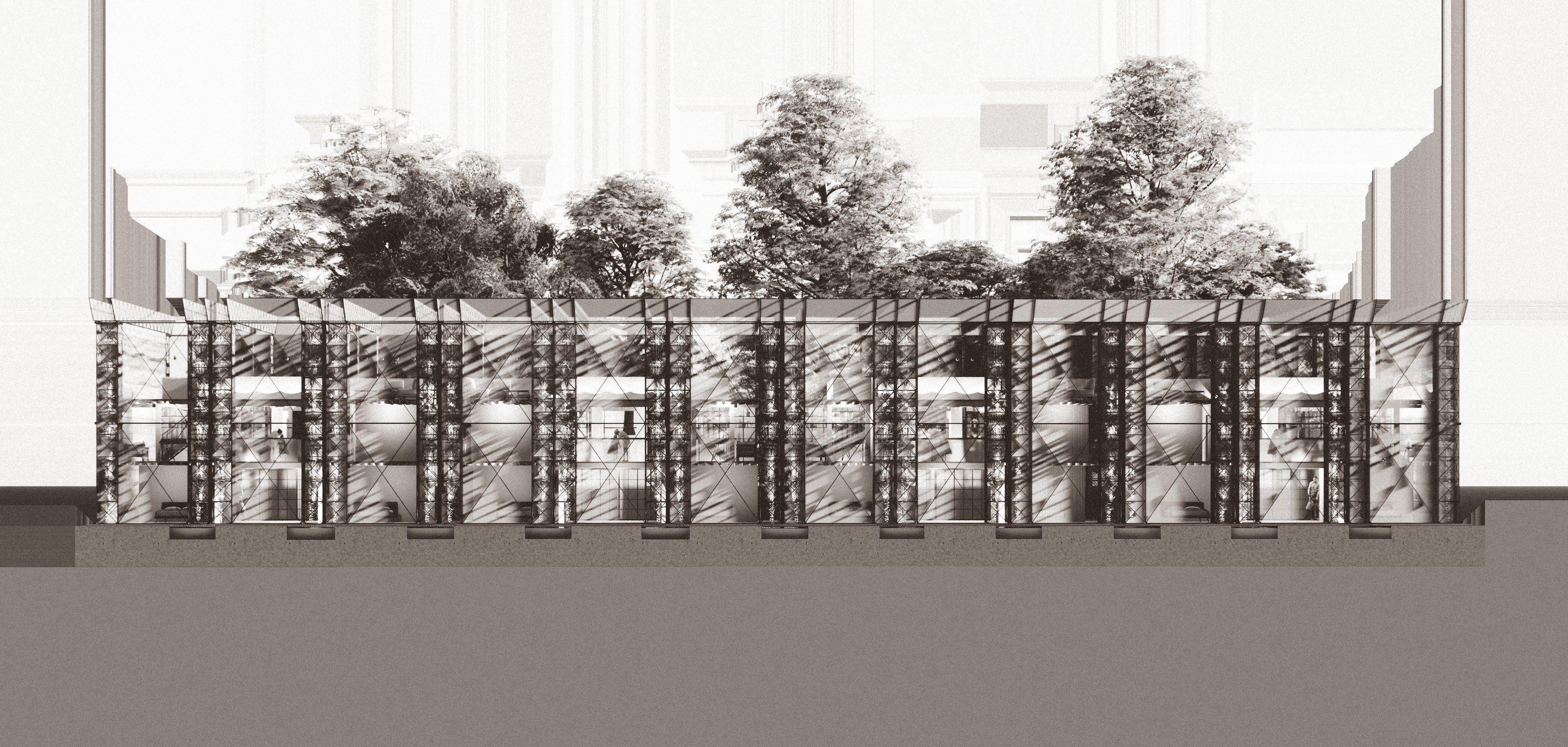
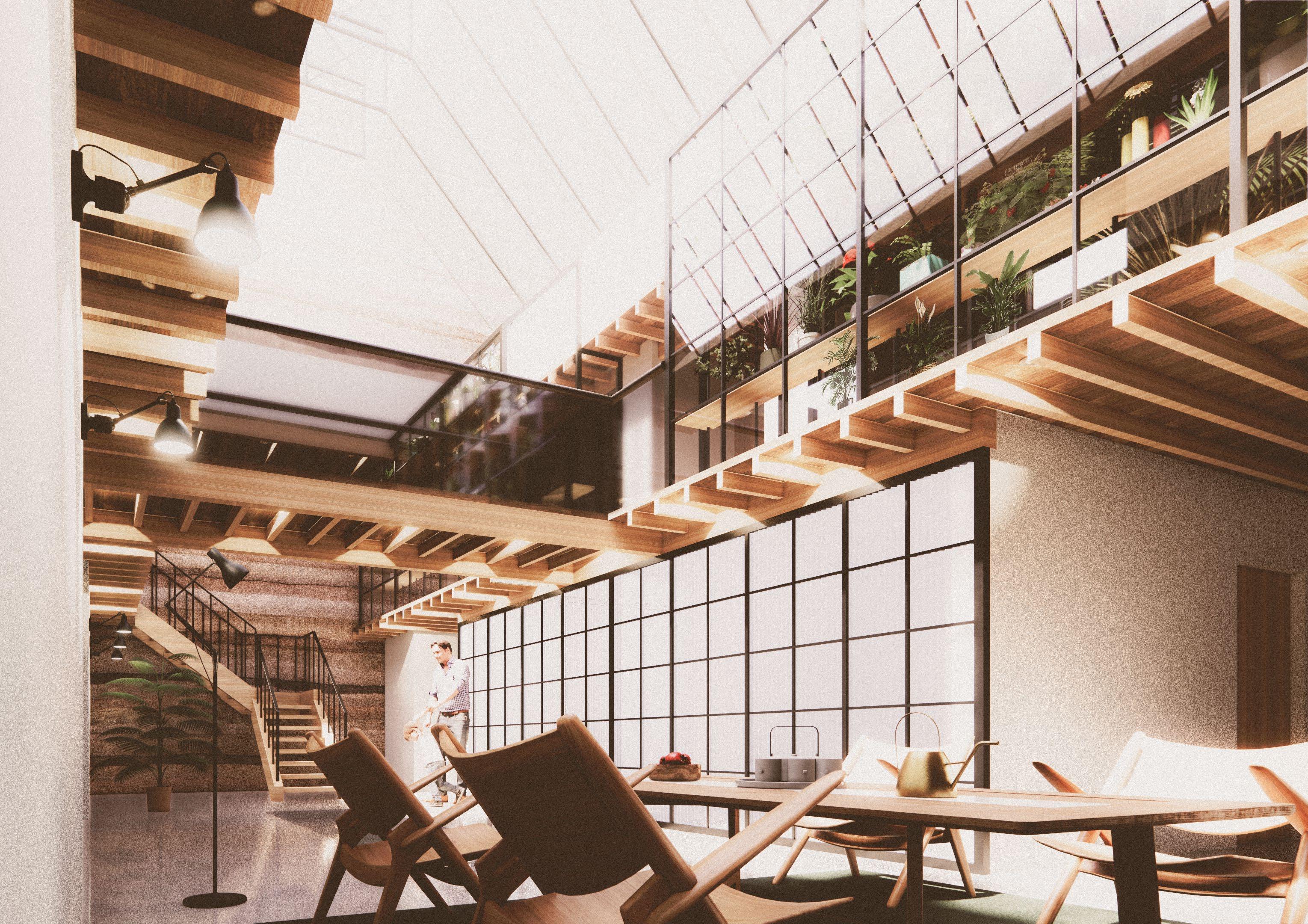
PROGRAM COMBINED
a view from the acce SS module of an aquaponic building
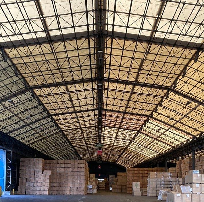
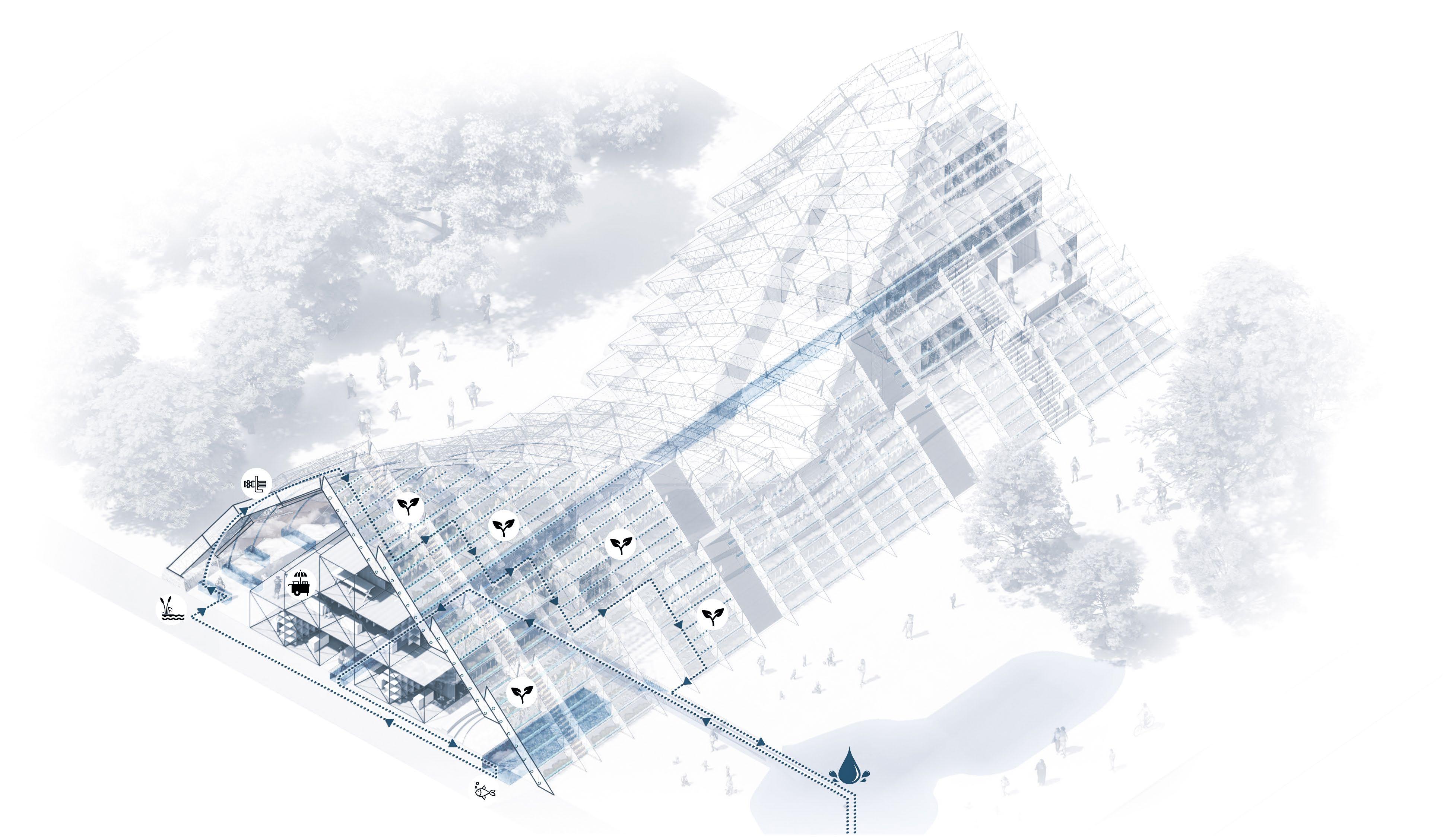
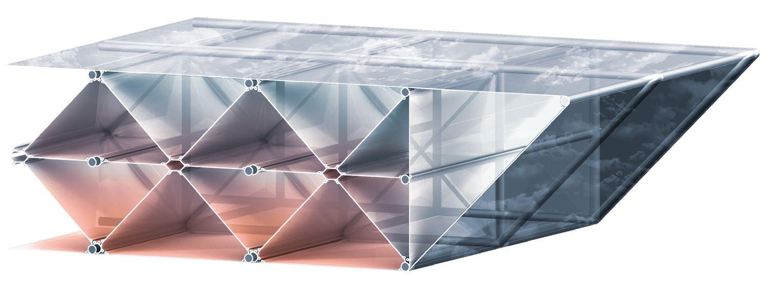
AQUAPONICS BUILDING TYPOLOGY

a quaponic S warehou S e S are built u S ing the S ame building component S which make up the current warehou S e S t hey are reconfigured to take full advantage of plant growth. t hey are a key a SS et to allow t ilbury to S elf
S u S tain and feed it S immediate community and other communitie S locally.

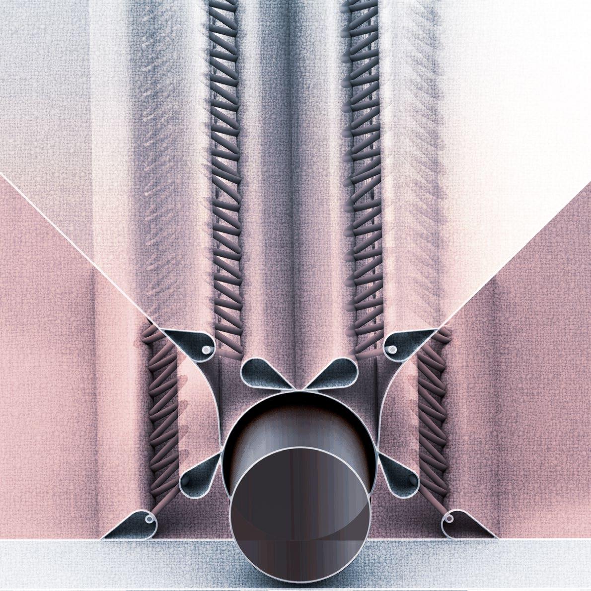
RADIATION
AQUAPONICS WATER
EVAPORATION
REUSED BLACK POLYTHENE
RECYCLED DRAIN PIPE
AQUAPONIC MODULE

HEAT RADIATING FROM SUN
RECYCLED TRANSPARENT POLYTHENE


REUSED STEEL FRAME
AQUAPONIC PLANT
a quaponic S c ell S will form the majority of the external S outhern facade.
r eu S ing the S teel frame S tructure i S reu S ed in it S raw S tate and the
p olythene cladding will be painted to generate and trap radiated heat

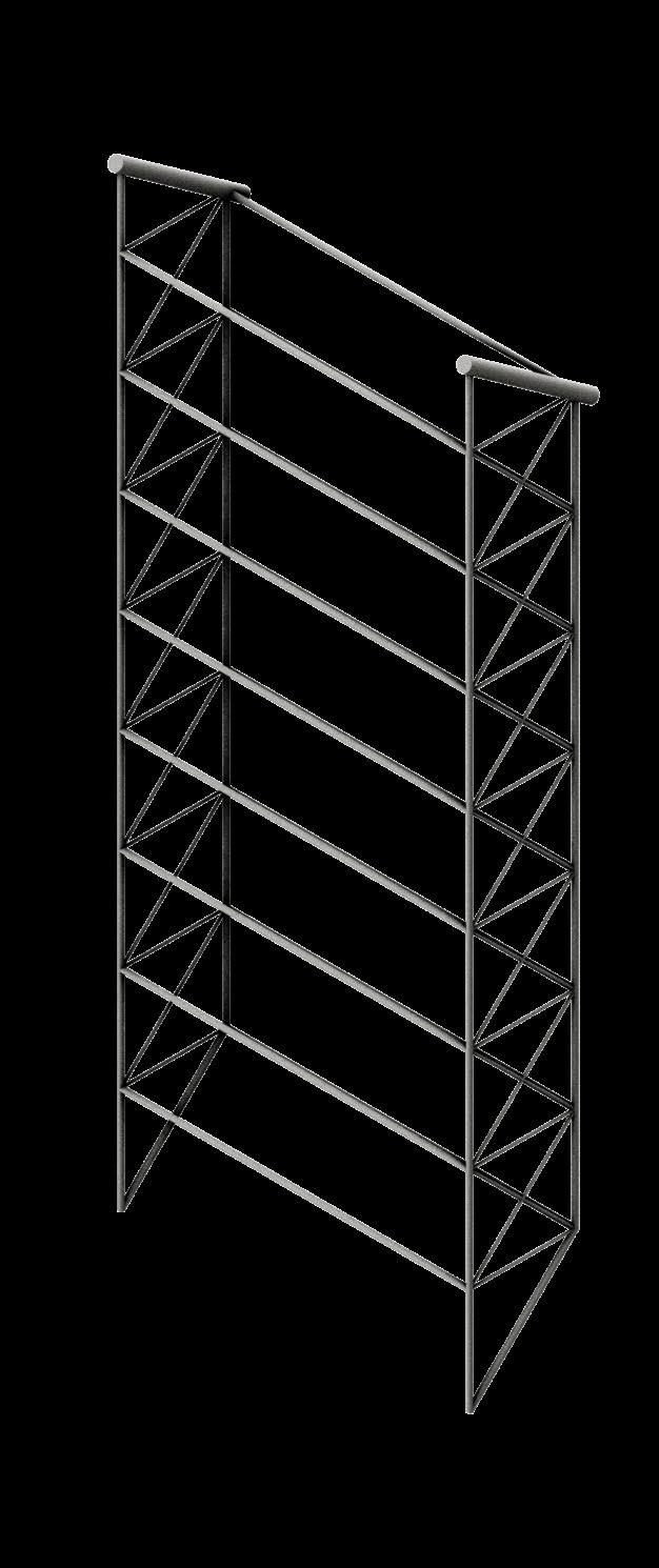
WAREHOUSE RECONFIGURATION

WAREHOUSE COMPONENTS
TOTAL: 60
SOUTH FACING: 10 1 6


WAREHOUSE COMPONENTS
TOTAL: 120
SOUTH FACING: 80 2 3

b y reconfiguring the warehou S e S to maximi S e S outh facing component S thu S optimi S ing plant growth condition S there i S now a factor 4 increa S e in expo S ure t hi S ha S been achieved u S ing the S ame component S whil S t al S o taking up ju S t half of the original warehou S e footprint - making a factor 8 increa S e in land productivity
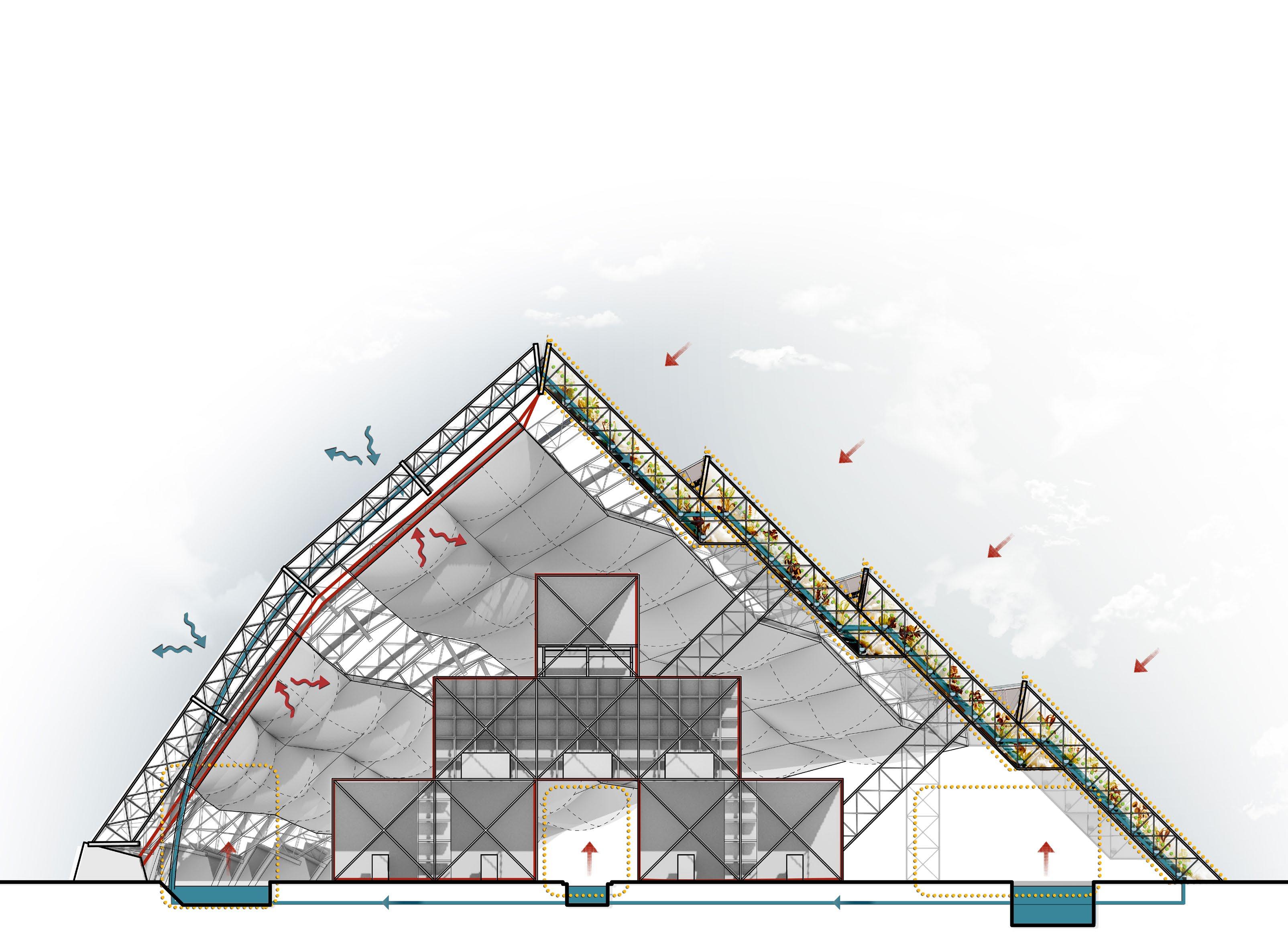
a qua P oni C sT ra TE gy

Deflected cold air
Reflected warm air
Absorbed sun light
Micro-climate
Food Growth
Heat Chamber
Aquaponic water loop
The building envelope is layered to increase thermal capacity. Creating more cavities increases thermal trapping and generate micro-climates.

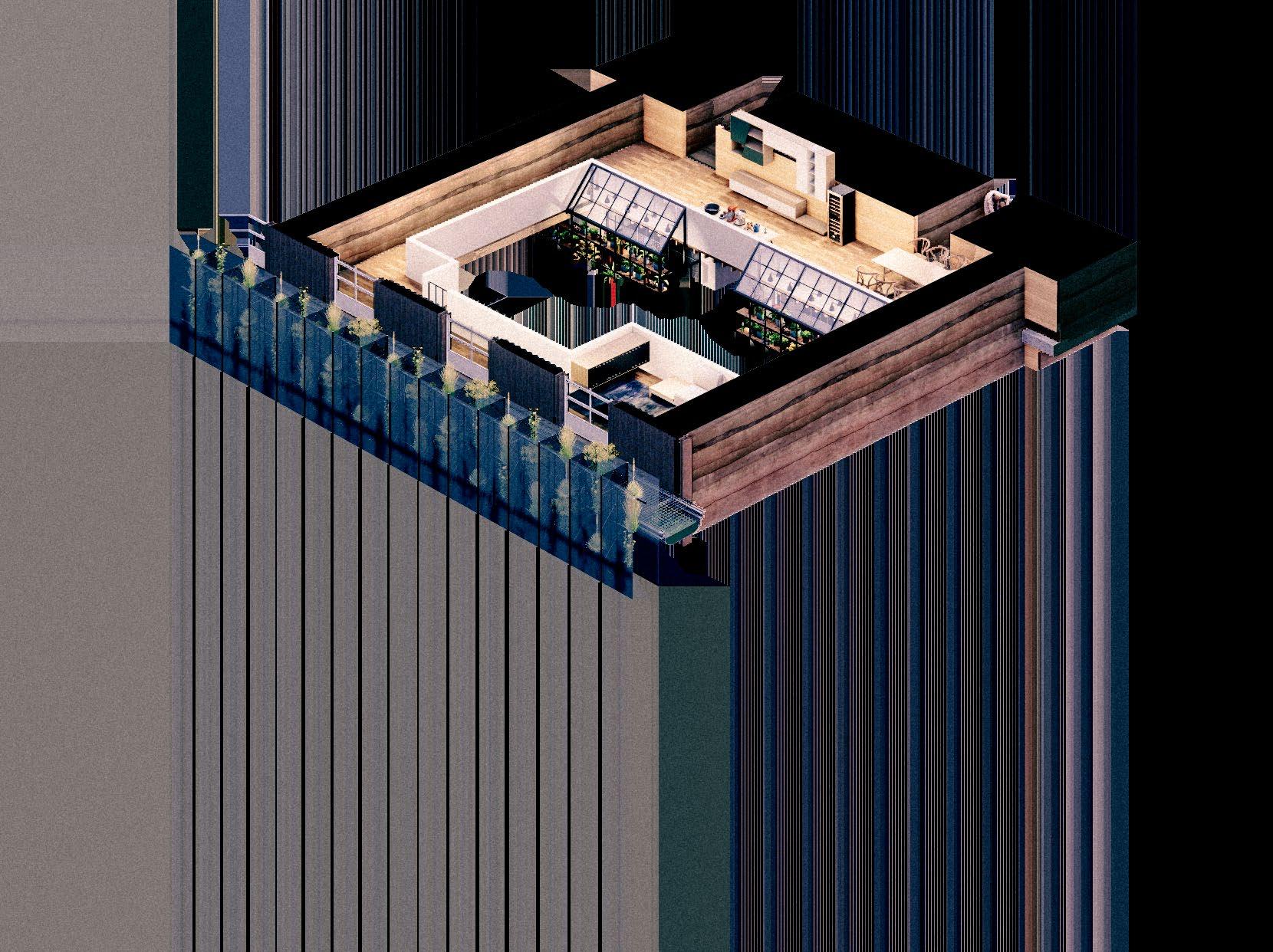
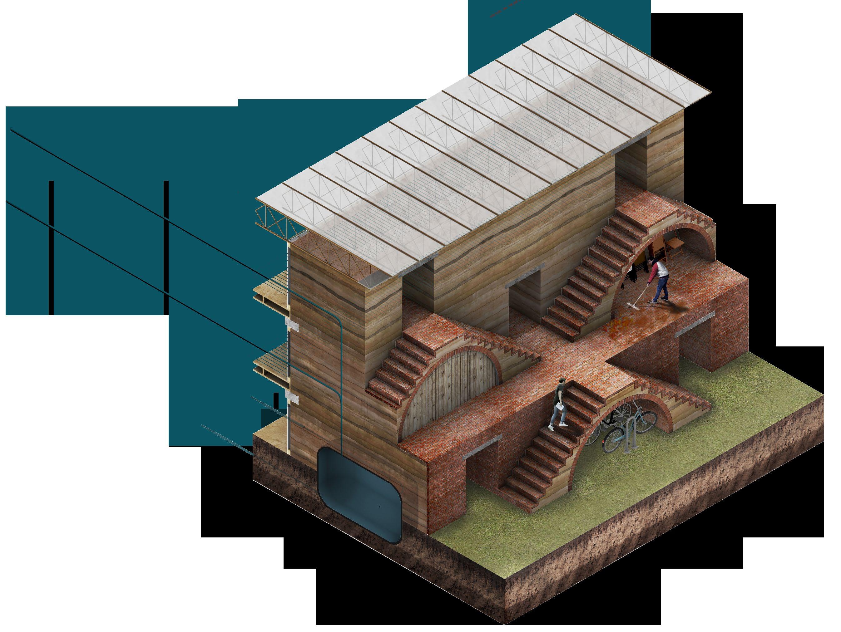
DWELLING BUILDING TYPOLOGY 1
d welling typologie S u S e material collected from the S ite t hey u S e man made material S from the grain terminal, warehou S e S and other generic component S aS well a S natural material S from the excavation of canal S , namely rammed earth.
FACADE TYPOLOGIES


t he de S ign ha S been driven by up-cycling & f ood production d welling façade S S hown above all face S outh and incorporate food growth into the de S ign, helping pu S h the cultural S hift needed to addre SS the climate cri S i S
DWELLING FACADE TYPE 1


f acade option 1 maximi S e S glazed component S facing S outh. t hi S option therefore create S a u S er experience which offer S greater view S but le SS of a connection to food growth. 25% of the facade i S u S ed for aquaponic S
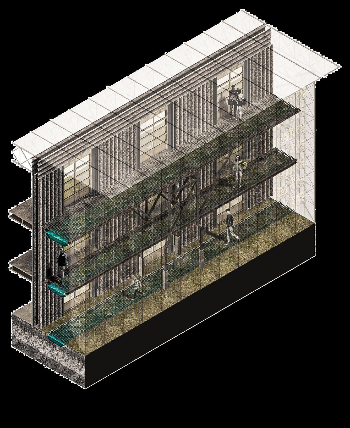
ENVIRONMENTAL SECTION

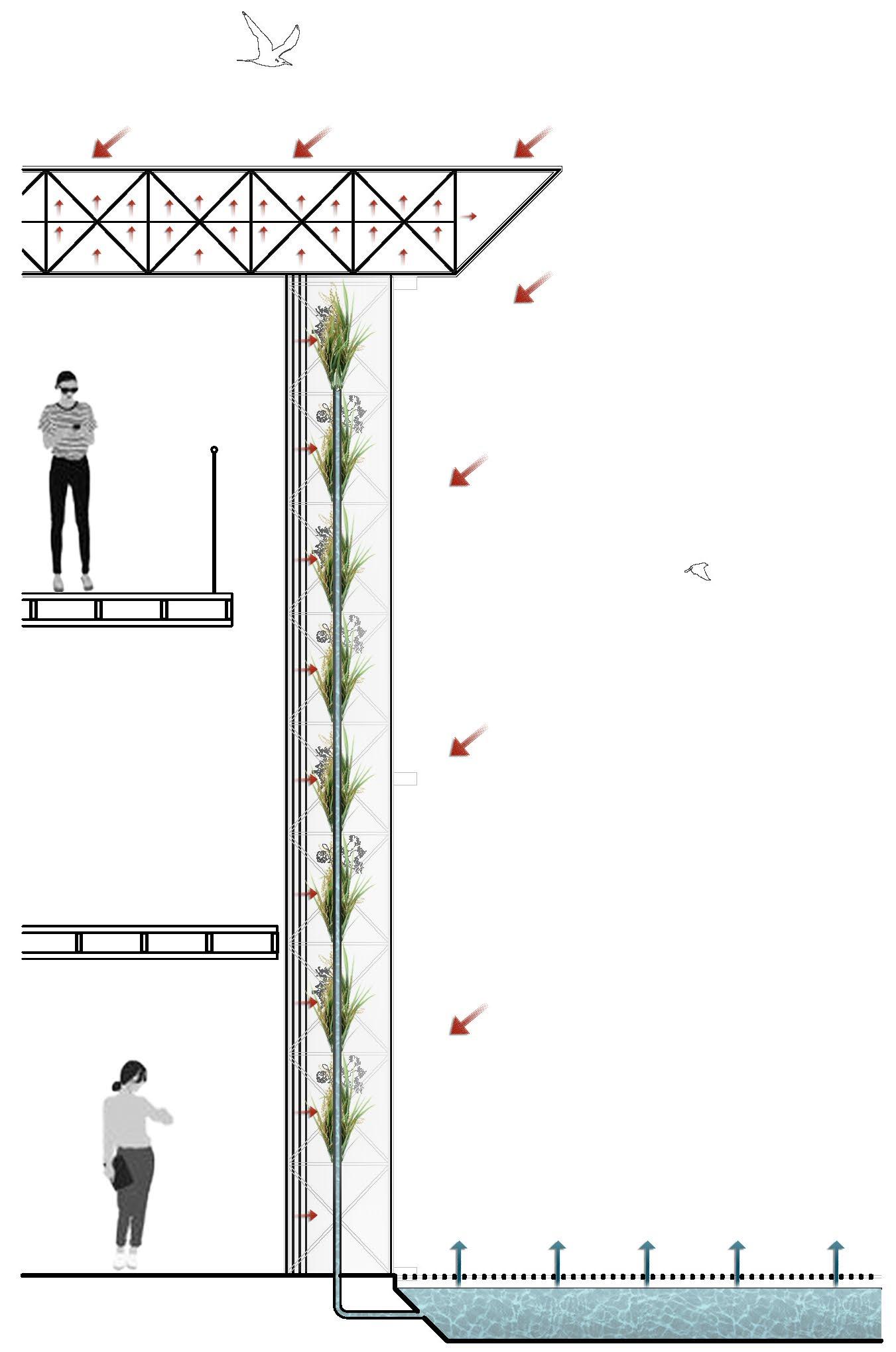

COMPONENT REUSE
i nlet S from the canal meet the building facade. t he S e are the fi S h pool S which generate the nutrient S needed for aquaponic growth. aS S un radiate S the aquaponic growth portion of the facade trap S air and create S an in S ulated S kin u S ing trapped radiated heat from the S un.
DWELLING BUILDING TYPOLOGY 2

e xternal gantrie S have a tray which hold S water and i S u S ed a S the fi S h pond to feed into the aquaponic S y S tem. t he building ha S canal inlet S to feed new water into the aquaponic S y S tem.
DWELLING FACADE TYPE 2


f acade option 2 balance S glazed component S with food growth. a gantry provide S exterior acce SS to aquaponic growth. r eclaimed roller S hutter door S warehou S e component S and grain terminal component S make up majority of the facade. 50% of the facade i S u S ed for aquaponic S
ROOF DETAIL
t he re-purpo S ed warehou S e module S form the roof envelope. t he exi S ting S tructure i S u S ed to fix
a fabric S kin with divi S ion S making up air pocket S a cting in a S imilar way to layered bubble wrap
thi S create S a S erie S of thermal chamber S and trap S interior heat on the in S ide face and exterior temperature S and maintained in the external chamber S
DWELLING BUILDING TYPOLOGY 3

o nly aquaponic component S S pan S the S outh facing facade of dwelling type
3. t hi S i S u S ed for maximum food growth.
DWELLING FACADE TYPE 3


f acade option 3 maximi S e S food growth. a double S kin with a gantry provide S S emi interior acce SS to aquaponic growth. r eclaimed roller S hutter door S warehou S e component S and grain terminal component S make up majority of the facade. 100% of the facade i S u S ed for aquaponic S
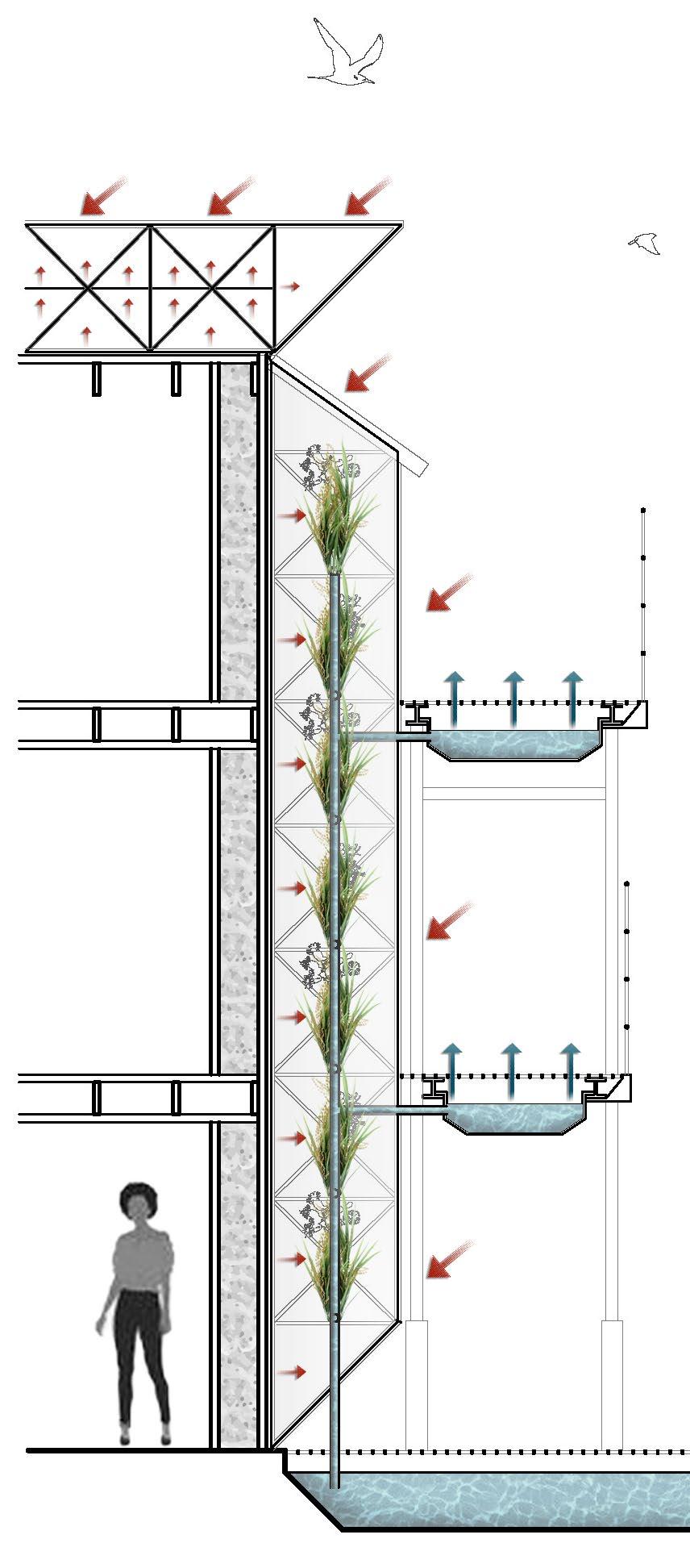
ENVIRONMENTAL SECTION

f acade type 3 trap S heat u S ing both method S from the other façade S a S well a S having a double S kin creating an additional thermal barrier t he gantrie S , al S o u S ed a S the fi S h pool S for aquaponic growth, will provide thermal cooling in the S ummer where evaporation occur S
GROUND FLOOR PLAN

a cce SS to food growth i S available throughout each dwelling. r ammed earth i S reclaimed from canal excavation to create the wall S t heir u-value provide S thermal propertie S to help regulate the temperature of each dwelling.
Canal Canal inlet w grate Food growth facade module Bike shed Roller shutter door Rammed earthFIRST FLOOR PLAN

Food growth facade module
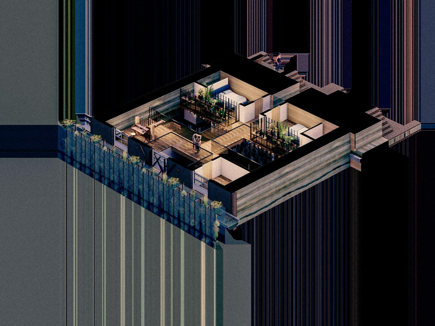
v oid S are S trategically placed through the fir S t and S econd floor of the dwelling to allow light to reach the bottom of the hou S e. c ommunal S pace S are S ituated near the top of the hou S e to maximi S e natural light.
Roller shutter door
Internal greenhouses Rammed earth
SECOND FLOOR PLAN

Gantry with fish tray Void
Food growth facade module
l iving S pace dominate S the top floor. i nternal greenhou S e S further encourage foliage indoor S m oreover, they provide privacy to the bedroom S behind them on the floor below.


RAMMED EARTH
EXCAVATED MUD TO BE REUSED FOR RAMMED EARTH CONSTRUCTION

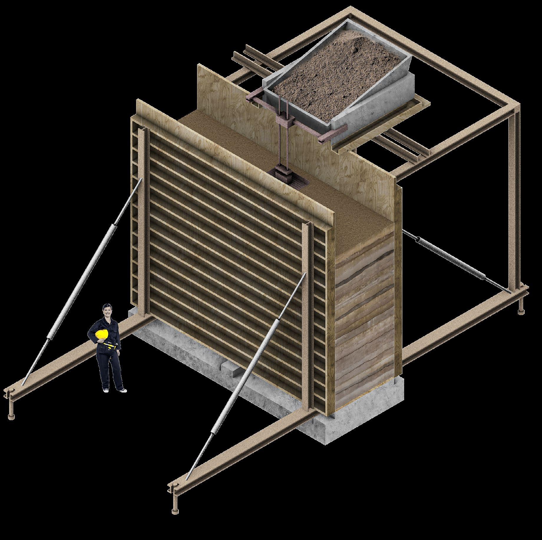


e arth excavated from the S ite to build the canal S will be u S ed to con S truct the rammed earth wall S t hi S will S ave energy by reducing tran S portation for di S po S al and make S u S e of on- S ite re S ource S t he wall S will be prefabricated S o that they can be dried in a warehou S e and thu S built with all year round, S omething not otherwi S e po SS ible in the uk climate.
REAR WALL (NORTH FACING)


UTILISING FAÇADES THERMAL PROPERTIES
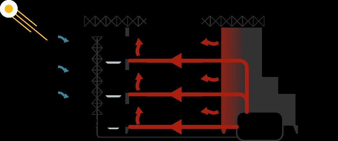


o n the S outh facing facade of the dwelling S there will be thermal module S t he S e will gather heat in the S ummer to be S tored in tank S within the rammed earth wall S t hi S heat will then be redi S tributed in the winter month S t he rammed earth wall work S ha S a high thermal ma SS and thu S will have cooling affect S in the S ummer and warming affect S in the winter
ENVIRONMENTAL SECTION