PORT f O li O
felix chan
architectural designer


MAYFLOWER MOUNTAIN RESORT VICEROY X CIRQUE


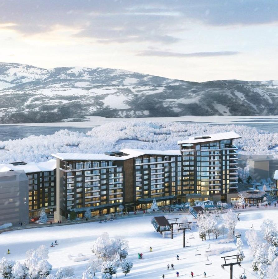
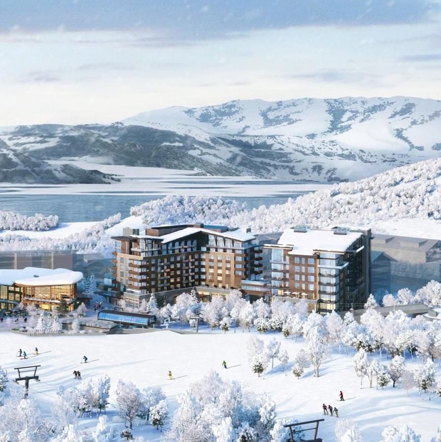
Mayflower Mountain Resort is a newly developed luxury alpine village in Wasatch County, Utah. The project includes ~100 luxury condominiums and two hotels at the base of the mountain.
Square footage for the project amounts to 1 million square feet with a 320,000 SF Podium with a 172,000 SF Hotel above it, a 205,000 SF Condo Building, and a 437,000 SF building with a Designer Hotel and Condo combination.
Individual responsibilities within the project included:
• Participated throughout SD, DD, and CD phase
• Accessible code requirements (ADA & ANSI) for all hotel, condo, as well as public spaces.
• 30+ Stairs and Elevators to satisfy IBC requirements
3 UNIT PLAN - NORTH HOTEL PRESIDENTIAL SUITE - L 10 ACC
2 UNIT PLAN - NORTH CONDO - UNIT D ACCESSIBILITY

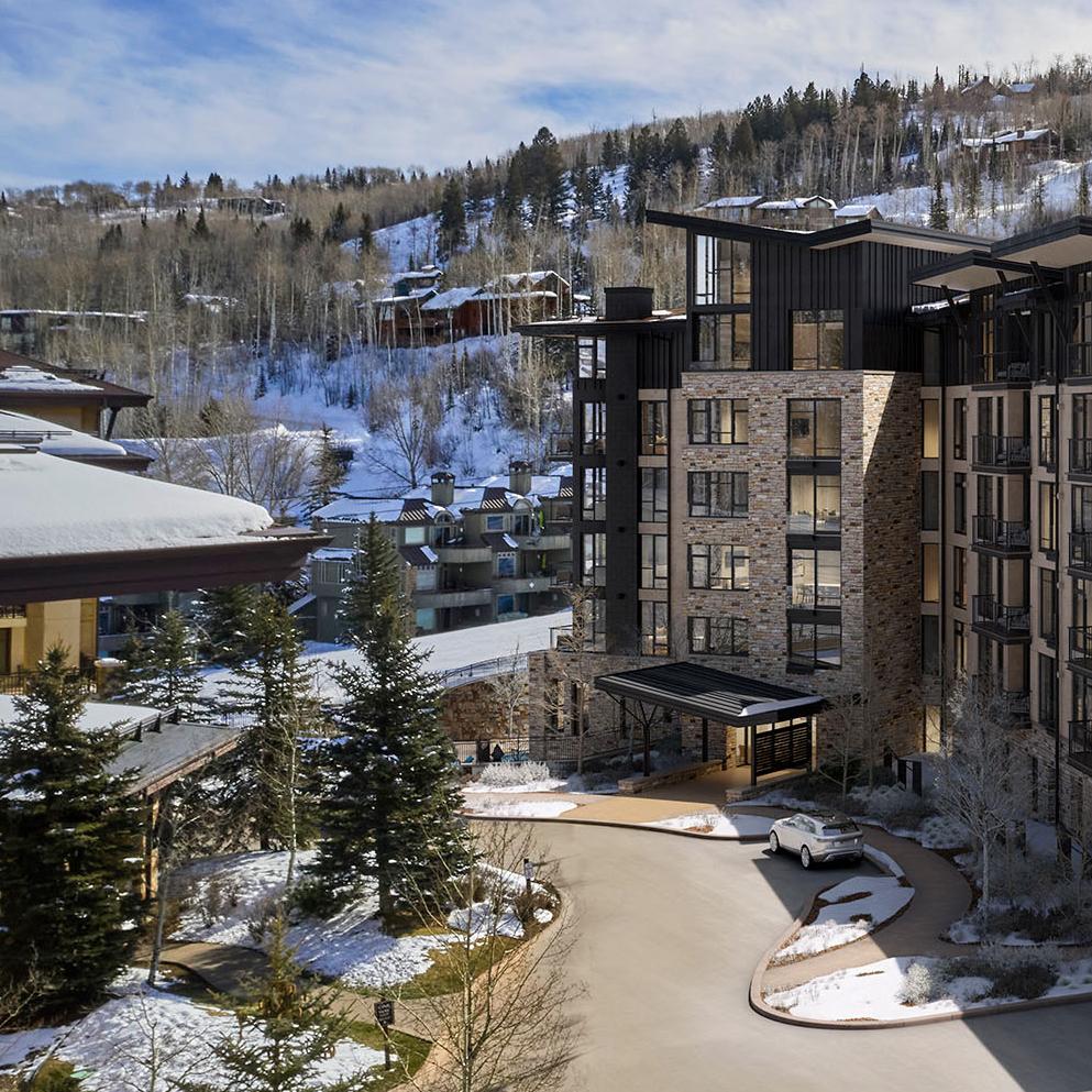
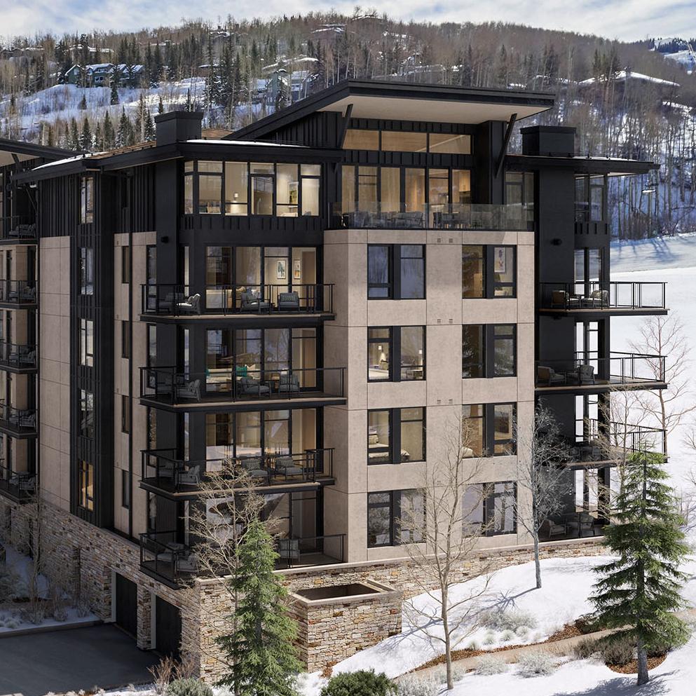
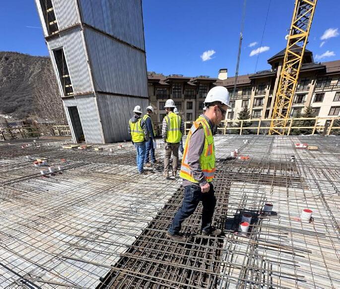
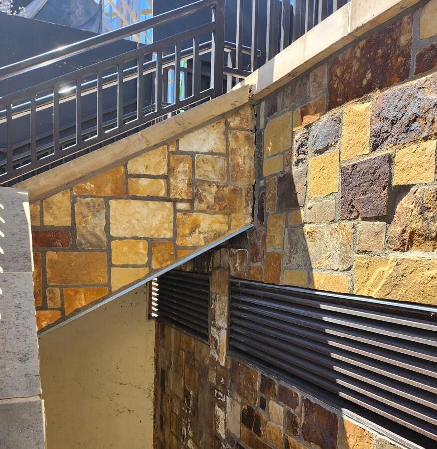
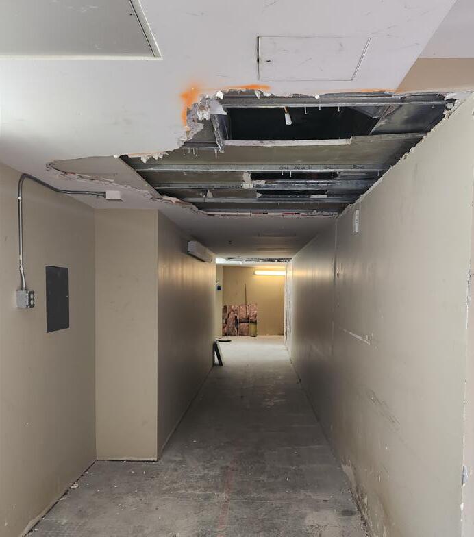
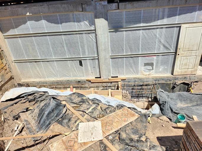
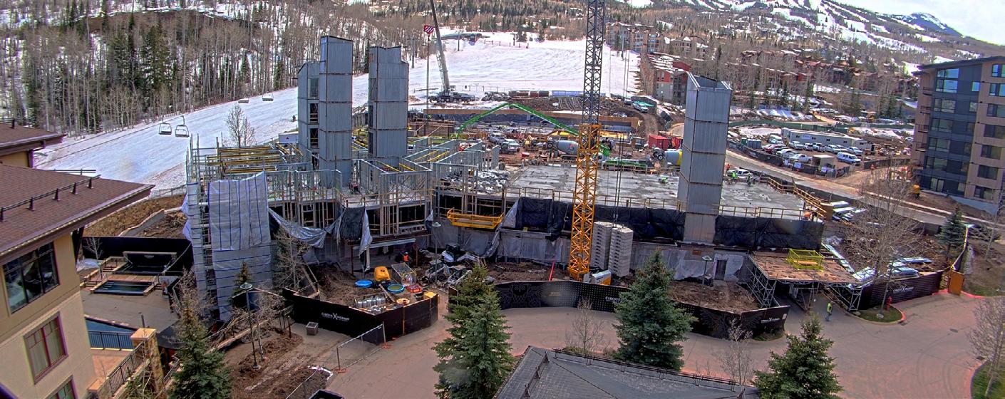
Viceroy x Cirque is currently in construction in Pitkin County, Aspen, Colorado. This luxury condo building have 40+ units providing ski-in/ski-out to the nearby ski trail to the east. The building is constructed as a topping to an existing parking garage structure built 15 years ago.
Individual responsibilities within the project included:
• Participated throughout CA phase
• Assisted with RFIs, Submittals, and ASIs
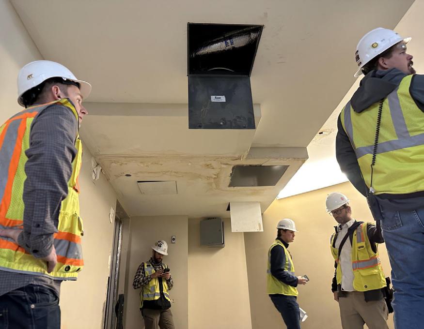
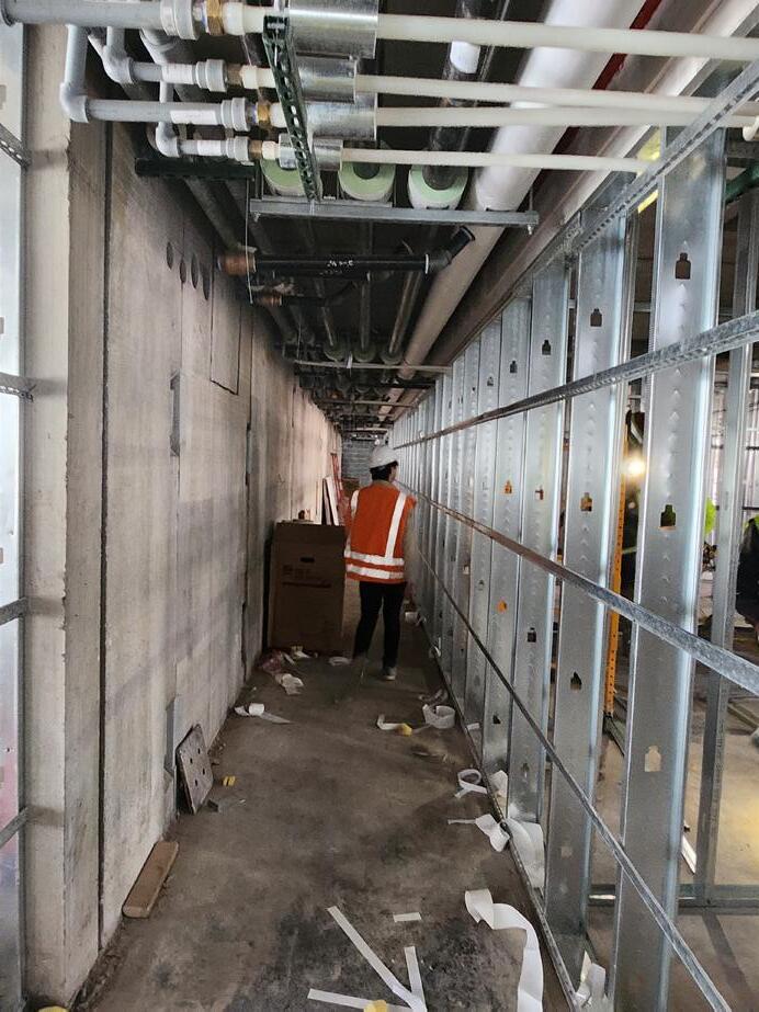
• Went on site visits to coordinate with GC (Haselden Construction) and consultants
• Assisted with site observation reports
• Documented all changes to plans and frequently updated drawing set via Newforma Document Control
• Attend OAC meetings and BIM Coordination meetings


 COLLABORATION WITH JACOB POEHLS AND JIMMY NGUYEN
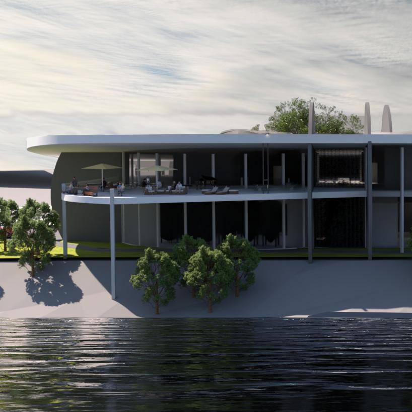
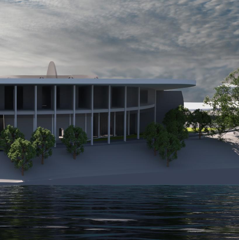
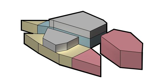
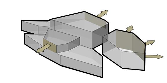
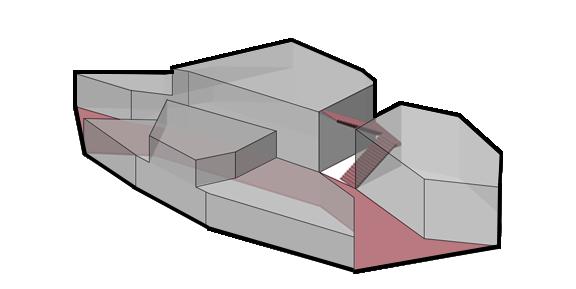
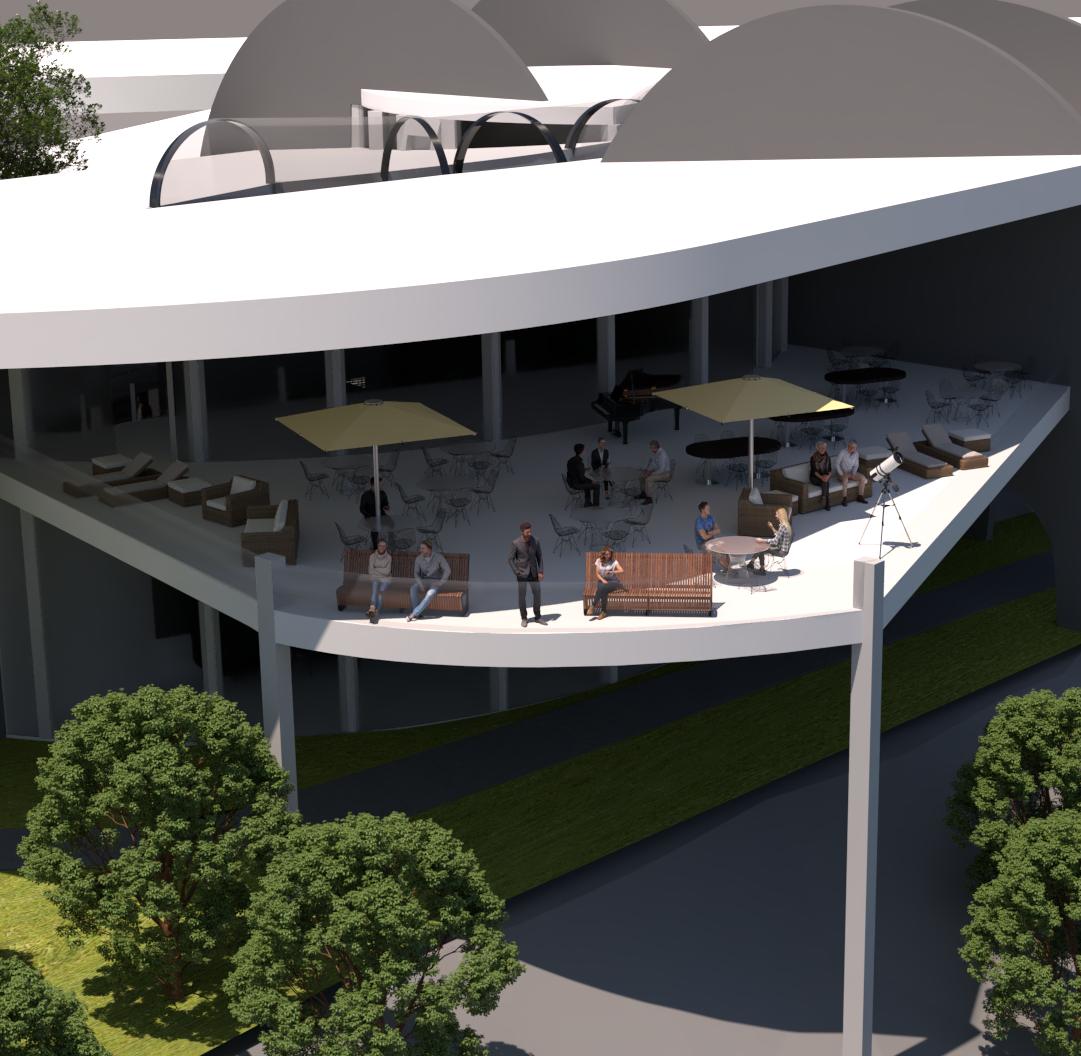
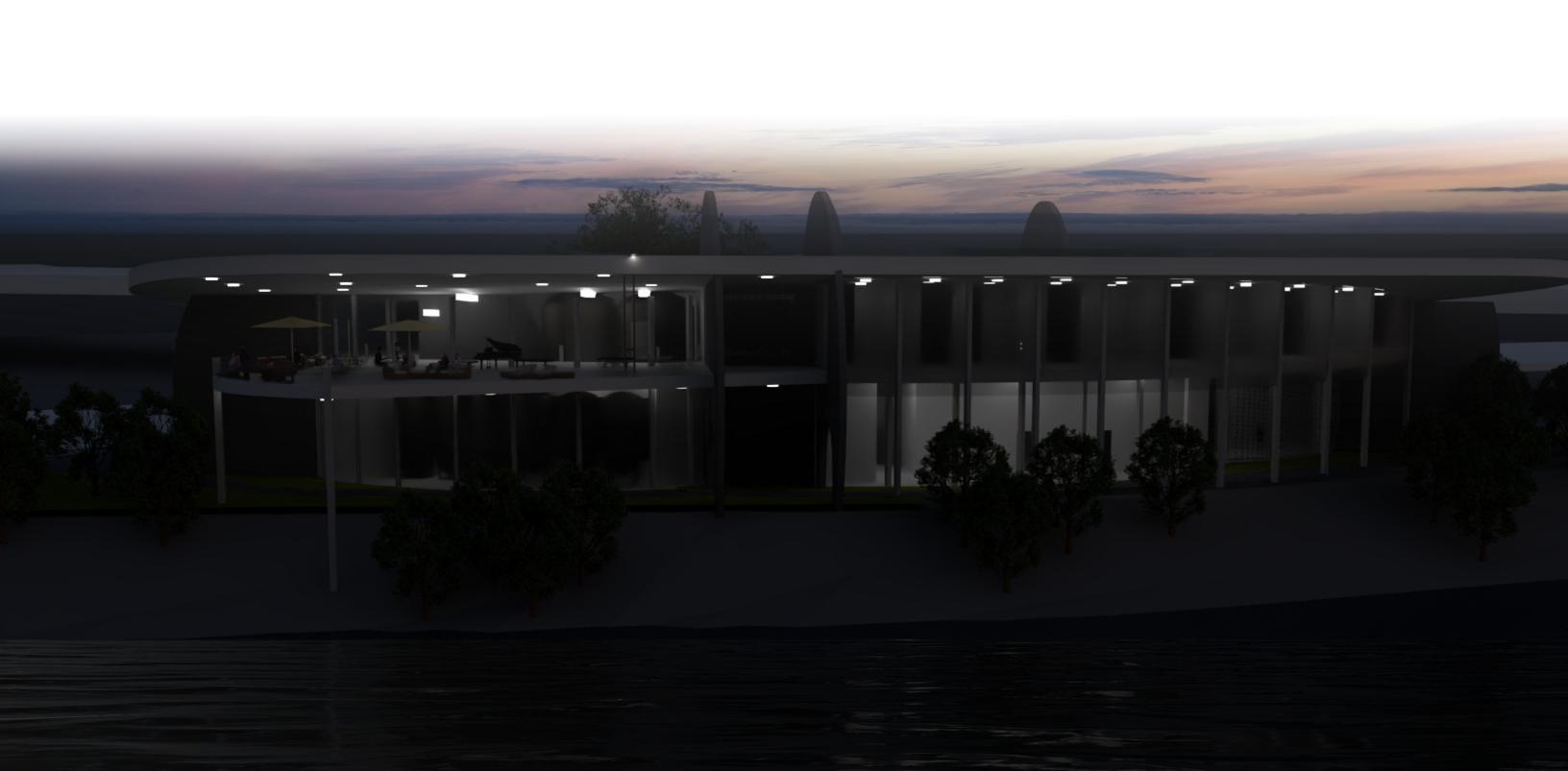
PASS || THROUGH is a design that holds a double meaning. It encourages human circulation throughout its passageways and also captures wind movement through the building’s facade.
This project addresses the concept of Work/Live Architecture once again, but rather than having a separated housing, we explored how a single structure would develop.
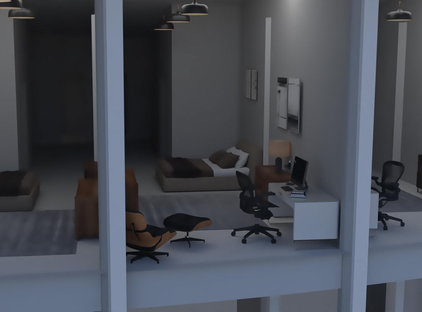
The parti of the design focuses on a shared living situation with individual rooms paired with a communal kitchen and living room area. These rooms are on the upper level while the lower level is for visitors and guests.
As the site is located on a heavy foot traffic area, ingress and egress are placed in locations visible to the sidewalks to encourage visitation into the space.
BREWER
LANDSCAPE DESIGNER
WELDER
COMMUNAL LIVING SPACE
PEDESTRIAN TRAFFIC
WINDOWS
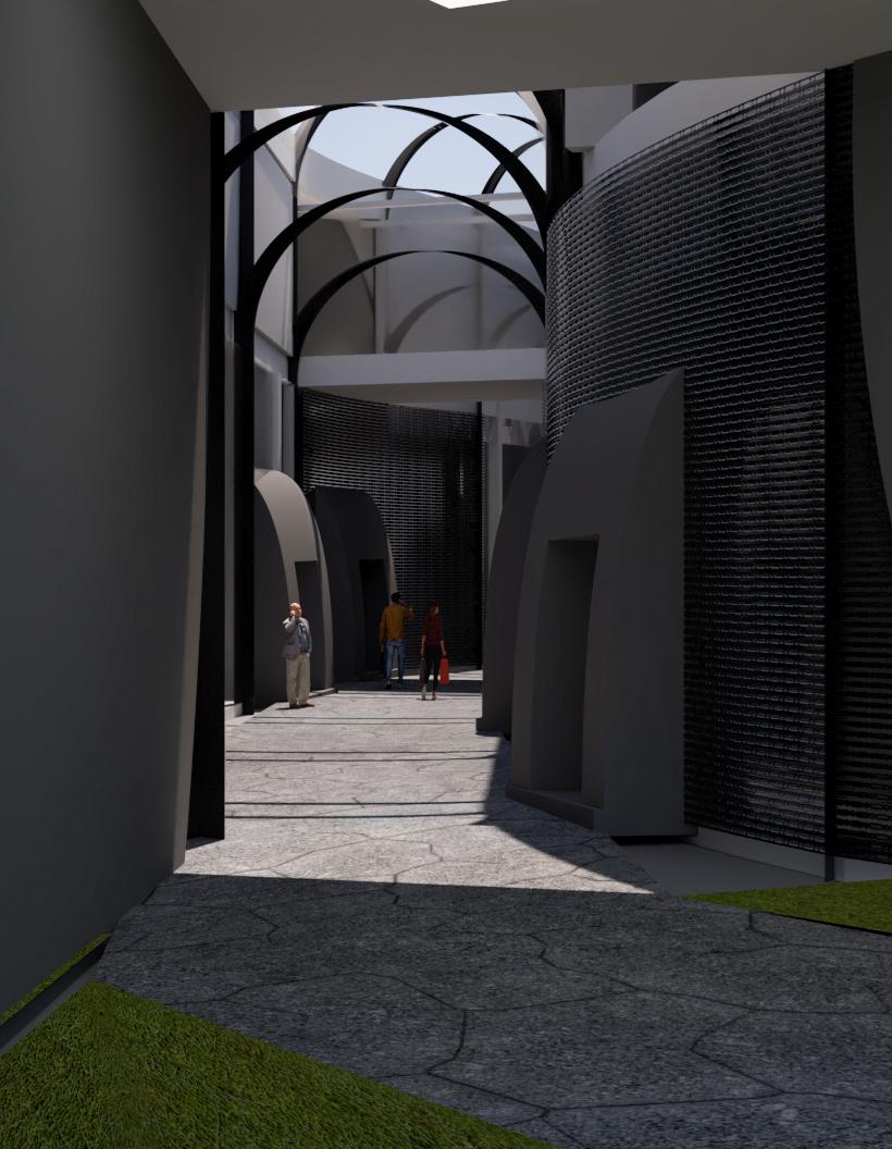

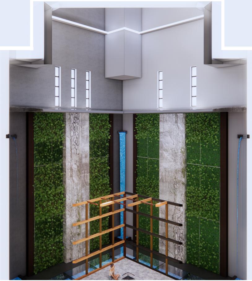
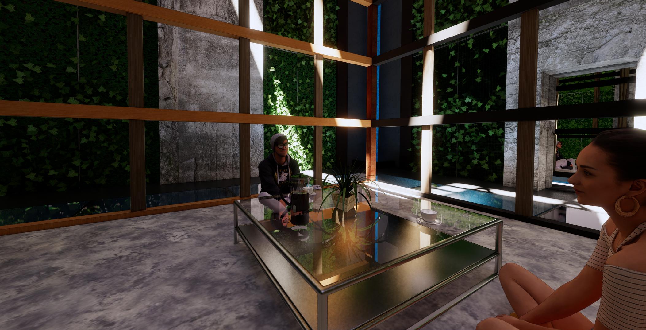
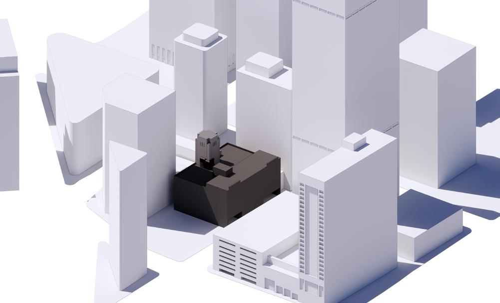
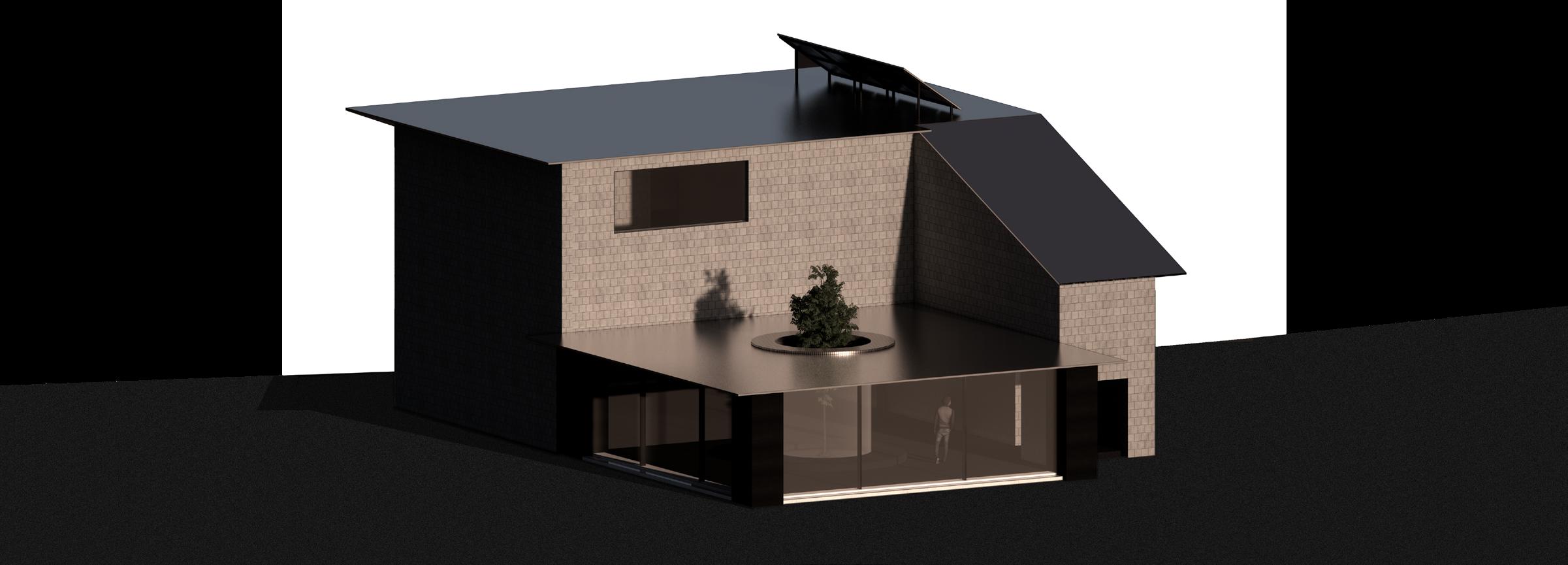
The Tea House is a project focused on an interior redesign of an abandoned water tower in the heart of downtown Denver. It sits upon an abandoned bus depot that used to be Denver’s central hub of transportation.
Nowadays, the site is a commonly overlooked building in the city, the concept of the tea house focuses on creating a hidden paradise within the chaos of the busy city life.
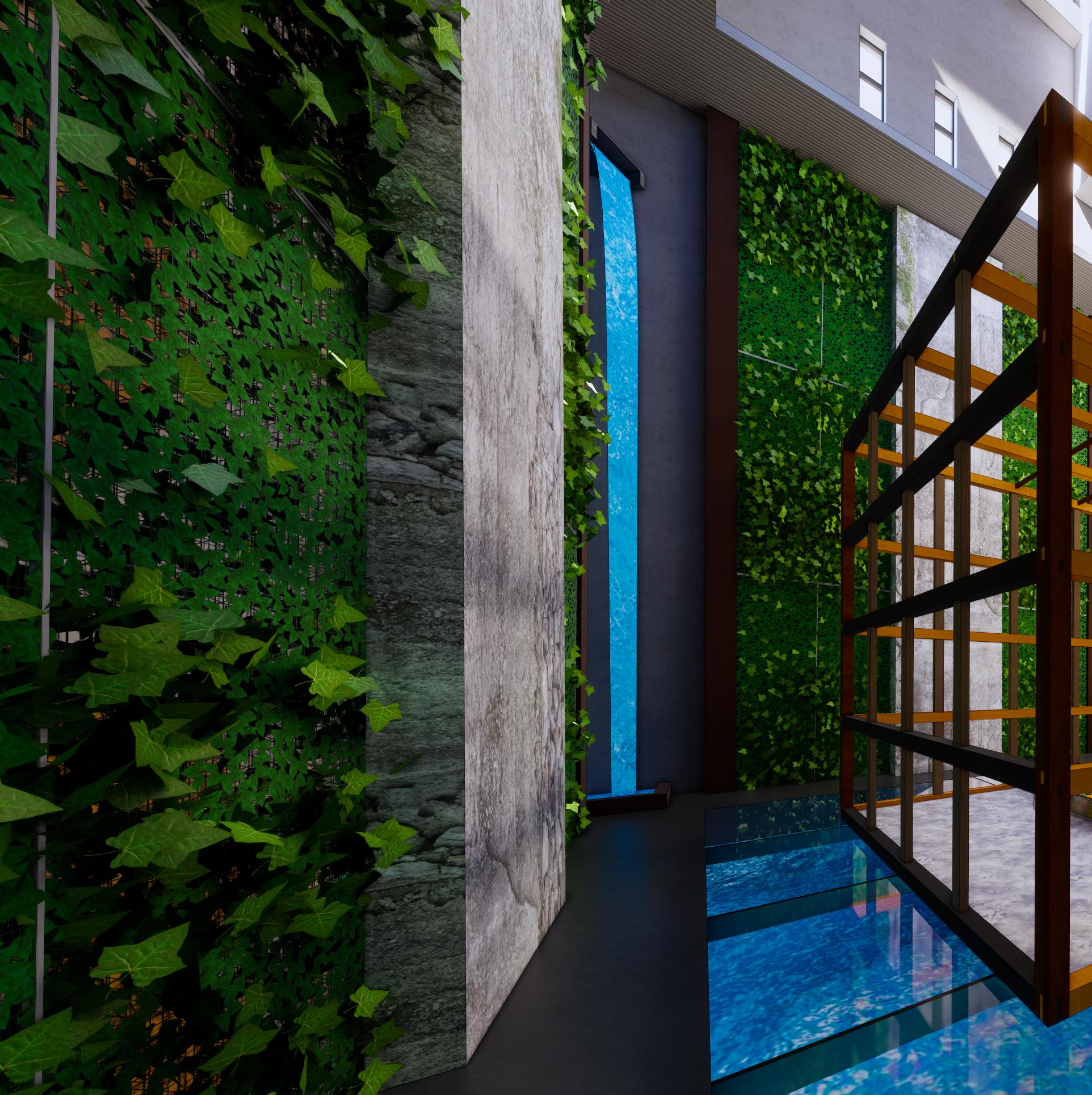
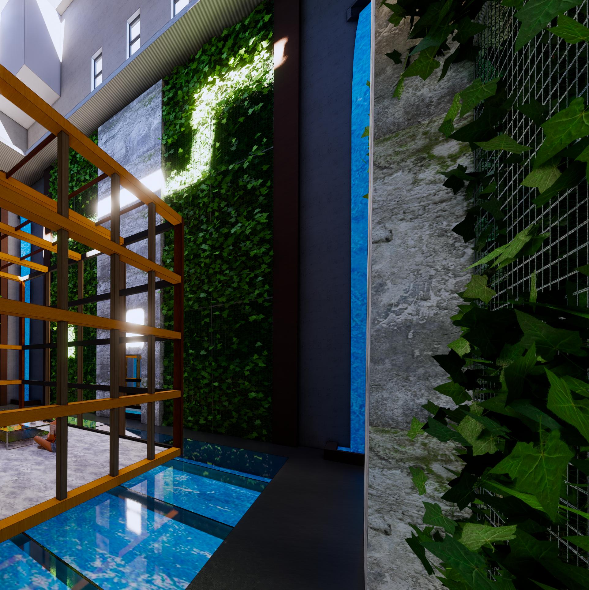
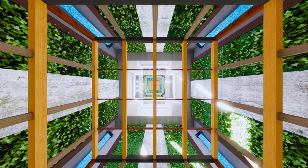
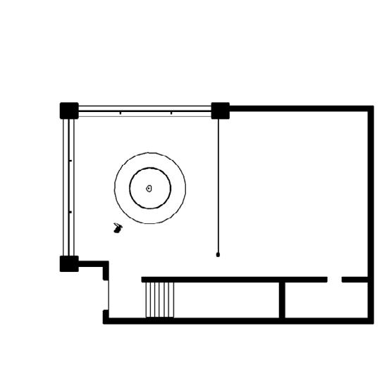
Many of its aspects tie back to traditional Japanese tea houses and their senses of tranquility and self reflection. Ranging from a modern adaption of a Koi Pond to the traditional wood joinery found in many older Japanese structures, this building combines both new and old design techniques.
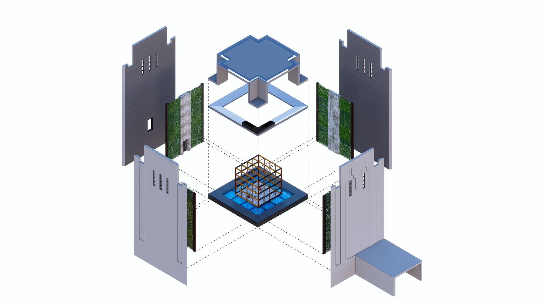
The design can be simply divided into three sections.
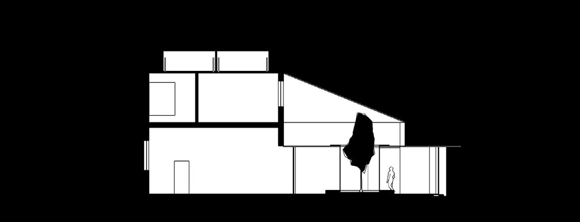
The Lightbox, which distributes an even coat of indirect lighting throughout space through the use of a mirror system reflecting light across multiple directions. This is complimented with strong slashes of direct light that directly hit the lower regions at certain times of day.
The Cube below acts as a metaphorical barrier allowing the user to bring the focus back onto themselves and avoid being overwhelmed the vertical scale of the building.
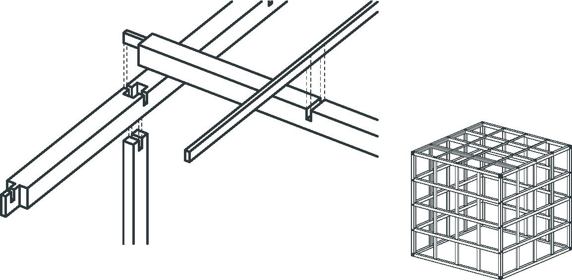
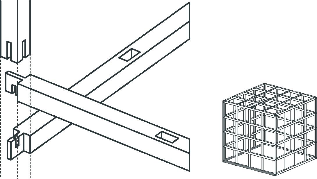
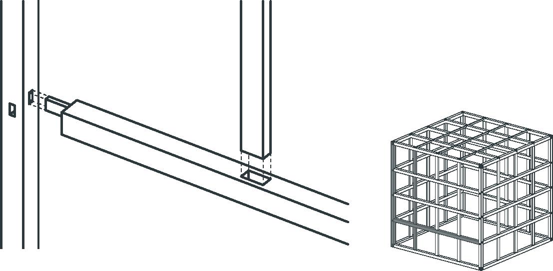 CEILING JOINT
RIB JOINT
CEILING JOINT
RIB JOINT

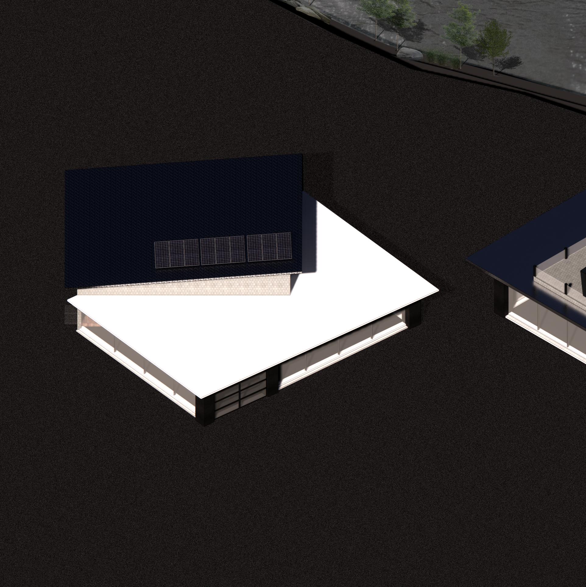
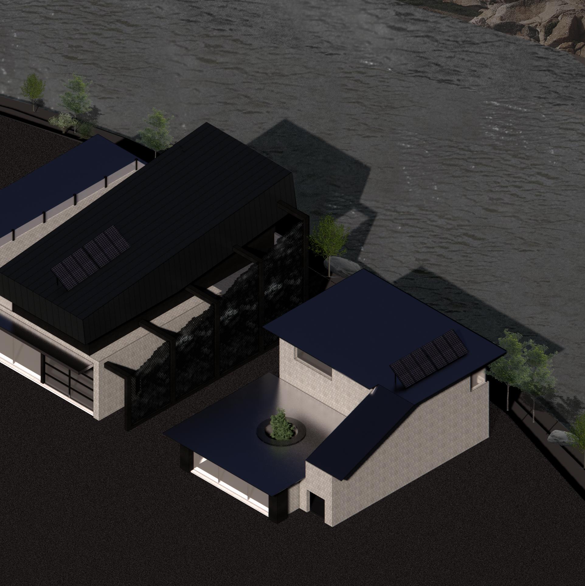
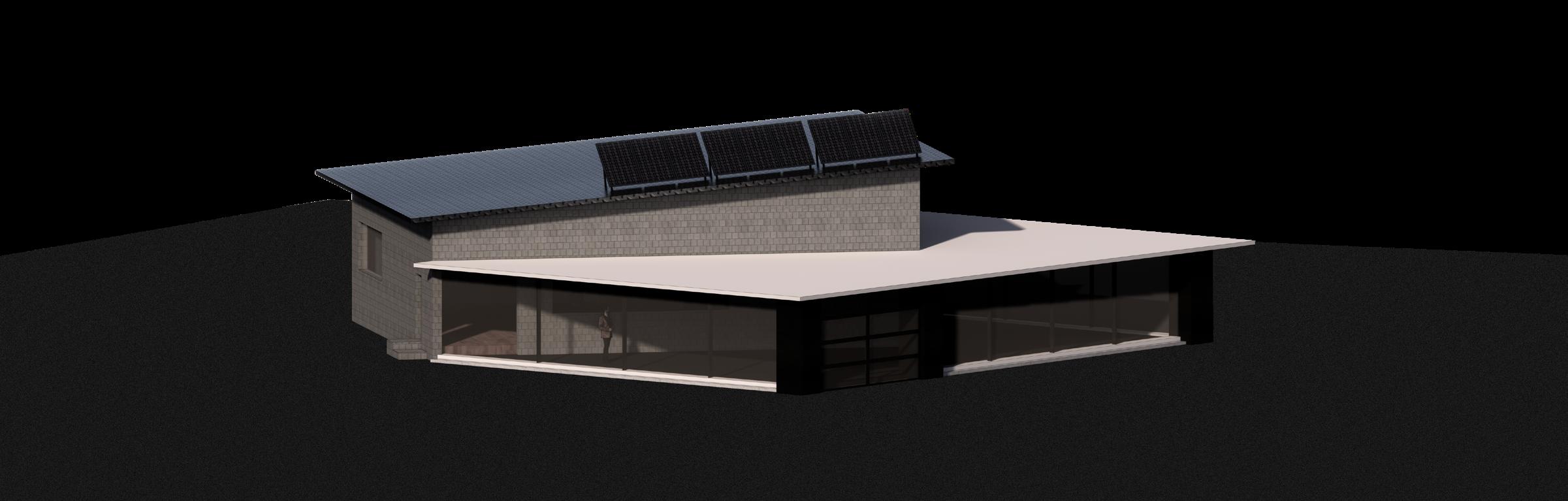
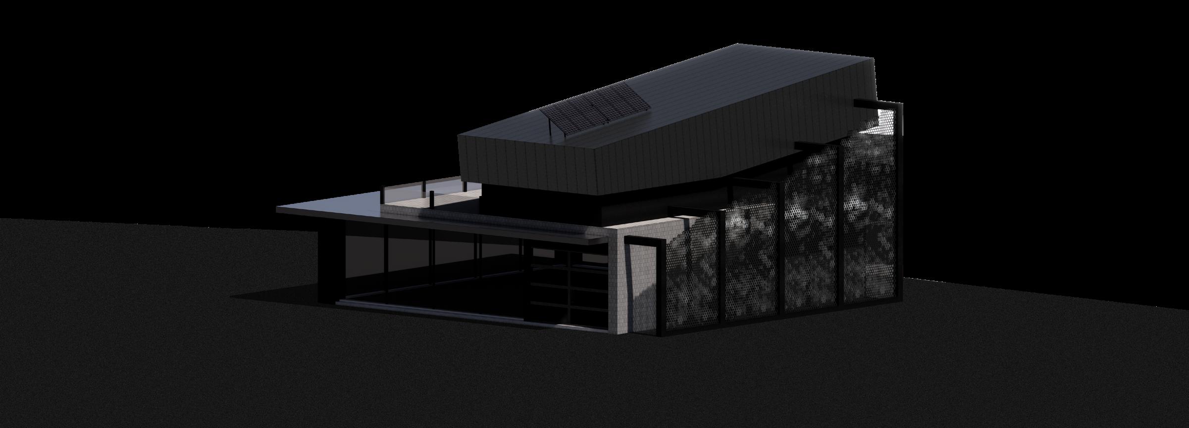
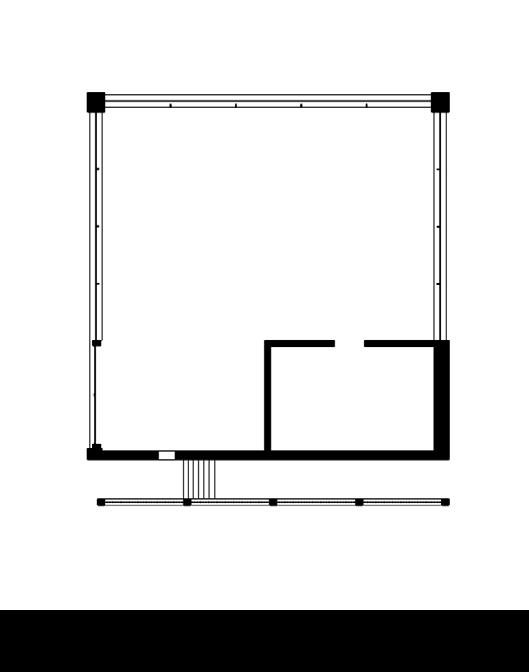
In recent years, a blur in the work and personal lives of people started to blend together. The result of that combination was a new type of architecture called Work/Live Design where a work and living area are under the same roof. In this project, we explore how 3 distinct individuals, a Brewer, Welder, and Landscape Designer coexist and share a site area.
A key concept that I wanted each building to share is the idea of architecture being a form of advertisement. Their buildings would reflect or highlight their specializations. The BREWER would have large windows allowing the brewery to be seen by passing pedestrian and traffic. The WELDER has a large metal decorative mesh incorporated as part of the staircase. The LANDSCAPE DESIGNER would have a unique way of portraying their creativity and design capabilities. Each of these buildings are comprised of their living quarters as well as space for work necessities.
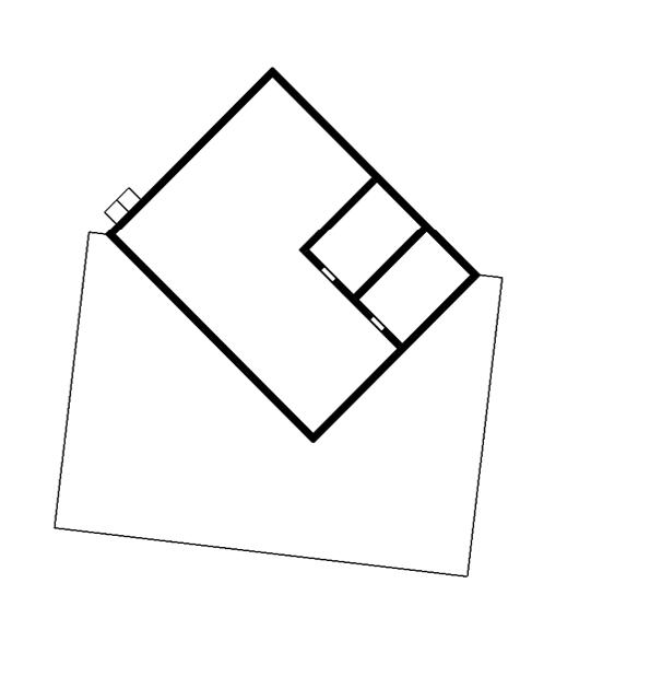
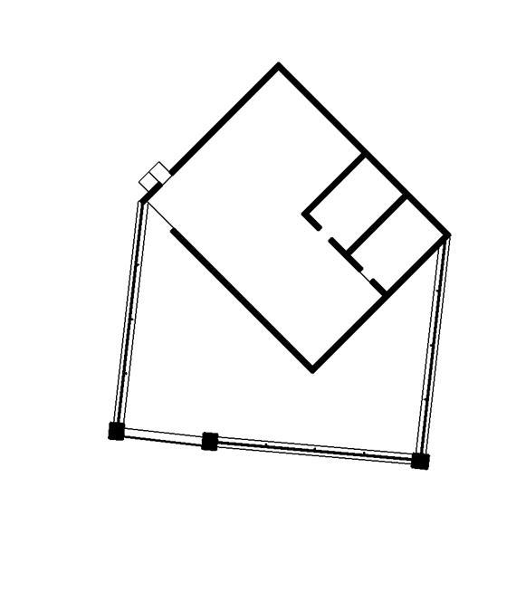
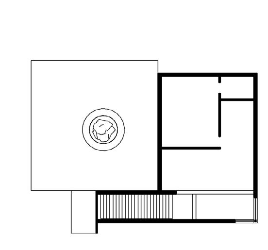
PLAN @ LEVEL 02
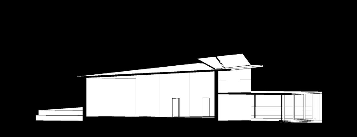
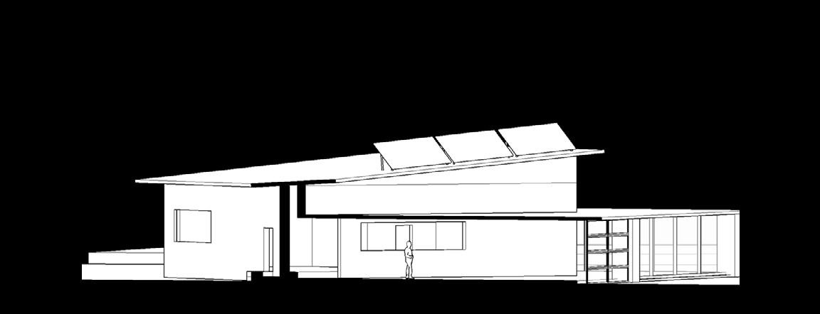
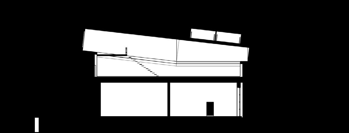
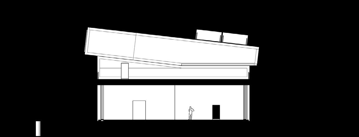
SECTION (B)
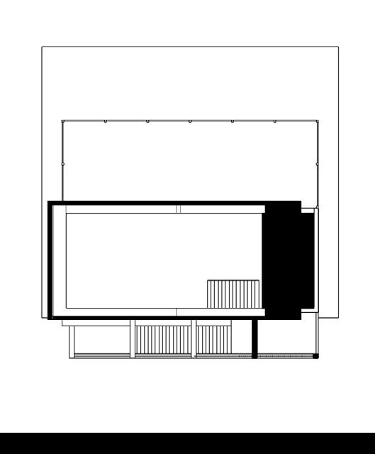
PLAN @ LEVEL 01
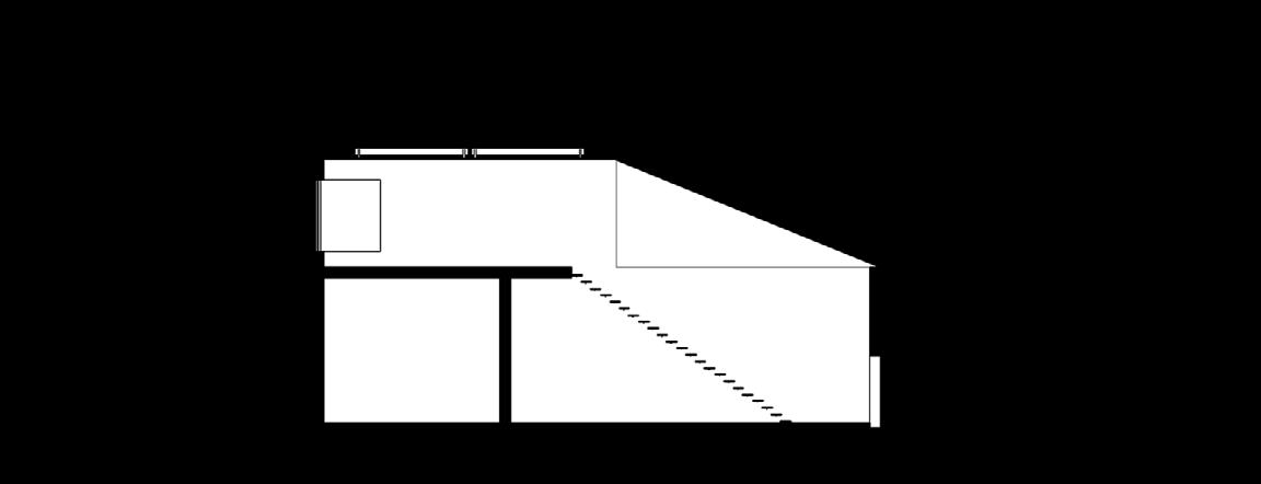
SECTION (A)
PLAN @ LEVEL 02
SECTION (B)
PLAN @ LEVEL 01
SECTION (A)


