
Interfacing with Sensors
EE 310/EE310L - Mcirocontrller - Spring 2023
NAME: Gabe Esquibel
Assignment # 8

DATE:4/19/23
https://docs google com/document/d/1xR j4MNwY KVsuxbq-4sMxH8 nPPYu1C/edit?usp=sharing&ouid=111229422470150013614&rtpof=true&sd=true
1. Assignment Overview
This assignment must be done in C programing language! In this experiment, we will be interfacing various sensors and actuators to the PIC processor.
2. Learning Objectives
By the end of this lab, you will
● Learn about IO port constraints
● Learn about the basic operation of relays
● Understand the difference between sensors and actuators
● Learn about various interfaces between different sensors and actuators
3. Review
Consider reviewing the following before you start this assignment (must be logged on SSU to open the links):
● Read about relays
● Read about photodiodes
● Read about DC Motors
Additional useful likes:
● Read the tutorial on MPLABX
● Review the assembly instruction command list.
● Programming PICF18 using PICKIT4
● Full datasheet for the 40PIN PDIP PIC18F46K42
https://ww1 microchip com/downloads/en/DeviceDoc/PIC18(L)F26-27-45-46-47-55-56-57
K42-Data-Sheet-40001919G pdf
ATTENTION: THIS ASSIGNMENT MAY TAKE YOU SOMETIMES TO COMPLETE! PLEASE START EARLY.
4. Materials
1. DC motor (1)
2. photodiodes (2)
3. relays (1)
4 switches (1)
5 2N2222 NPN transistors (1)
6 2xAA batteries with a case
7 LED (7)
8 PIC18F chip
9 Please refer to Programming PICF18 using PICKIT4.
10. Optional: two Metal Ball Tilt Shaking Position
Remember: by now you should have all these parts, per our Part List.
5. Background Information
Sensors are an integral part of modern living If you are reading this article on a computer, you are most likely using a mouse, which contains an optical sensor If you are on a smartphone, you are using touch sensors every time you touch the screen
A sensor is a device that measures physical input from its environment and converts it into data that can be interpreted by either a human or a machine Most sensors are electronic (the data is converted into electronic data), but some are more simple, such as a glass thermometer, which presents visual data People use sensors to measure temperature, gauge distance, detect smoke, regulate pressure, and a myriad of other uses
There are two types of electronic sensors: analog and digital Analog sensors convert physical data into an analog signal Analog sensors are much more precise than digital sensors, which are limited to a finite set of possible values Here are some examples of sensors:
● Light sensor
● Motion sensor
● Temperature sensor
● Magnetic fields sensor
● Gravity sensor.
● Humidity sensor.
● Moisture sensor.
● Vibration sensor.
An actuator is a device that uses a form of power to convert a control signal into mechanical motion. From electric door locks in automobiles to ailerons on aircraft, actuators are all around us See Appendix B for examples of sensors and actuators
As a reminder: GPIO stands for “General Purpose Input/Output pins“ In fact, most of the pins in a typical microcontroller are GPIO pins except for some special pins The PIC18F46K42 devices have six I/O ports Each port has ten registers to control the operation These registers are
● PORTx registers (reads the levels on the pins of the device)
● LATx registers (output latch)
● TRISx registers (data direction)
● ANSELx registers (analog select)
● WPUx registers (weak pull-up)
● INLVLx (input level control)
● SLRCONx registers (slew rate control)
● ODCONx registers (open-drain control)
6. Interfacing Actuators and Sensors to the PIC
In this assignment imagine that we would like to design a safebox with two touchless switches The user must use the touchless switches to enter the correct secret code and open the box
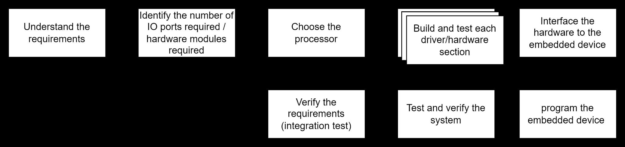
6.1 Design Process
The following figure shows the general process of designing a system involving an embedded system and firmware design In short, Firmware is software that provides basic machine instructions that allow the hardware to function and communicate with other software running on a device
6.2 Project Requirements
The purpose of this assignment is to design a system containing several actuators, sensors, and drivers The figure below shows the interfaces on the box
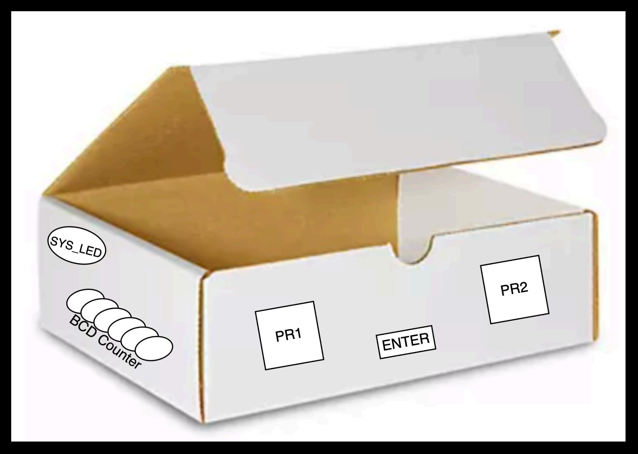
Figure 1: Safebox interfaces Note that we don’t actually build the box! We are only designing the electronics in this project
The following are the design requirements:
1 As long as power is available the system is enabled When the system is enabled, a LED must be on (this is shown as SYS LED in Figure 2)
2. The program must contain a pre-selected code called the SECRET CODE.
3 The system must operate using two touchless switches The touchless switches will be based on two photoresistors (PR1 and PR2).
4 When PR1 and PR2 result in a LOW signal the SYS LED is turned OFF for 2 seconds to tell the user the logic low was registered (This feedback mechanism is optional, but somehow you need to know if the system registered the activity)
5 When the system is enabled, the user should be able to enter a SECRET CODE using the touchless switches:
a As an example, one scenario could be the following: if the secret code is 0x23, then the user must first cover (create darkness on) the PR1 three times and then cover PR2 two times Once the secret code is entered, the ENTER BUTTON must be pressed
6 If the entered SECRET CODE is correct, then the buzzer or the motor should be turned on
7 If the entered SECRET CODE is incorrect, then SYS LED must blink at the rate of about 1 blink/0 5seconds for 2-4 seconds and then stop
a No new values can be entered while the SYS LED is blinking
8. The user can re-attempt a new code as soon as the previous code is processed.
9 When the system is enabled, the software must show a count (the count could represent the number of times a valid secret code has been entered). The BCD count can represent any other parameter of your choice
10. The count value must be in packed BCD using 6 LEDs, representing 0-39 decimals.
Read Chapter 7 for more information about BCD representation. In this project, we can use an active buzzer Refer to Appendix B to see an ACTIVE buzzer You can also use a relay module, as shown in Appendix B.
Also note that the SECRET CODE can be changed during the demonstration, upon the request of the instructor
6.3 Hardware Design
The figure below shows the general circuitry for this project Note the following in the figure:
1 The relay must be connected to the PIC using a transistor driver as shown in the figure
2 The photodiode must be such that it generates a digital signal (high/low) depending on the intensity of the light You can always use your phone to increase the light intensity of the light sensor
3 The transistor and the resistors on the driver circuit can be anything as long as the circuit operates properly
4 The relay can be used to energize a DC motor or a buzzer
5 Although not shown in the figure, we need to have a separate power source to energize the DC motor or the buzzer connected to the relay.
It is important to keep the power to the motor separate from the power to the microcontroller and the photoresistor That is V external must be separated from Vss Similarly, the grounds must be separated from one another between the motor and the microcontroller, and the photoresistor, as shown in the figure below
An important aspect of our design is to fully understand the GPIO port requirements As shown in the table below, the minimum required voltage for logic high is 3.0V. The minimum required voltage for logic low is 1 6V or smaller voltages Note that the input voltage should never exceed 5V.
The figure below shows the logic levels during the transition of the input. At 3.0V the processor registers the input as a high signal Anything less than 1 8V is registered as logic low

6.4 Identifying the IO Ports
Referring to Figure 1, let’s identify which ports can be used for different modules This is an important step in choosing the right embedded device. Complete the pinout table, below
Function Input/Output?
Photo Input 1 Input
RC3
Photo Input 2 Input RC2
EnterKey Input RC1
Reset Input RA3
SetCombo Input RC0
Indicator 1 LED Output RC6
Indicator 2 LED Output RC7
Red LED Output RA5
Relay Output RA4
BCD LEDs Count (Lower Nibble) Output RD0 -> RD3
BCD LED Count (Upper Nibble) Output RB0 -> RB1
6.5 Test the photoresistor circuit
Do the following one step at a time. Make sure your circuit is correctly working before interfacing it with the PIC processor
1 Characterize your photoresistor as explained here Identify if your sensor’s resistance increases or decreases as the light increases. Complete the table below:
Light Intensity
Very high-intensity light
Medium-intensity light
Very low-intensity light
/ PR2
/ PR2
/ PR2
1k / 0k
/ 7k
/ 100k
2 Build the photoresistor circuitry Make sure when there is no light present your circuit generates at least 4V and when there is light it generates less than 2 Volts (or vice versa). These are the required voltage to activate the IO ports of the PIC. Choose the appropriate resistor values Use a Vin=5V power supply to energize your circuit Your circuit would be something light the figure shown here.

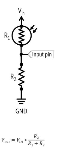
Figure 2(a): Analyzing the photoresistor circuit
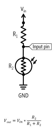
Figure 2(b): Two possible circuits to interface with a photoresistor. The Outlined circuit in red is the one that was ultimately implemented into the final circuit
Light Intensity
Very high-intensity light PR1 / PR2
at Input Pin (as shown in figure 3b)
40 V / 0 46 V
Medium-intensity light PR1 / PR2 1 71 V / 2 14 V
Very low-intensity light PR1 / PR2 4 16 V / 3 54 V
3 Apply your circuit and make sure you can turn on an LED depending on how you designed your circuit. Note that you may want to add a resistor before the LED. Make sure you can turn on the LED, depending on the light intensity
4 Remove the LED Calculate all the voltages and complete the table below:
Light Intensity V R (measure) I Total (calculate) V PR* Very high-intensity light PR1 / PR2
V / 0 15 V Medium-intensity light PR1 / PR2
/ PR2
* Voltage on the photoresistor
6.6 Example of photoresistor calculation
Assume a test case shows R photoresistance at room temperature is 2 8 KOhm Assume the input voltage is 5V and we want the output voltage to the microcontroller to be 3.7V. Thus, we will have: 5����1
= 3.7
Thus, having R2=8K ohm would generate a HIGH logic, when the photoresistor is at the room temperature
Now assume, in our case, the R photoresistance at complete darkness is 23 KOhm Let’s use our 8Kohm value and see what voltage we can generate in total darkness We use the same relationship:
5��×8�� 8��+23 = �������� = 1.3��
The Vout is well below 1 8V as mentioned above and thus 8Kohm seems to be a good choice
6.7 Test the relay circuit
First let’s examine your relay. Referring to the relay datasheet, answer the following questions:
Relay Model: 5V DC JOC-3FF-S-Z Is the relay normally CLOSED or OPEN? Relay is Normally Open
Relay Coil Current:71.4mA
Relay Coil Resistance: 69 +/- 10% Ω
Relay Voltage Contact Rating): 3 75V
Relay Current Contact Rating): 10A
The relay module is equipped with an internal driver circuit for convenience
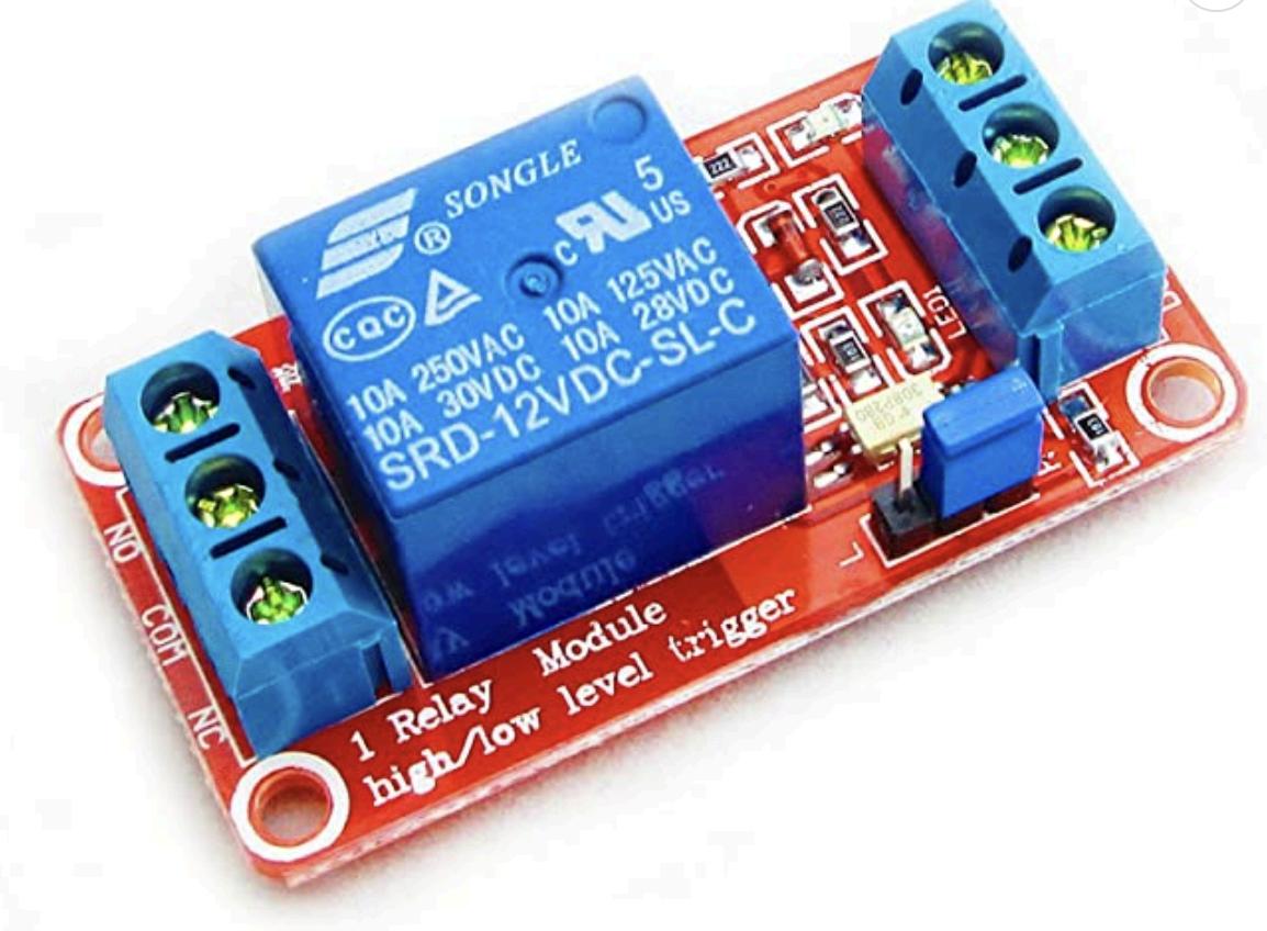
Figure3(a):SimilarModulewasused usingaJQC-SFF-S-Z
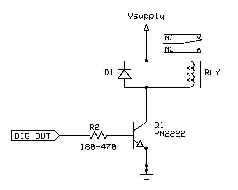
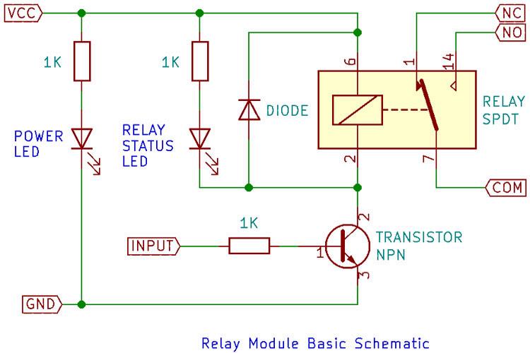
Figure3(b):Schematicoftherelaymodule.
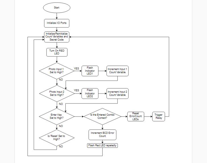
6.8 Flowchart
Show your software flowchart. You can use draw.net, VISIO, or any other professional software for drawing flowcharts
6.9: Comment Block

Figure 5: Comment block of code that precedes the main program. Description of ports and compiler as well as the purpose of the script.
6.10 Firmware Design Using C Code
Make sure your code has comments Your code and your software flowchart MUST match! So, make sure your flowchart properly represents what you have coded.
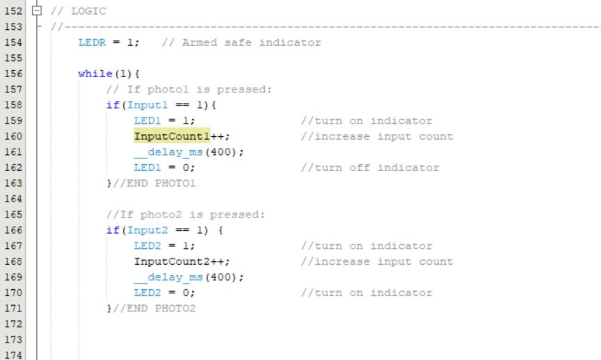
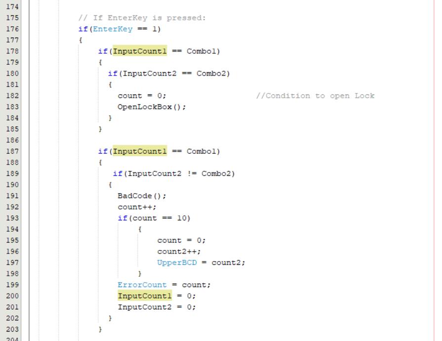
Figure 6: Code behind the lock box mechanism First 50 lines only
6.11 High-Level Block Diagram
Complete your high-level block diagram, similar to Figure 2 In your figure show the general connections to various components You do not need to include the details The purpose of the high-level diagram is to depict a high-level understanding of the system; for example, a driver is a box and there is no need to show all the details of the driver We show the high-level block diagram to our customers to make sure we meet all their general requirements
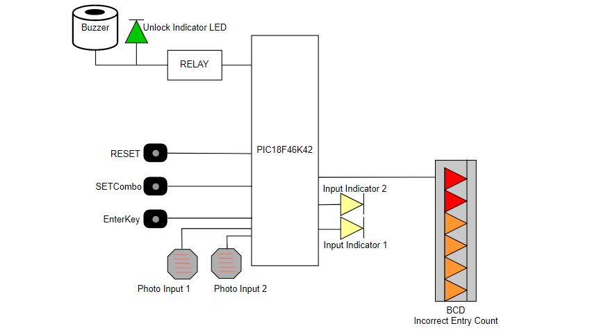
Figure 7: High Level block diagram of PIC18F46K42 with its peripherals.
6.12 Circuit Diagram
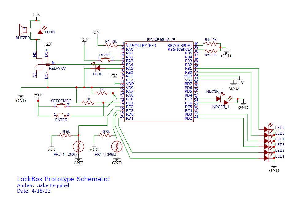
Figure 8: EasyEDA circuit circuit diagram of PIC18F46K42 lock box circuit with all hardware connections.
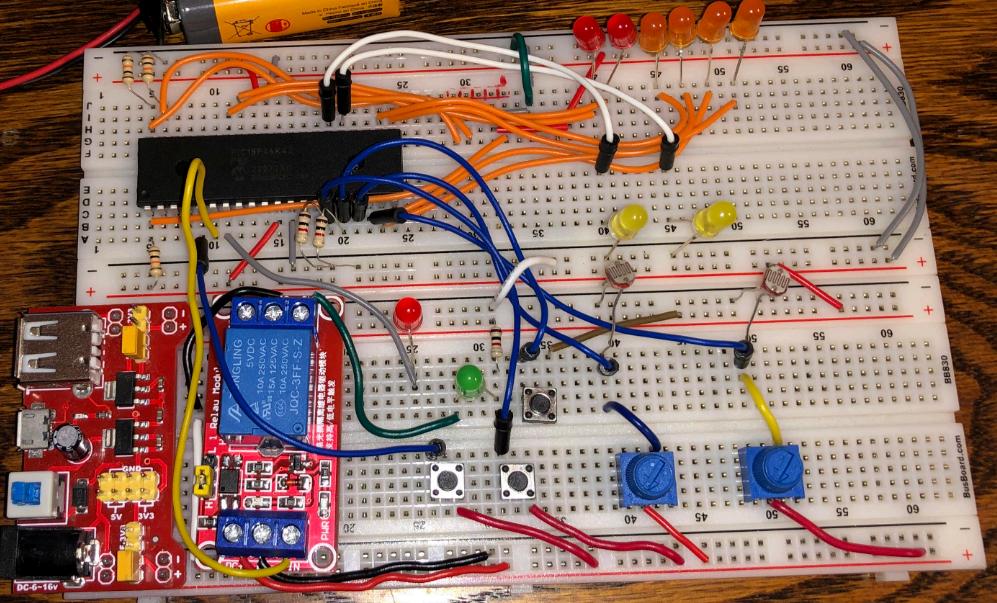
6.13 Circuit Image:
6.14 Answer the Following Questions
1- Clearly state all your requirements for this project and highlight the ones that you added on your own Number them, clearly please!
The requirements for this project are as follows:
- The two inputs to enter the combination must be photoresistor sensors.
- The six output LEDs (1 through 6) must incorporate the concept of binary coded decimal in some way. In this case they count the number of incorrect entries.
- The output that will simulate the opening of the lock box but be triggered by a 5V relay In this case, to simulate the opening operation, a green LED and a buzzer will go off after the PIC18 triggers the relay
- When an incorrect passcode is entered, notify the user through a red flashing LED
- Another input to confirm the passcode, an Enter button must be pressed to check the password
Additional Features:
- There will be two more inputs implemented The first button ‘Set Combo’ will repurpose the operation of the photo inputs to instead set a custom user preferred passcode which allows customization without reprogramming only when the ‘Set combo’ button is held
- The second input will reset the combo to 0 and 0 only when the SetCombo button is held
- Two input indicators will be added to display to the user that their input was registered
7. Survey Questions
Answer the following questions, please:
Survey question
On a scale of 1-10 how did you like this exercise? (10 is the best, 1 is the worst)
On a scale of 1-10 how much did you learn as a result of completing this exercise? (10 = plenty; 1=very little)
How many hours did you spend completing this exercise?
8. References
Response
10
9
Around 12 or more
[1] Complete Electronics Self-Teaching Guide with Projects | Earl Boysen, Harry Kybett
ISBN: 978-1-118-28232-8 July 2012
[2] Datasheet: https://ww1 microchip com/downloads/en/DeviceDoc/PIC18(L)F26-27-45-46-47-55-56-5 7K42-Data-Sheet-40001919G pdf
[3] PIC18F Instruction Sets: https://onlinelibrarywileycom/doi/pdf/10 1002/9781119448457 app4
[4] List of Instructions: http://143 110 227 210/faridfarahmand/sonoma/courses/es310/resources/201402171244 22790 pdf
