1 GENERAL CONSIDERATIONS
1.1 CONDITIONS OF USE
1.1.1 Design considerations
See Section 2.2
1.1.2 Application
The assessment of the System relates to its use in accordance with this Agrément and the Agrément holder’s requirements.
1.1.3 Assessment
Kiwa Ltd. has assessed the System in combination with relevant test reports, technical literature, the Agrément holder’s quality plan, DoPs and site visit, as appropriate
1.1.4 Installation supervision
The quality of installation and workmanship must be controlled by a competent person who must be an employee of an Approved Installer.
The System shall be installed strictly in accordance with the instructions of the Agrément holder and the requirements of this Agrément.
1.1.5 Geographical scope
The validity of this document is limited to England, Wales, Scotland, Northern Ireland and Ireland, with due regard to Chapter 3 of this Agrément (CDM, national Building Regulations and Third-Party Acceptance).
1.1.6 Validity
The purpose of this BDA Agrément® is to provide for well-founded confidence to apply the System within the scope described. The validity of this Agrément is three years after the issue date, and as published on www.kiwa.co.uk/bda.
1.2
PRODUCTION CONTROL AND QUALITY MANAGEMENT SYSTEM
Kiwa Ltd. has determined that the Agrément holder fulfils all their obligations in relation to this Agrément, in respect of the System
The initial audit demonstrated that the Agrément holder has a satisfactory Quality Management System (QMS) and is committed to continuously improving its quality plan. Document control and record-keeping procedures were deemed satisfactory. A detailed Production Quality Specification (PQS) has been compiled to ensure traceability and compliance under the terms of this Agrément.
1.3 ANNUAL VERIFICATION PROCEDURE - CONTINUOUS SURVEILLANCE
To demonstrate that the System conforms with the requirements of the technical specification described in this Agrément, an Annual Verification Procedure has been agreed with the Agrément holder in respect of continuous surveillance and assessment, and auditing of the Agrément holder’s QMS.
2 TECHNICAL ASSESSMENT
This Agrément does not constitute a design guide for the System. It is intended as an assessment of safety and fitness for purpose only.
2.1 ANCILLARY ITEMS
The following ancillary items detailed in this Section may be used in conjunction with the System but fall outside the scope of this Agrément:
• superbead® delivery and injection system - specially designed injection gun for horizontal void fill (hereinafter ‘injection gun’) , connected to an airline and hoses to deliver the System at known flow rates into the underfloor void;
• drill - used to drill holes at butt joints of beam-and-block floors (or in blocks if not possible) to enable filling of the underfloor void;
• borescope - used to determine the location and orientation of services, pipes and cables within the void, and to confirm that a DPM has been correctly installed prior to the installation of the System;
• barrier brushes - used to plug drill holes close to any hole being filled, to prevent the System escaping from those holes;
• DPM - 1200 gauge membrane, installed with appropriately jointed laps and continuous with the damp- proof course (hereinafter ‘DPC’);
• vapour control layer (hereinafter ‘VCL’) - a suitable membrane with high water-vapour resistance relative to the DPM, installed on the warm side of the System;
• floor screed - in accordance with BS EN 13813 applied onto the VCL above beam-and-block floors, to provide a base for the internal flooring.
2.2 POINTS OF ATTENTION TO THE SPECIFIER
2.2.1 Design responsibility
A specifier may undertake a project-specific design, in which case it is recommended that the Specifier co-operates closely with the Agrément holder. The Specifier or installing contractor is responsible for the final as-built design.
The Approved Installer is responsible for the design of the project-specific drilling pattern and System installation plan.
2.2.2 Applied building physics (heat, air, moisture)
A competent specialist shall check the hygrothermal behaviour of a project-specific design incorporating the System, and if necessary, offer advice in respect of improvements to achieve the final specification. The Specialist can be either a qualified employee of the Agrément holder or a suitably qualified consultant (in which case it is recommended that the Consultant S pecialist co-operates closely with the Agrément holder).
2.2.3 General design considerations
The System:
• is only for use on sites which do not require additional ground protection from flooding;
• consideration of ground gases, which is outside the scope of the Agrément, shall be carried out in accordance with BS 8485;
• can be used to install underfloor void insulation of thicknesses between 100 mm to 250 mm;
• can be installed in beam-and-block floors with any block size and orientation which can be accommodated within the maximum drill pattern spacing of 900 mm centres
Additional work shall be carried out as follows:
• a suitable DPM with adequate laps, taped joints and continuation with the DPC shall be installed prior to installation of the System;
• it is recommended that a VCL is installed after installation of the System to help minimise interstitial and surface condensation, in accordance with BS 5250;
• following installation of the System, the entire floor shall be covered with a floor screed.
2.2.4 Project-specific design considerations
The project-specific design shall take into account the service life durability required - see Section 2.2.12
The project-specific design shall take into account the requirements of the national Building Regulations - see Section 3.2
A pre-installation survey is required to allow determination of the project-specific design - see Section 2.4.
The perimeter/area ratio of any building designed to incorporate the System shall be taken into consideration when calculating the underfloor void depth requirement of beam-and-block floors, in accordance with BS EN ISO 10211 and BS EN ISO 13370, to achieve a required insulation thickness and target Uvalue.
2.2.5 Permitted applications
Only applications designed according to the specifications given in this Agrément are permitted. In each case, the Specifier and Installer shall co- operate closely with the Agrément holder.
The System is for use in watertight, roof-covered dwellings
2.2.6 Installer competence level
The System shall be installed strictly in accordance with the instructions of the Agrément holder and the requirements of this Agrément.
Installation shall be by an Approved Installer, trained and approved by the Agrément holder.
2.2.7 Delivery, storage and site handling
The System components are delivered in suitable packaging bearing the System name, the Agrément holder’s name and the BDA Agrément® logo incorporating the number of this Agrément.
Prior to installation, the System components shall be stored in accordance with the Agrément holder’s requirements. The System components are not susceptible to damage from environmental conditions normally encountered in the UK and Ireland. However, good housekeeping pr otocols shall be followed to avoid damage.
Where required, particular care shall be taken to:
• avoid exposure to direct sunlight for extended periods of time;
• avoid exposure to high or low temperatures for extended periods of time;
• store in a well-ventilated covered area to protect from rain, frost and humidity;
• store away from sources of ignition
2.2.8 Maintenance and repair
Once installed, the System does not require maintenance
Services within beam-and-block floors may require maintenance. Minor adjustments to services are unlikely to cause any disruption to the installed System. An Installer can refill any voids created where it has been necessary to remove the System for maintenance of services.
If the maintenance of services requires disruption to the DPM, VCL, floor screed or beam-and-block floors, guidance shall be sought from the manufacturers of those products to ensure the floor continues to achieve the necessary performance levels. For further advice in respect of repair, consult the Agrément holder.
Performance factors in relation to the Major Points of Assessment
2.2.9 Adequacy of fill
Beam-and-block floors with an underfloor void depth of between 100 mm to 250 mm can be fully filled with the System (with no gaps and a consistent density) The adhesive ensures that the System remains stable within the underfloor void and has adequate resistance to settlement.
2.2.10 Moisture control
Beam-and-block floors incorporating the System will adequately limit the risk of surface and interstitial condensation, when designed in acc ordance with BS 5250 and BS EN ISO 13788.
The System is used in conjunction with a pre-installed DPM to prevent the ingress of ground moisture into the interior of the underfloor void space.
The System does not absorb water by capillary action. Tests confirm the System will not transmit moisture by capillary action into the interior of the building through the floor.
2.2.11 Thermal performance
For the purpose of U-value calculations and to determine if the requirements of national Building Regulations are met, the thermal resistance and U- value of beam-and-block floors incorporating the System shall be calculated in accordance with BS EN ISO 10211 (taking into consideration BS EN ISO 6946, BS EN ISO 10456, BS EN ISO 13370 as a ‘slab-on-ground floor’ and BRE Report 443), using the System’s declared thermal conductivity (λD) value.
2.2.12 Durability
The System shall have a service life durability equivalent to that of the building into which it is incorporated. The expected lifespan of the building itself should be at least 60 years.
2.2.13 UKCA and CE marking
The British standard for the System is BS EN 16809-2
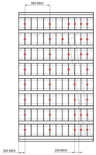
Diagram 1 - Typical drill pattern
2.3 EXAMPLES OF TYPICAL DETAILS
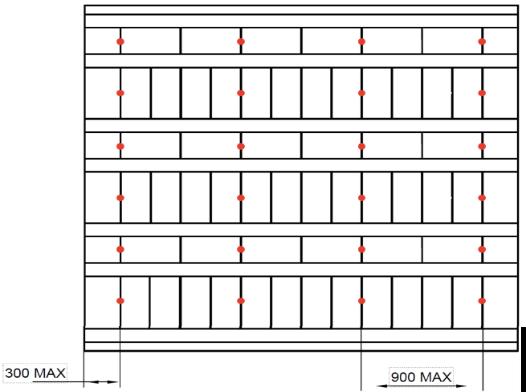
Diagram 2 - Alternate floor design and drill pattern
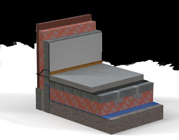
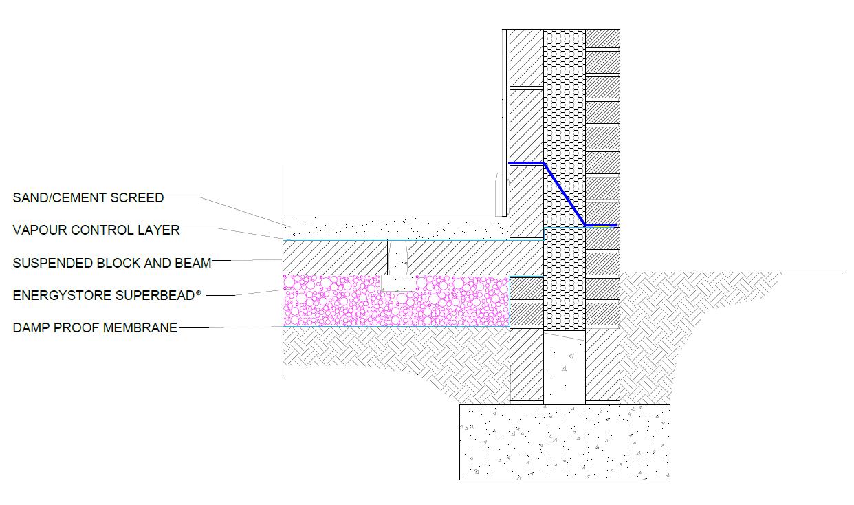
Diagram 3 - Schematic diagram of recommended flooring specification
2.4 INSTALLATION
The System shall be installed strictly in accordance with the instructions (hereinafter ‘Installation Manual’) of the Agrément holder , the requirements of this Agrément and the requirements of BS 8000-0
2.4.1 Installer competence level
See Section 2.2.6.
2.4.2 Delivery, storage and site handling
See Section 2.2.7
2.4.3 Project-specific installation considerations
The project-specific design shall be determined from a pre-installation survey.
The primary requirement of the pre-installation survey is to determine the following:
• that the building has a watertight roof covering;
• that beam-and-block floors have been installed as specified and are dry; installation shall not be carried out where there is evidence of pooled water or damp;
• to assess project-specific hazards and risks to help prevent damage to the building, and to alert Installers to any potential health and safety issues;
• the average void depth, using a minimum of two borescope inspections per room (eight per building); the void depth shall be between 100 mm to 250 mm Any significant deviation in the requested design depth from that of the borescope-measured depth shall be brought to the attention of the site agent/designer, as this could affect the U-value and condensation risk assessment;
• that a DPM (1200 gauge) polyethylene sheet has been installed in accordance with the manufacturer’s instructions, particularly with respect to adequate joining of the laps, continuation of the DPC, and with airtight seals around services. If the membrane is damaged or incomplete, repairs shall be carried out as per the technical requirements of the membrane manufacturer;
• the location and orientation of any services running within the underfloor void, to guide the design of the drilling pattern;
• any drains, waste pipes and cable runs are undamaged before installation of the System. Any damage shall be reported to the site agent.
2.4.4 Preparation
The following considerations apply before starting the work:
• when laying delivery hoses from the delivery vehicle to the building, step- over ramps and hazard signs may be necessary to safeguard pedestrians, customers and Installers;
• any pipes or cables protruding through the floor shall be checked to ensure they have been appropriately sealed;
• Installers shall have appropriate PPE for each stage of the installation.
The following works shall be undertaken before the installation of the System:
• installation equipment shall be inspected daily prior to commencement of work, with the results of these inspections recorded;
• the operating pressures for the delivery of EPS beads and adhesive shall be set in accordance with the Agrément holder’s instructions;
• flow rates shall be determined as follows:
o the flow rate (kg/min) of EPS beads shall be determined by measuring the total weight of EPS beads delivered into a hessian bag over a 30 or 60 second interval;
o the adhesive flow rate shall be measured by first selecting the appropriate nozzle aperture based on the measured flow rate of the EPS beads (refer to the Installation Manual for details); the adhesive (in mist form) is then sprayed into a measuring cylinder and the volume recorded (once any foam has subsided) over a 30 or 60 second interval. Adjust the pressure on the injection gun to achieve the target adhesive flow rate.
• the correct nozzle length and depth stop on the injection gun shall be selected according to the block thickness.
2.4.5 Outline installation procedure
The detailed installation sequence can be found in full in the Agrément holder’s Installation Manual.
Drill pattern
• the drill pattern is determined following the initial borescope survey and depends upon the size and orientation of concrete blocks used, in conjunction with the beams, and the extent and orientation of void services and protrusions;
• a drilling pattern for typical beam-and-block floors inclusive of a service pipe is represented in Diagram 1, with an alternate floor design and drilling pattern represented in Diagram 2 (see Section 2.3). Other configurations not represented in this Agrément can be accommodated by the System, as long as the key principles outlined below are followed:
o each row of blocks within the floor layout shall have drill holes;
o the drill pattern shall have as many of the drill holes as possible at the joints between blocks;
o the first drill holes in each row shall be a maximum of 300 mm from the wall;
o drill holes in each row of blocks shall be at maximum 900 mm centres;
o additional drill holes shall be drilled around any services or obstructions, at a maximum distance of 200 mm apart.
Drilling operations
• drilling shall be carried out in accordance with the agreed drill pattern;
• whenever possible, drilling shall be carried out through the butt joints of the floor blocks at maximum 900 mm centres. However, where this is not possible or where drill hole spacings would exceed 900 mm centres, holes may be drilled through the blocks. Holes shall not be drilled though beams;
• holes are to be drilled vertically with application of light pressure only (to minimise debris falling into the under-floor void);
• 22 to 26 mm diameter drill bits shall be used (the length of the drill bits shall exceed the thickness of the block by no more than 10 mm);
• injection of the System into the void shall not commence until all holes have been drilled.
Injection
The key sequence for installation is:
• injection shall begin at drill holes around obstructions, before following the approved drill pattern starting at a hole located where two corners of external walls meet;
• drill holes adjacent to those being injected shall be filled with barrier brushes to prevent the System from escaping during the injection process;
• the nozzle of the injection gun shall be inserted halfway into the drill hole and the gun control valves opened to deliver the System into the underfloor void;
• the void shall be filled completely until back pressure stops the flow of the System (which can be seen through the clear hose feeding the EPS beads to the injection gun);
• once the flow of the System has stopped, the adhesive valve shall be closed immediately;
• the injection process shall be repeated for each drill hole until the entire floor is completed.
2.4.6 Finishing
The following finishing is required on completion of the installation:
• drains, waste pipes and cable runs shall be checked for damage. Any remedial action required shall be reported at the earlies t opportunity;
• drill holes shall be filled with a cylindrical plug of mortar; the surface shall be levelled off with a trowel flush with the floor;
• the floor shall be swept clean;
• the works shall be checked by the Installer and customer before being signed off as completed.
2.5 INDEPENDENTLY ASSESSED SYSTEM CHARACTERISTICS
2.5.1 Adequacy of fill (using specified installation machinery and drilling pattern)
The filling of underfloor voids with the System has been witnessed in situ, including:
• bespoke System pre-install checks;
• the correct drilling pattern and accuracy;
• the correct injection technique;
• completeness of void fill during and post installation;
• depth of void fill under beam-and-block floors
2.5.2 Moisture control
Test Standard Result
Water vapour resistance factor µ
BS EN 12524 2
Short-term water absorption (24 hour) by partial immersion at 23 °C, 50 % RH BS EN 1609 Method A < 1.0 kg/m2
2.5.3 Fire performance
Test Standard Result Reaction to fire classification BS EN 13501-1 E
2.5.4 Thermal performance
Test Standard Result
Declared aged thermal conductivity (λD)
2.5.5 Other
BS EN 12667 0.033 W/mK
Test Standard Result
EPS bead size diameter by passing samples through a graded series of sieves
Installed target mean apparent density over the entire installation
BS EN 933-1 2 to 8 mm
BS EN 1602 12 ± 2 kg/m3
3.1 THE CONSTRUCTION (DESIGN AND MANAGEMENT) REGULATIONS 2015 AND THE CONSTRUCTION (DESIGN AND MANAGEMENT) REGULATIONS (NORTHERN IRELAND) 2016
Information in this Agrément may assist the client, principal designer/CDM co-ordinator, designer and contractors to address their obligations under these Regulations.
3.2 THE NATIONAL BUILDING REGULATIONS
In the opinion of Kiwa Ltd., the System, if installed and used in accordance with Chapter 2 of this Agrément, can satisfy or contribute to satisfying the relevant requirements of the following national Building Regulations.
This Agrément shall not be construed to confer the compliance of any project-specific design with the national Building Regulations.
3.2.1 England
The Building Regulations 2010 and Subsequent Amendments
• C2(a) Resistance to ground moisture - the System does not absorb water by capillary action
• C2(c) Resistance to interstitial and surface condensation - the System can contribute to satisfying this Requirement
• L1(a)(i) Conservation of fuel and power - the System can contribute to limiting heat gains and losses through a floor
• Regulation 7(1) Materials and workmanship - the System is manufactured from suitably safe and durable materials for its application and can be installed to give a satisfactory performance
• Regulation 26 CO2 emission rates for new buildings - the System can contribute to a building not exceeding its CO2 emission rate
• Regulation 26A Fabric energy efficiency rates for new dwellings - the System can contribute to satisfying this Requirement
3.2.2 Wales
The Building Regulations 2010 and Subsequent Amendments
• C2(a) Resistance to ground moisture - the System does not absorb water by capillary action
• C2(c) Resistance to interstitial and surface condensation - the System can contribute to satisfying this Requirement
• L1(a)(i) Conservation of fuel and power - the System can contribute to limiting heat gains and losses through a floor
• Regulation 7(1) Materials and workmanship - the System is manufactured from suitably safe and durable materials for its application and can be installed to give a satisfactory performance
• Regulation 26 CO2 emission rates for new buildings - the System can contribute to a building not exceeding its CO2 emission rate
• Regulation 26A Primary energy consumption rates for new buildings - the System can contribute to satisfying this Requirement
• Regulation 26B Fabric performance values for new dwellings - the System can contribute to satisfying this Requirement
3.2.3 Scotland
The Building (Scotland) Regulations 2004 and Subsequent Amendments
3.2.3.1 Regulation 8(1) Durability, workmanship and fitness of materials
• The System is manufactured from acceptable materials and is adequately resistant to deterioration and wear under normal servi ce conditions, provided it is installed in accordance with the requirements of this Agrément
3.2.3.2 Regulation 9 Building standards - construction
• 3.4 Moisture from the ground - the System does not absorb water by capillary action and can contribute to a construction satisfying this standard with reference to clause 3.4.1 of the Technical Handbooks
• 3.15 Condensation - a floor incorporating the System can protect a building from moisture caused by surface or interstitial condensation
• 6.2 Building ins ulation envelope - the System will contribute to the insulation envelope to resist thermal transfer
• 7.1(a) Statement of sustainability - the System can contribute to satis fying the relevant Requirements of Regulation 9, Sections 1 to 6, and therefore will contribute to a construction meeting a bronze level of sustainability, as defined in this Standard; in addition, the System can contribute to a construction meeting a high er level of sustainability, as defined in this Standard
3.2.3.3 Regulation 12 Building standards - conversions
• All comments given under Regulation 9 also apply to this Regulation, with reference to Schedule 6 of The Building (Scotland) Regulations 2004 and subsequent amendments, and clause 0.12 of the Technical Handbook (Domestic)
3.2.4 Northern Ireland
The Building Regulations (Northern Ireland) 2012 and Subsequent Amendments
• 23(1)(a)(b) Fitness of materials and workmanship - the System is suitable and can be adequately mixed, prepared and applied
• 28(a) Resistance to ground moisture - the System can contribute to satisfying this Regulation
• 29 Condensation - a floor incorporating the System can adequately protect a building from moisture in the form of interstitial condensation
• 39(a)(i) Cons ervation measures - the System will limit heat gains and losses through a floor
• 40(2) Target carbon dioxide emission rate - the System will contribute to a building not exceeding its CO2 emission rate
3.2.5 Ireland
Building Regulations 1997 and Subsequent Amendments
In order to demonstrate compliance with Irish Building Regulations, this BDA Agrément® certifies that the System complies with the requirements of a recognised document and indicates it is suitable for its intended purpose and use.
• C4 Resistance to weather and ground moisture - the System can enable a building to prevent the passage of moisture to the inside of the building
• D1 Materials and workmanship - the System is manufactured from suitably safe and durable materials for the application and can be installed to give a satisfactory performance
• L1 Conservation of fuel and energy - the System can enable a building to conserve energy and limit CO2 emissions
3.3 THIRD-PARTY ACCEPTANCE
In the opinion of Kiwa Ltd. if installed, used, and maintained in accordance with this Agrément, this System can satisfy the appropriate structural, fire, moisture, thermal, acoustic and durability requirements of a Structural Warranty provider. Please contact the relevant Structural Warranty provider to ascertain their project specific design requirements and to confirm their acceptance on a case- by-case basis.
4 SOURCES
• BS EN ISO 6946:2017 Building components and building elements. Thermal resistance and thermal transmittance. Calculation meth ods
• BS EN ISO 10211:2017 Thermal bridges in building construction. Heat flows and surface temperatures. Detailed calculations
• BS EN ISO 10456:2007 Building materials and products. Hygrothermal properties. Tabulated design values and procedures for determining declared and design thermal values
• BS EN ISO 13370:2017 Thermal performance of buildings. Heat transfer via the ground. Calculation methods
• BS EN ISO 13788:2012 Hygrothermal performance of building components and building elements. Internal surface temperature to avoid critical surface humidity and interstitial condensation. Calculation methods
• BS EN 933-1:2012 Tests for geometrical properties of aggregates. Determination of particle size distribution. Sieving method
• BS EN 1602:2013 Thermal insulating products for building applications. Determination of the apparent density
• BS EN 1609:2013 Thermal insulating products for building applications. Determination of short term water absorption by partial immersion
• BS EN 12524:2000 Building materials and products. Hygrothermal properties. Tabulated design values
• BS EN 12667:2001 Thermal performance of building materials and products. Determination of thermal resistance by means of guar ded hot plate and heat flow meter methods. Products of high and medium thermal resistance
• BS EN 13501-1:2018 Fire classification of construction products and building elements. Classification using data from reaction to fire tests
• BS EN 13813:2002 Screed material and floor screeds. Screed material. Properties and requirements
• BS EN 16809-1:2019 Thermal insulation products of buildings. In- situ formed products from loose-fill expanded polystyrene (EPS) beads and bonded expanded polystyrene beads. Specification for the bonded and loose- fill products before installation
• BS EN 16809-2:2017 Thermal insulation products of buildings. In- situ formed products from loose-fill expanded polystyrene (EPS) beads and bonded expanded polystyrene beads. Specification for the bonded and loose- fill products after installation
• BS 5250:2011+A1:2016 Code of practice for control of condensation in buildings
• BS 8000-0:2014 Workmanship on construction sites. Introduction and general principles
• BS 8485:2015+A1:2019 Code of practice for the design of protective measures for methane and carbon dioxide ground gases for new buildings
• BRE Report 443:2006 Conventions for U-value calculations
• Patent application number GB2105642.9:2021 Method and apparatus for injecting particulate insulant materials into an underfloor void
Remark - Apart from these sources, technical information and confidential reports have been assessed; any relevant documents are in the possession of Kiwa Ltd. and are kept in the Technical Assessment File of this Agrément. The Installation Manual for the System may be subject to change, and the Agrément holder should be contacted for the clarification of revisions.
5 AMENDMENT HISTORY
6 CONDITIONS OF USE
This Agrément may only be reproduced and distributed in its entirety.
Where a National Annex exists in respect of a BS EN (or other) standard, its use is deemed mandatory wherever the original standard is referenced.
Kiwa Ltd. has used due skill, care and attention in the preparation of this BDA Agrément®
Whilst all due diligence has been used, no liability or warranty is extended by Kiwa Ltd.
The Agrément holder is responsible for advising Kiwa Ltd. immediately if there is a variation to the System specification or constituent elements/components after initial publication of this BDA Agrément®
For full terms and conditions, refer to Kiwa Ltd.